Making Johnny smooth and suave once again.
Back when I converted Johnny over to LEDs, I mentioned that there are some downsides to putting LEDs in an older pinball machine. The main downside is that the lighting effects written into the game’s software depend on the various characteristics of incandescent bulbs. Whether this is a big problem or not depends on the game. For many games, simply turning off General Illumination Dimming (as explained here), is enough. For Johnny, there are quite a lot of effects that were lost with that temporary measure, and it’s time to shine some new light on this issue.
The crux of the problem is that the lighting control system performs various dimming and ramping effects with the lights by varying the voltage supplied to them. This works fine for incandescent lamps- lower the voltage, and the bulb gets dimmer. However, LEDs don’t like that at all, particularly when driven by AC (as the general illumination circuits are). When the voltage drops, the LEDs may dim a little, but ultimately there’s a fairly high threshold below which they start to flicker, and then go out completely. This is made worse by some types of pinball LEDs, which have capacitors or other passives built in to them to work better with the quirks of pinball power supplies. As you probably know if you’re reading this blog, the proper way to dim an LED is with Pulse Width Modulation. Basically, turning the LED on and off very quickly. The duty cycle of this pulsing determines the apparent brightness.
Luckily, a very clever fellow has come up with a solution to this problem: The GI OCD board. As the name implies, this is a product for those who are OCD about their GI lighting effects. It taps in to the various power and data connections of the machine, intercepts attempts to dim the GI by lowering voltage, and outputs a comparable PWM instead. It’s awesome.
Let’s start by reviewing the problem we’re trying to solve. Here’s Johnny running through some dimming effects in response to ball drains. There are LEDs installed, but no other modifications to the machine. It’s difficult to show on video, but it’s especially noticeable on the bright white lights on the left and right edges of the play field. In person, it’s far more noticeable. The video camera tends to average out the flickering.
Annoying, right? Okay, time to get our hands dirty and fix this. Here’s the contents of the GI OCD kit:
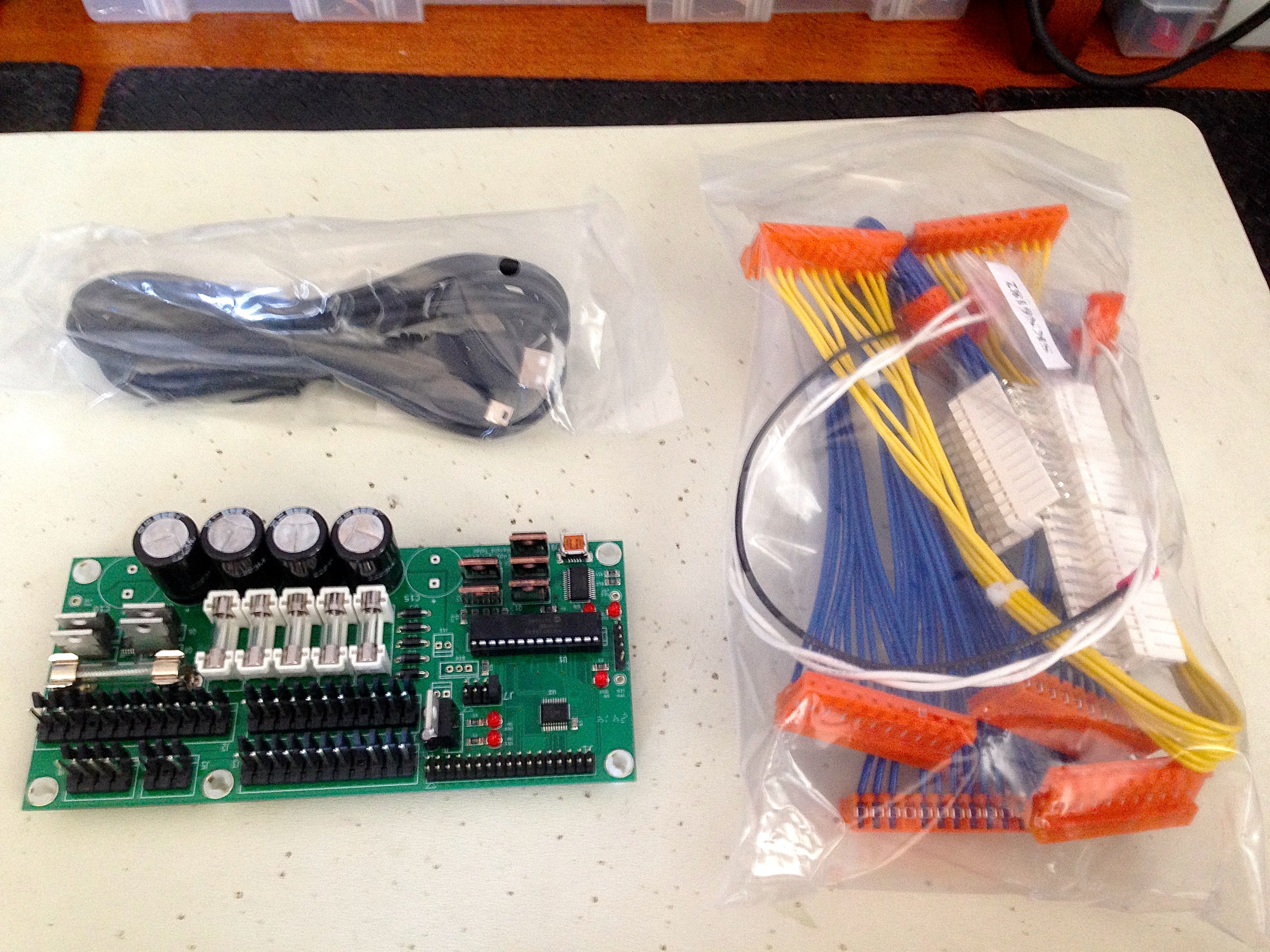
It’s quite a nice kit. All the cabling is professionally made, the board is nicely assembled, and the instructions are detailed. There are versions of the board for various different pinball platforms. This is the WPC89 kit, for all WPC89, WPC DCS, and WPC-S games. Williams had a number of variations of the WPC89 platform, but for the GI lighting, they are all compatible. Johnny is a WPC-S game, which means it’s the WPC89 platform with the addition of the DCS digital sound system ( \m/ ), and encryption for the ROM code. Yes, DRM is everywhere, even old pinball machines.
The first challenge for installing the board is finding a place to put it. The backbox of a ’90s pinball machine is a very crowded place. The instructions recommend mounting the board to the left side panel of the backbox, next to the CPU. The lengths of the provided cables also suggest that’s really where you should put it. Unfortunately, that location is not an option for me, because I relocated my battery box to that spot.
I really want to leave the battery box in that spot, because it needs to be close to the CPU board, and the batteries need to be easily accessible such that you can change them while the machine is on without getting electrocuted. If the machine is off while changing the batteries, you’ll lose the game settings and scores, so this was important to me. A different location was needed. The cables provided by the kit aren’t long enough to stray very far, however. The GI OCD board needs to be mounted in the general vicinity of the area between the CPU board and the Power Driver board.
After a lot of fooling around and experimenting, I realized that, conveniently, two of the mounting holes on the GI OCD board are the same distance apart as two of the mounting screws on the Power Driver board. That meant I could replace those mounting screws with standoffs, and float the new board over top. Huzzah!
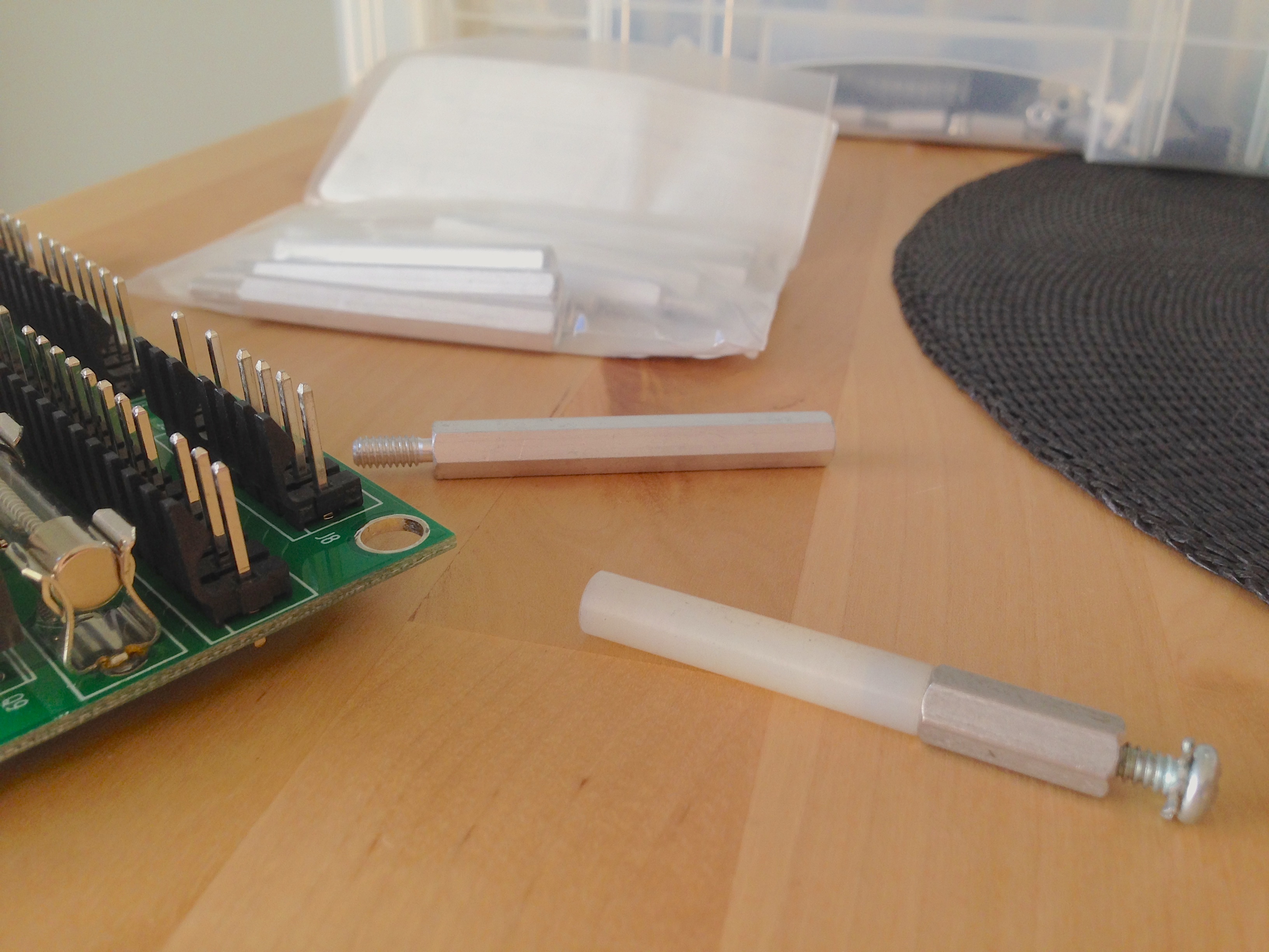
Getting the length of the standoffs just right is critical. There’s not much space above the main PCBs, because the lighting board for the back-glass and the dot-matrix display sit quite close. Furthermore, it has to clear the existing connections on the board, all the wiring, and the large heat sinks on the Power board. This last part is important. I can’t be sure how close-to-design-limit the heat sinks are, so I can’t know how critical air flow is. It’s best to err (pardon the pun) on the side of giving them as much breathing room as possible. So to speak.
Sadly, I didn’t have the exact height of standoffs I needed in the junk pile, so I had to place an order online. I hate it when that happens.
On the plus side, however, it gave me a chance to learn about machine screws. Since I was ordering something online, I needed make sure I was getting the right thing. The trick is, standoffs come in a lot of different thread sizes and types, and I wasn’t sure which I needed. Since I’m too cheap to buy a thread gauge, I needed to work it out the old fashioned way. Whatever I bought had to perfectly match the mounting screws for the PCBs so that they would thread into the same holes. With a caliper and a little math, we can work it out.
The hardware in these old American-built machines is of course Imperial, so we’ll be doing everything in that annoyingly-antiquated measuring system. Screws are generally specified with three numbers- thread length, thread diameter, and threads-per-inch. There are lots more measurements involved in making a screw (angle of the threads, pitch, depth, yada yada), but length, diameter, and TPI are enough to buy them. In this case, I needed 8-32 x 1/2″ threads. I’ll demonstrate how I arrived at this by examining a random screw from the junk pile.
First, the length. This is easy- measure the threaded portion of the screw with the caliper.
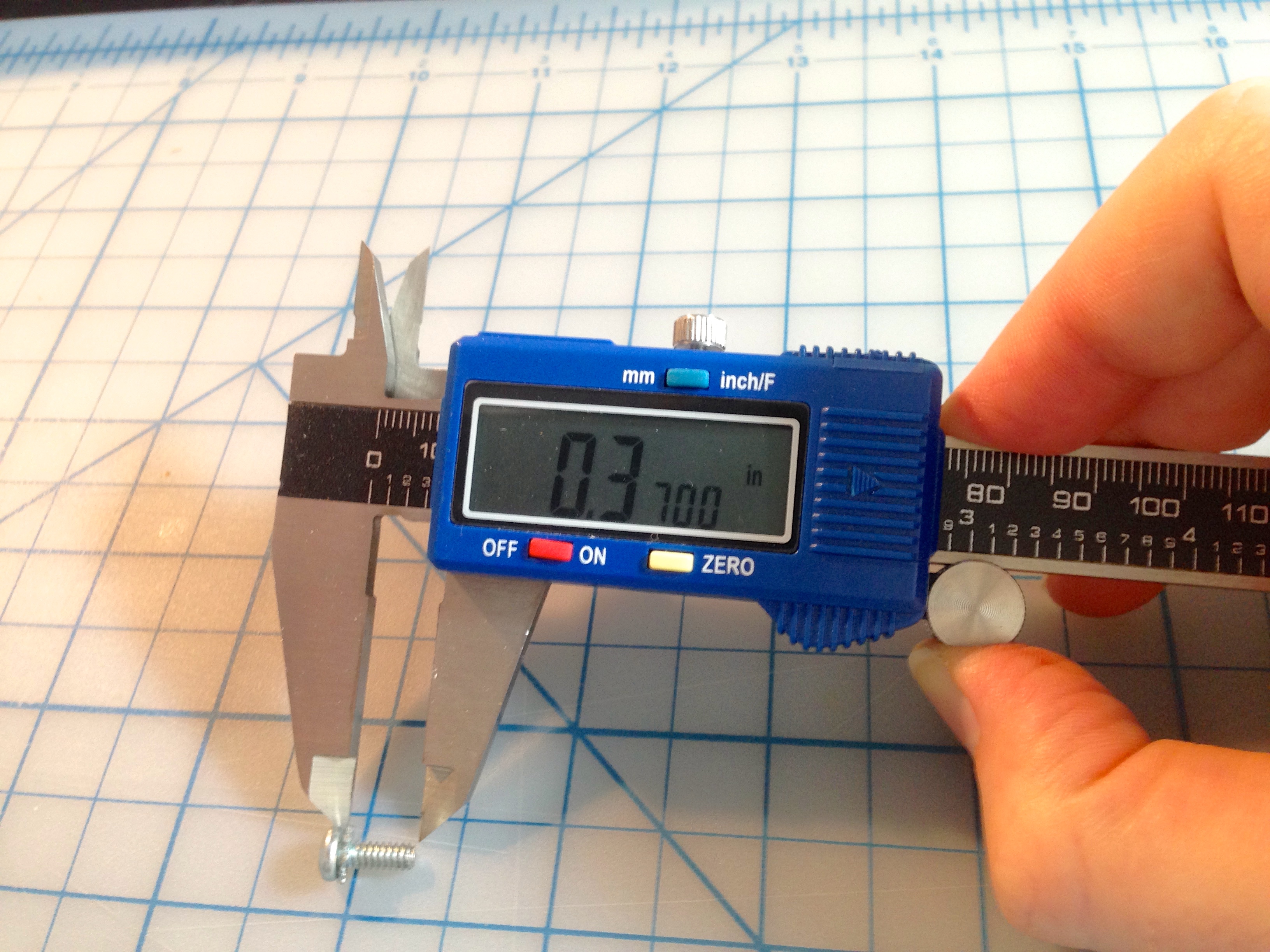
Next, diameter.
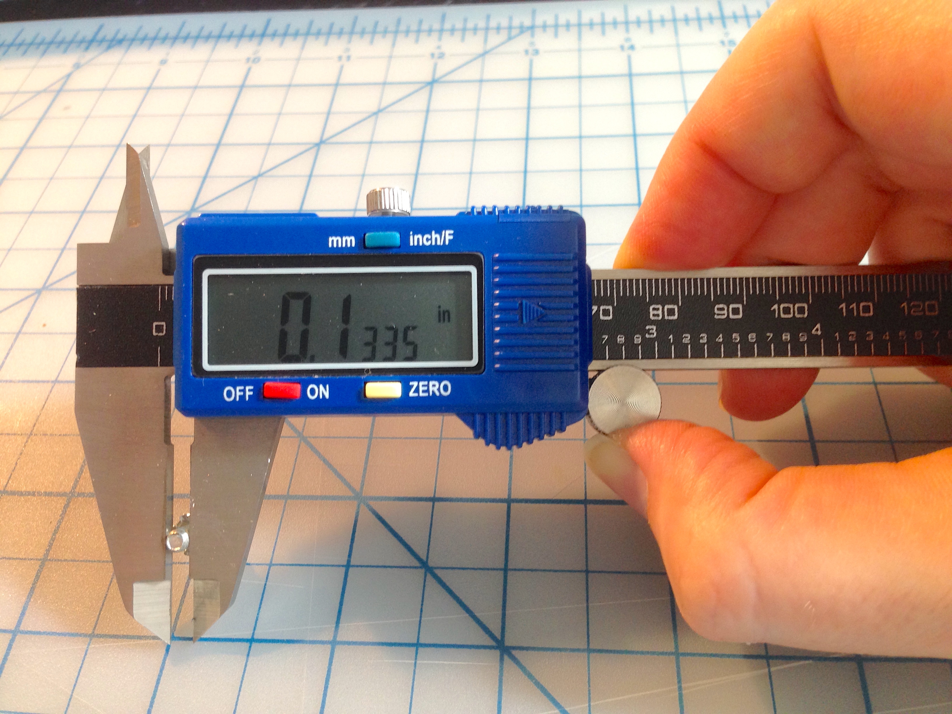
Screw thread diameters are generally given with a magic number, such as “4” or “6”. When I say the screw I needed was “8-32”, it’s the “8” that specifies the diameter. To map the above measurement to the magic number, use a machinists’ reference chart, such as this one. Our measurement of 0.1335 inches is very close to 0.138″, so this is almost certainly a #6 screw.
Lastly, we need the threads-per-inch. This is the trickiest dimension, but with a sharp eye, you can do it. The trick is to look at the edge of the threads, and count the peaks. Then divide that by the length we have to get the count for an inch.
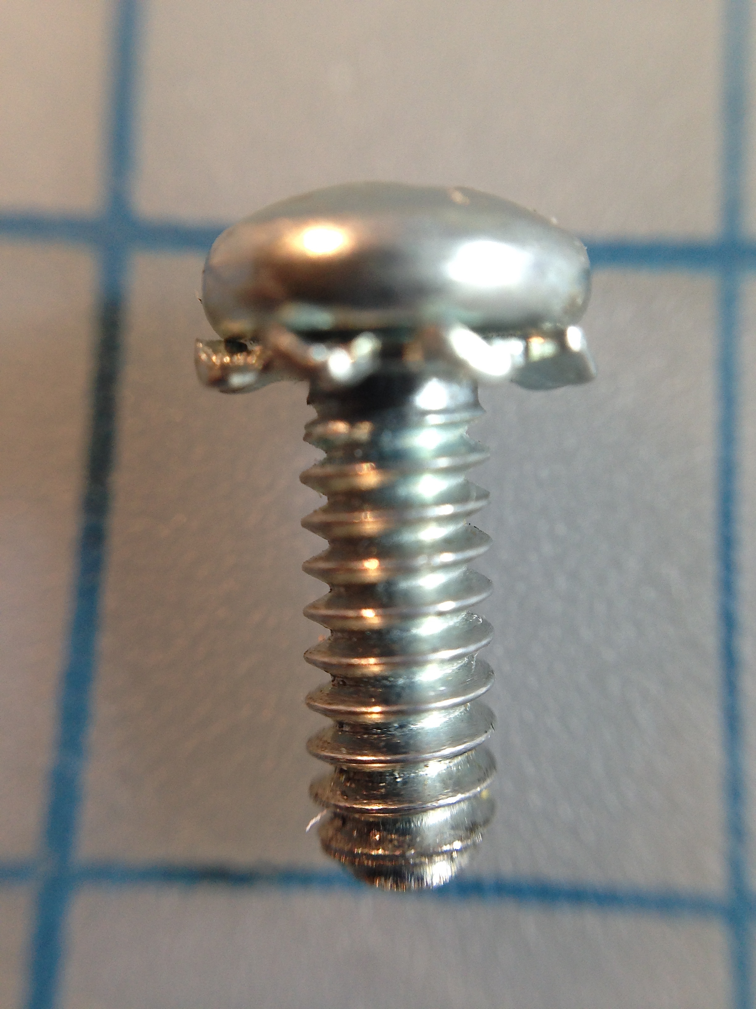
So for our sample screw, this calculation gives us:
12 peaks / 0.375 = 32 TPI
Consulting our machinists’ chart again, we see that this is a 6-32 x 3/8″ screw. Now we can order with confidence and know we’ll get something that threads in where we need it to!
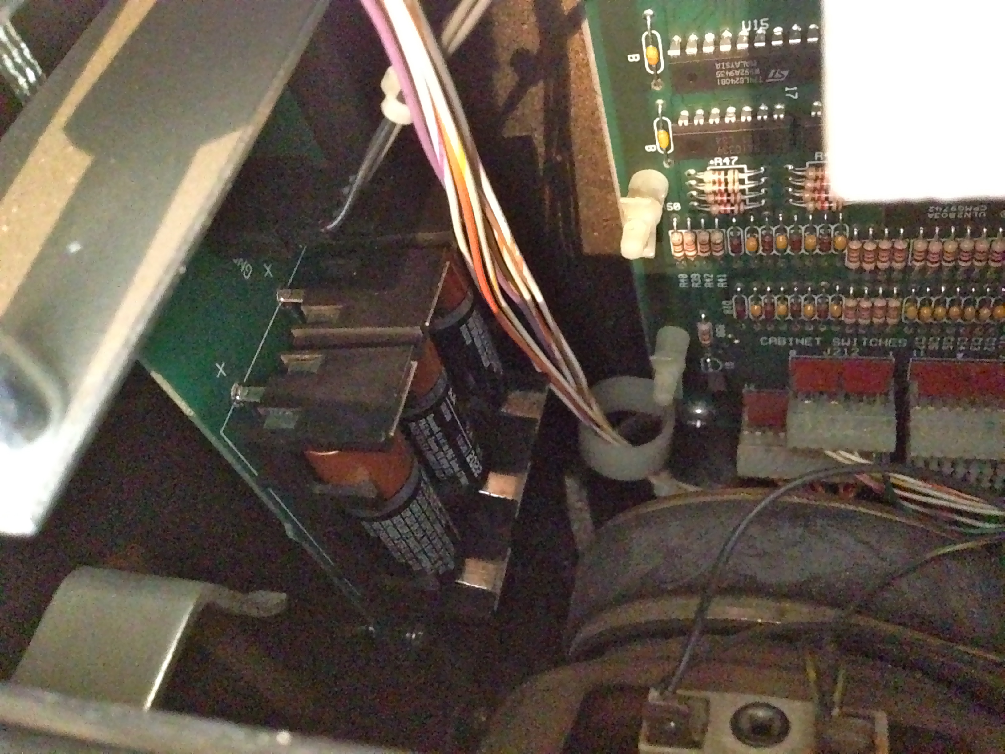
Now let’s get that shiny new board mounted.
Finding a way to mount the board is the only tricky part of the install. All of the cabling is handled by disconnecting things from the pinball machine’s normal PCBs, and splicing the GI board into them using these “Z-connectors”:
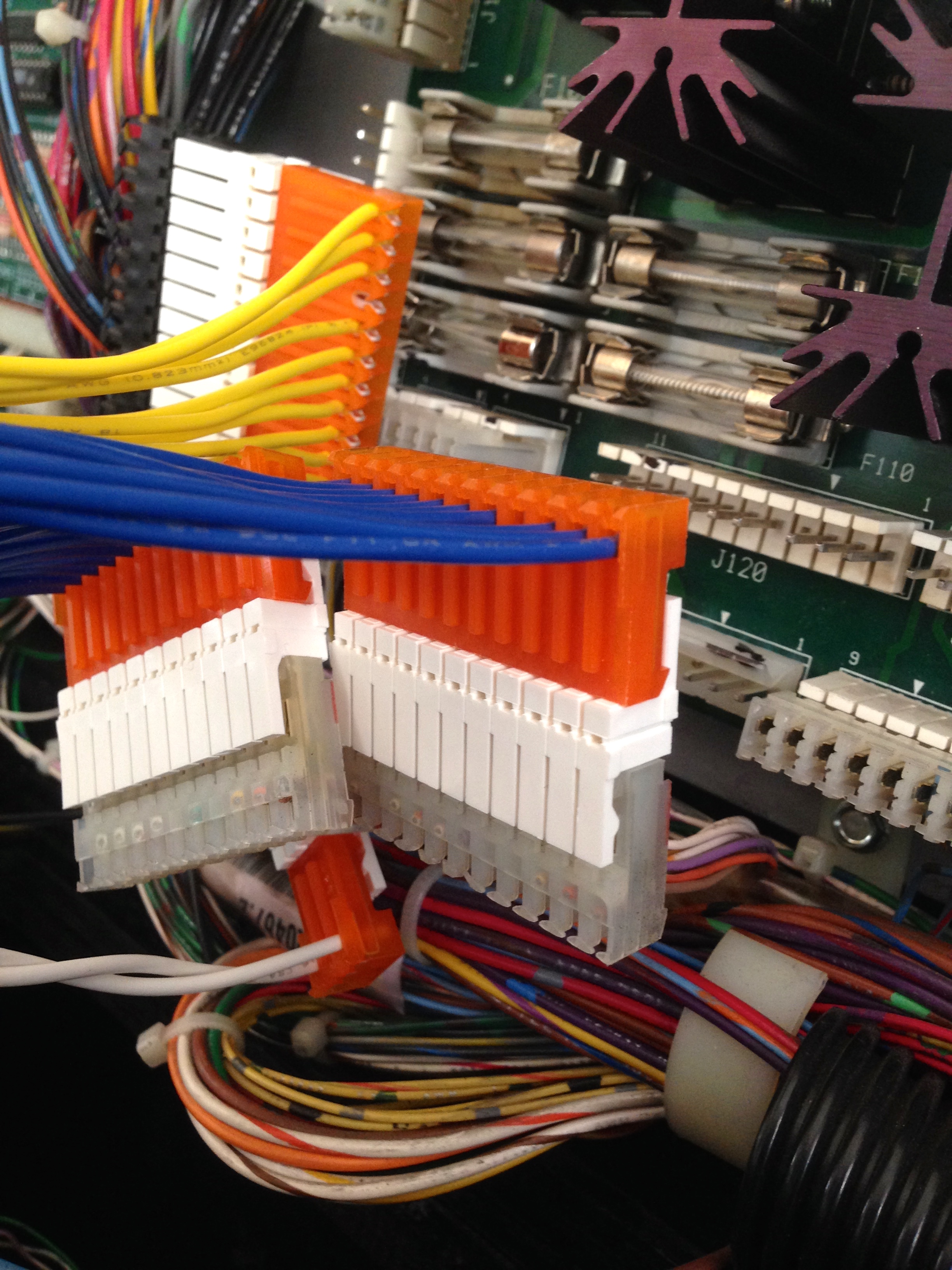
The nice thing about this approach is that the entire installation is easily reversible. We’re not cutting or soldering anything here. Some pinball people are sticklers for originality, so hasty modifications can hurt resale value. Furthermore, this GI OCD board is a bit of a luxury, so if Johnny needs to find a new home someday (perish the thought), I might want to keep this board to use elsewhere.
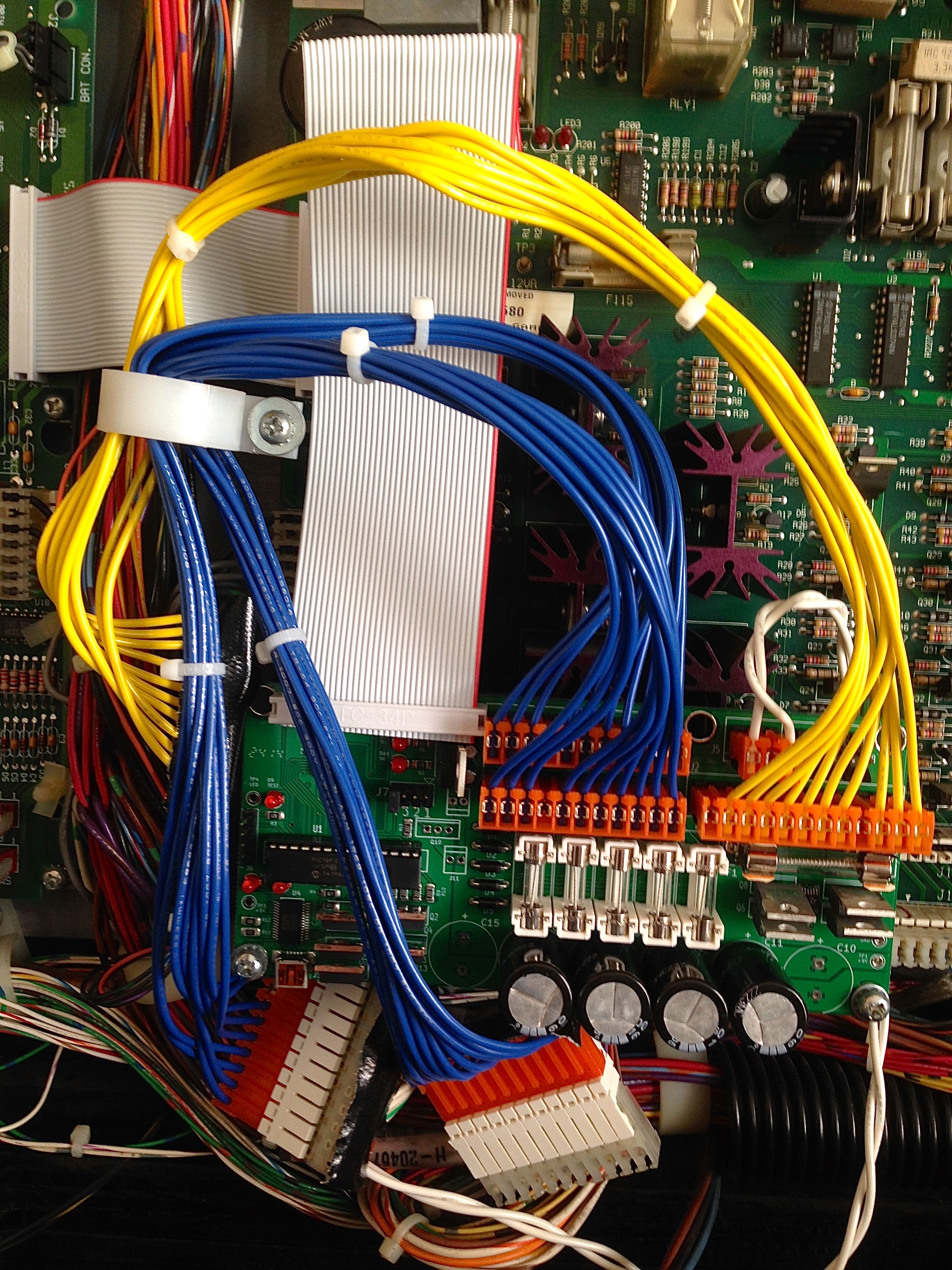
A few things to note from that photo:
- There are two mistakes here. Do you see them? More on that later.
- Note that only the bottom mounting holes on the GI OCD board are used. This “double-decker” installation is only possible for two holes. That seems fine, though. The board is plenty sturdy with just two mounting points.
- There’s about 3/4″ of clearance between the back of the board and the large heatsinks behind it. This seems like it should be sufficient.
- There are strips of Gorilla Tape on the backs of the connectors that were spliced into. Since they’re hanging at funny angles now, it’s important to make sure they don’t touch anything. The back of an IDC connector has exposed contacts.
- There’s an additional tall standoff mounted above and left of the GI board. I put that there so I could mount a cable clamp to secure all the cables.
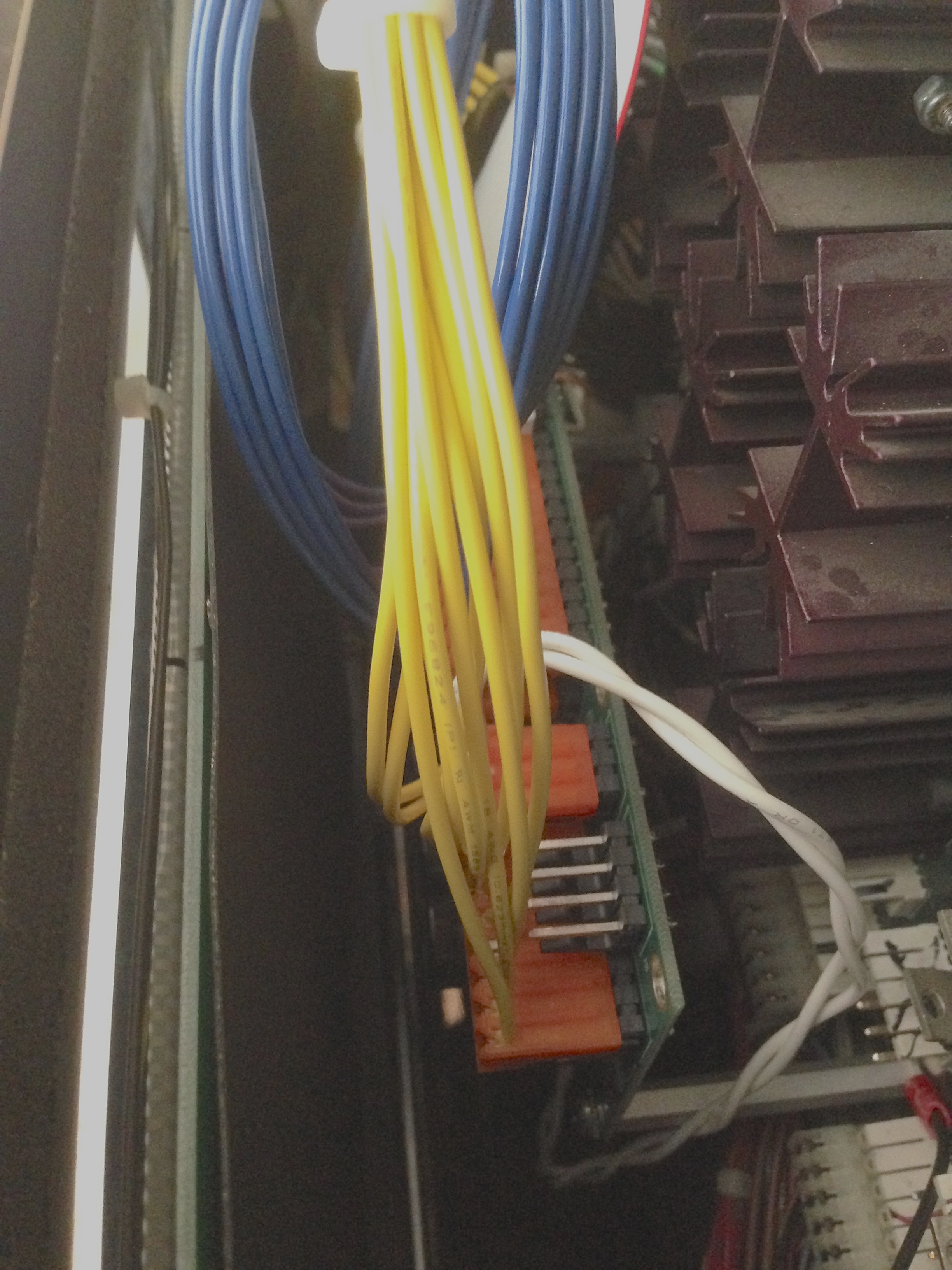
So, I mentioned two mistakes. What are they? Well, after connecting everything, it was time to power up the machine. Always a mildly tense moment with these beasts. On first power up, there was no lighting, and the cabinet knocker solenoid was firing over and over. Uh-oh. None of that is good. Seems like some connections must be wrong.
The cabling is all keyed, so the only thing that could wrong would be a missing connection. Guess what? I forgot to connect the ground cable on the GI OCD.
Second power up, we have lighting. Hooray! But, the knocker is still firing, and the game won’t boot. Rut-roh. At this point I decided to look at the online-version of the instructions. The paper version included with the kit has written instructions, but no pictures. The online version is much better. Remember how I said all the cables are keyed? Well, all except one. The big ribbon cable that connects the CPU board and the Power Driver board. All the data signals for various game systems run on this cable, and it isn’t keyed, other than a red stripe on the cable itself. The instructions for the kit have a big bold warning that says to make sure this cable is oriented correctly. I read this and, of course, thought, “Pfft- I’m an experienced hacker. I got this”. I then proceeded to install it backwards. Never underestimate your own stupidity.
Luckily, no harm done, and reversing the cable fixed it.
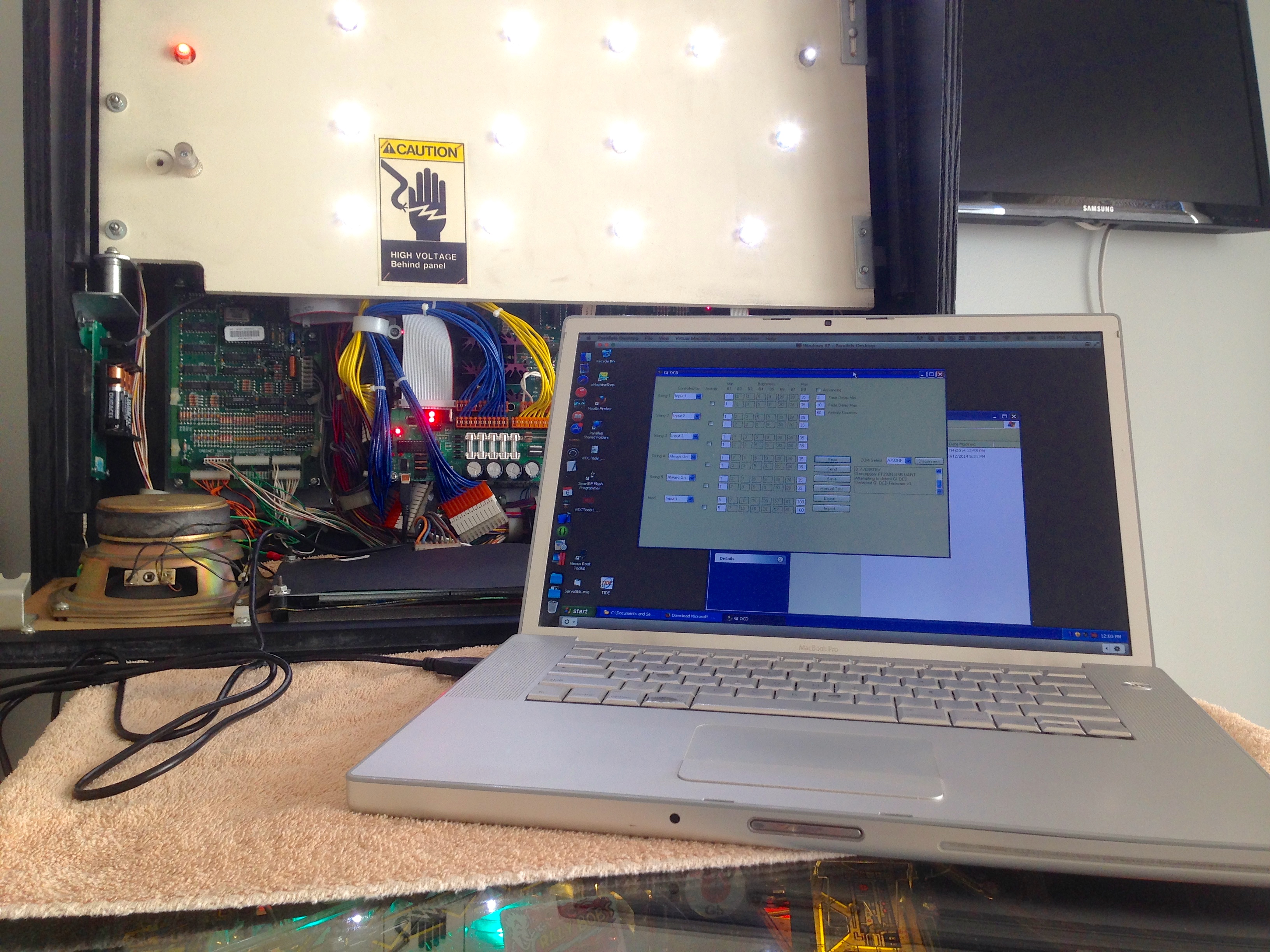
Third power up now, and everything works beautifully. The difference is dramatic and immediate. The dimming effects are something I’ve been living without for so long that I didn’t realize how much I was missing. It’s like a brand new game now!
Here’s the final installation with the dot-matrix panel reinstalled. It’s cozy in there, but it all fits.
Now, behold the awesome power of pulse width modulation.
But wait, we don’t have to stop there. For further evidence of how crazy pinball people are, every detail of this lighting system can be mind-numbingly configured. The board comes with software for programming the microcontroller that is doing the voltage-to-PWM translation. Sadly, this software is Windows-only; but that’s why we have virtual machines. Being Windows (and .NET) the installation process is fairly hostile to users. It took several tries and some tech support before I could get the software running, but here we are:
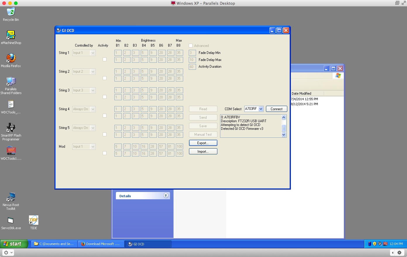
Frankly, I find the default configuration to be just peachy. However, it’s nice to know such obsessive levels of adjustment are possible. This could be a boon if, for example, you have different colored LEDs in your GI. Some people like to light up different parts of the playfield with different colors. The settings on this board would allow you to balance brightness to compensate for variations introduced by color. There’s a large thread over on the Pinside forum where people are sharing their settings for various games.
The end result looks so good that now I’m tempted by the companion product, the LED OCD board. This works similarly to the GI OCD, but it’s for gameplay lighting (the lights inside playfield markers and such). I don’t think the Blondihacks budget has any more room in it for pimping out Johnny, though. He’s going to have to get by on his brains for a while.
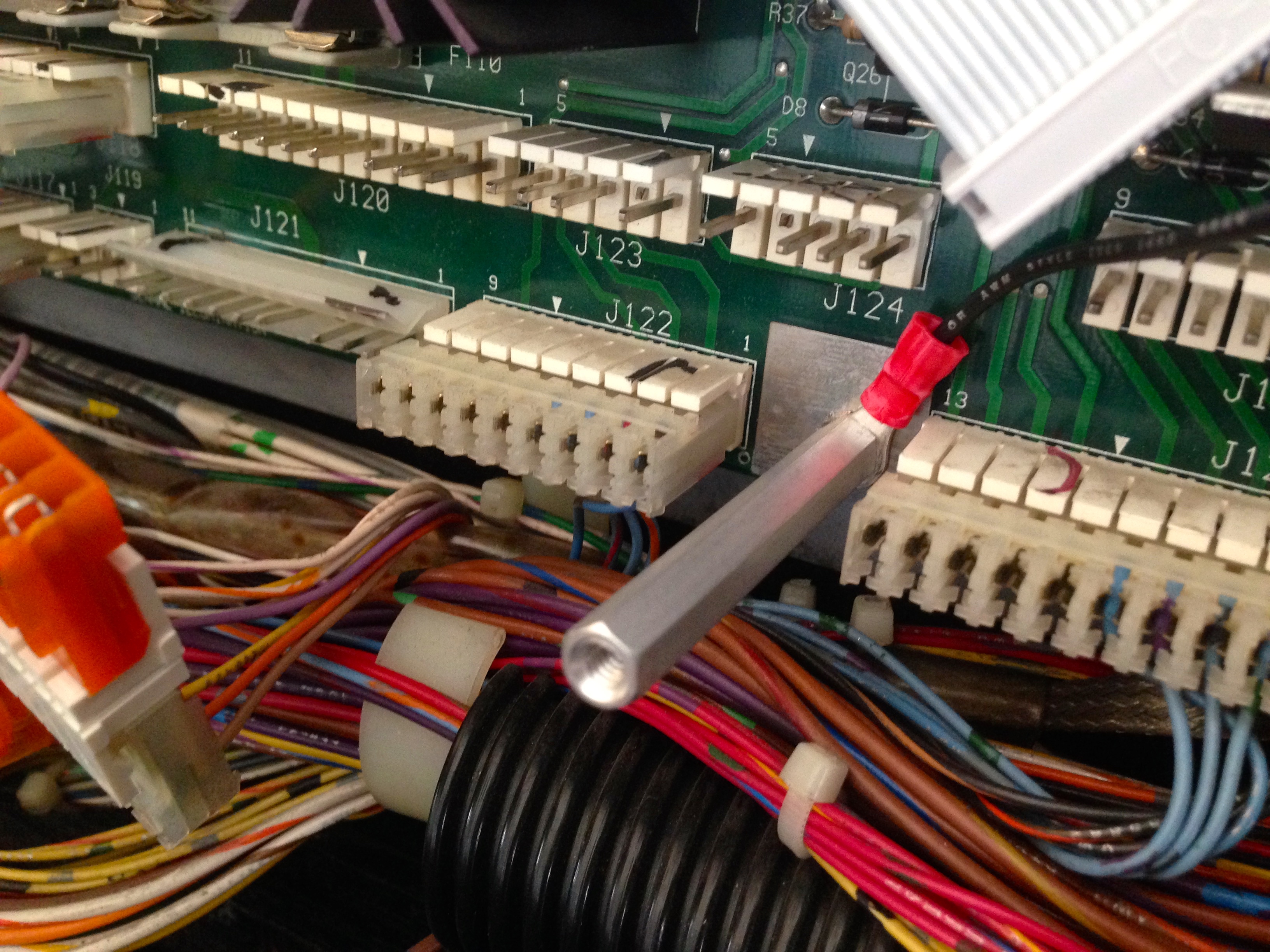
Odd question. The connectors in that machine (the white/translucent and sometimes orange ones that go from board to cable) — what are those? I’ve seen them exactly one other place ever and they intrigue me a little. They certainly don’t look modern!
Oh — and regarding the floppy controller chip from the other comment I made recently — it’s not new 😉 that chip has been around since at least the mid 80s IIRC. If you’re going solid state, though, you might take a look at the XT IDE project (what’s left of it, lol) and its various spinoffs. I’m building this version for my XT box, since the Seagate ST-238R can’t find its geometry any more (I don’t blame it, I turned two a couple weeks after it was built!) and I’ve no idea how to fix that –> http://www.lo-tech.co.uk/wiki/Lo-tech_ISA_CompactFlash_Adapter_revision_2
Those are called IDC connectors. They were/are popular with pinball manufacturers, because they are fairly robust and very fast to assemble in a factory setting. You can read more about the engineering, history and reasoning behind pinball connectors here:
http://blondihacks.com/?p=1737
Regarding the floppy controller chip, I only meant “new to me”. :o)
I thought IDC connectors were PATA HDD style connectors. Totally different creature, at least judging by appearance…
I’m confused now!
It’s possible the acronym is overloaded in other domains. I don’t know much about hard drive standards. In this context, it means Insulation Displacement Connector. It’s common in commercial equipment, telephone switch gear, and similar realms. It’s essentially a series of v-shaped knives that you push the wires on to. The V cuts the insulation and grabs the wire. There’s a special tool that feeds the wires and makes the connections sequentially with a single button push, like a semi-automatic pistol. That makes it popular in manufacturing.
http://en.wikipedia.org/wiki/Insulation-displacement_connector
Hard drive connector image –> http://en.wikipedia.org/wiki/Parallel_ATA#mediaviewer/File:PATA-cable.jpg
…well, for the kind I’m talking about (Parallel ATA, which is the older kind). I’m surprised you don’t know that stuff — especially considering you’ve almost completely built a computer. Admittedly Veronica is much older tech than that (MFM hard drives like my sadly deceased Seagate ST-238R would be far more her style) but knowing modern computer stuff is a good idea as well. Comes in handy for maintenance type stuff 😉