The tradeoff of time spent learning tools.
This article is ostensibly about a particular piece of software, and its relationship to 3D printing and machining. However, I think there’s a larger message regarding complex modern tools, and the economics of spending time to learn them.
For a long time, I was an avid user of 123D Design, the hobbyist 3D modeling tool from Autocad. Unlike traditional 3D modelers such as XSI, 3D Studio Max, or Maya, this was a tool aimed primarily at 3D printing and other hobbyist activities. The UI was very intuitive and straightforward to use. It suffered from performance and stability issues, however, and it had cumbersome workflows when you got into more complex models. You would spend a lot of time redoing things if you didn’t plan meticulously before putting mouse pointer to screen.
123D Design was recently retired, along with most of Autocad’s other side projects. They have rolled everything together into one monster software package, Fusion 360. Let me state up front that Fusion 360 is a really remarkable piece of software. It has been years since I was this impressed by an application. Even better, they offer it fully featured for free to hobbyists and students. The documentation is strong, the video tutorials are excellent, it is cross-platform, stable, well-supported, and extremely polished.
Make no mistake- this is serious software. In addition to modeling, it has rendering, animation, motion study, physical simulation, finite element analysis, engineering drawings, and more, all built in to one package. With all that power comes great responsibility comes a non-trivial learning curve. Software at this level is not something you should try and muddle through on your own. You’re likely to have a negative experience and give up. Time with the written tutorials and onboarding videos on Autocad’s site will be time well spent. But how much time?
Every tool like this has an efficiency calculus we must do- how much time spent learning it is worthwhile? Once we’re fluent with the tool, how much time will using it save us over other methods for getting our work done? Some tools become projects in themselves, and it’s easy to get sucked into the tool for the tool’s sake. For my money, if it doesn’t actually accelerate my process, I’m not interested. The strength of Fusion 360 is tricky to quantify, because what it’s really doing is eliminating errors you didn’t know you were going to make later in your project. A few hours in this tool up front may save you dozens of hours redoing work because you overestimated your own ability to keep a project in your head. That’s an abstract benefit, so let’s take a look at a case study of this effect to anchor it in reality.
As regular readers know, I’ve been interested in machining for some time now. After many fun projects with my lathe, power hacksaw and drill press, I was hungry for more. Like many people in this space, I’ve had a lifelong fascination with steam engines. I now (barely) had the tools to make one from scratch, and I dearly wanted to give it a try. I don’t (yet) have a milling machine, so I needed an engine that I could make with only a lathe and drill press. That’s a steep constraint. I wanted to start by building someone else’s design, so that I’m not trying to learn precision scale machining and steam engine design at the same time. Both are lifelong learning topics in their own right. After much searching, I stumbled on to the perfect beginner project- Steve’s Workshop’s take on the classic wobbler. I can’t thank Steve enough for this brilliant design. It’s easy for a beginner to make, requires only a lathe, and it’s very forgiving to operate. The only real catch was that the plans were all in metric, and I needed to work in Imperial units. More on that problem in a moment.
It may seem like I’m burying the lede here, because documenting the making of a steam engine is exactly the sort thing for which this blog exists. However, because I had so much on my plate with this project, I opted not to document it to the level required for a Blondihacks post. As any internet content producer knows, doing a project “for the camera” is 2-3 times as much as work as doing it alone. Not to worry, it won’t be the last steam engine I make, so you’ll see a project like that here at some point. Instead, this first project serves as a good case study for the value of planning, and learning your tools to make that planning more efficient.
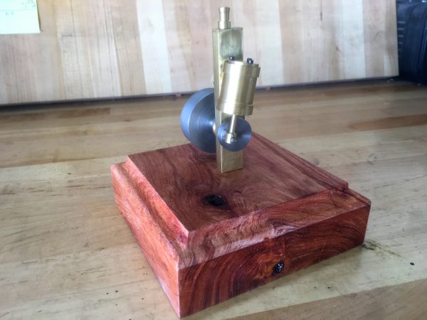
Here’s video of the first successful test run of this engine. It was a glorious, glorious moment. The culmination of dozens of hours of sweat, frustration, failure, and occasionally doing things right.
After some tuning, it ran even better.
For those interested, a quick sidebar on this type of engine is in order. This is colloquially known as a “wobbler”, though officially it’s referred to as an “oscillating cylinder” engine. It is in the category of “cylinder ported” engines, which also includes the really unusual elbow engine. Steam engine design is a deep and broad topic- remember that humans spent three hundred years refining this technology before gasoline came along. Invented in 1841, the wobbler was initially popular as a marine engine because it has few moving parts, is easy to repair, and has a good power-to-volume ratio. Space is precious in a boat hull!
Anyway, the beauty of the wobbler it is that it requires no separate valve gear. The piston rod is a single linkage relative to the crankshaft, and the cylinder is mounted on a central rotating trunnion. This geometry forces the cylinder to wobble back and forth in a fixed and predictable arc as the piston rotates the crank. The valving for steam intake and exhaust is handled by the oscillation of the cylinder, causing a single steam port in the cylinder to alternately align with intake and exhaust ports located in the stationary chassis. It has very few moving parts, which makes it a great learning engine. It’s obscenely clever, but far from an ideal design. The limitations include:
- Rotating the mass of the cylinder saps power, and limits the ability of this engine to scale.
- The mating surface of the cylinder to the chassis is being asked to do a lot, and at best forms a leaky seal with high friction and plenty of steam losses.
- The intake and exhaust ports are limited in configuration by the arc described by the motion of top of the cylinder. This means the power stroke can’t begin just past top dead center, as you might want. Rather, it must begin halfway up. Similarly, the exhaust port gets closed halfway through the exhaust stroke, causing loss of efficiency as the piston must force waste steam out past sealing surfaces (such as the piston rings or trunnion area).
- The engine cannot be reversed without swapping the valves.
- Automatic lubrication is difficult to achieve, because the cylinder face a complex motion and exposed bearing surfaces. Lubrication tends to be manually applied, which limits running time and speed. It also means the machine is a bit leaky and messy. Some consider that a feature rather than a bug in a steam engine.
- Ultimate operating pressure (and thus horsepower) is limited, because the cylinder’s sealing face must be loose enough to rotate, but tight enough to contain steam pressure. That’s a delicate balance that breaks down easily.
Despite all that, the wobblers are a forgiving design that wants to run. They are robust, run on compressed air or steam (even when poorly made, as we’ll see), and are compact for the amount of power they generate.
End of story, right? Girl meets machine tools, girl makes steam engine, steam engine pleases girl. It’s the oldest story in the book. Well, the thing is, my engine barely runs, it took me twice as long as it should have to build, and many parts of the process were frustrating. Instead, if I had sat down with a tool like Fusion 360 beforehand and spent a couple of hours making a plan, I could have prevented all that inefficiency. Fusion 360 stands out here by being in a rare category of tools that are both exceptionally powerful and exceptionally easy to use. Compared to similar-caliber tools like SolidWorks or Eagle, Fusion 360’s learning curve is amazingly gentle. Compared with other easy-to-learn tools like Sketchup, Fusion is vastly more powerful.
To emphasize this point, after spending about 30 minutes with Fusion’s excellent tutorial videos, I was able to knock out this motion study of a similar steam engine in about an hour.
Remember, that’s 90 minutes from installation to working piston linkage motion study, never having seen or touched this software before. That’s powerful stuff.
How would all this have helped me? Well, remember that I mentioned the original wobbler design from Steve’s Workshop was in metric units. Compounding the confusion, the threads and fasteners were on the British Association standard. I needed convert all that to Imperial units and ANSI threads. I naïvely thought that I could simply convert as I went along, referring to Steve’s drawings to build the engine. However, because metric and imperial units never line up to nice round numbers, you generally end up rounding a bit one way or the other. When you round things, you are making part of the model larger or smaller. If the rounding is done in different directions or different amounts (which is likely) on different components, you are changing the relationships between all the parts of the engine. To make matters worse, standard elements like tool steel drill rod (called “silver steel” in the UK) comes in different standard sizes in different countries, so parts of the model must be adjusted for that as well. All these problems also apply to screw threads and fasteners.
It would have made sense to sit down with the drawings and convert everything at once, instead of trying to keep it all in my head. That’s one lesson learned. Converting the measurements is tricky though, because as I said, the relationships change when you do that. I might end up with an engine that looks great on paper but doesn’t actually run any more. This is very nearly what happened to me, and nobody wants to spend dozens of hours in the shop building something that doesn’t chooch.
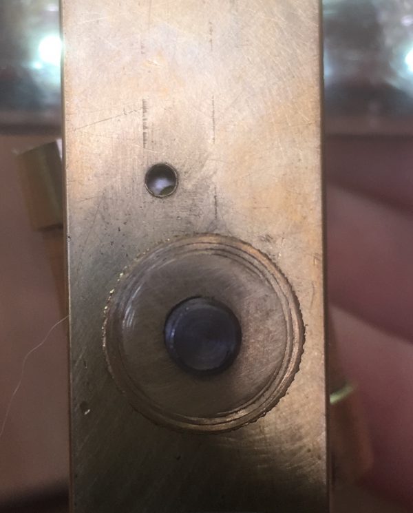
As you can see, the valves on my engine ended up being poorly aligned because of all the rounding and conversion. Fortunately, this engine design is forgiving enough that it runs anyway. It loses of lot of efficiency though, and puts a lot more demand on the sealing surface of the valve face. This is because higher steam pressures are required to get decent power, and the limiting factor in our operating pressure is that cylinder-face seal. This kind of subtle valve misalignment is very difficult to catch in a drawing- even a carefully converted one. There are a couple of approaches to preventing this problem:
- Old school. Rather than trying to calculate the valve positions, just build the engine without the steam ports and then transfer-punch them from the cylinder’s actual movement. For a one-off, this works great. It guarantees alignment for one specific engine.
- New school. Model the engine ahead of time in a tool like Fusion 360, and use the motion study tools to ensure alignment and proper operation of all parts.
Option 2 is very powerful indeed, but may only be worthwhile if the tool is easy enough to use. If it requires weeks of learning curve to master the tool sufficiently to model a simple engine, you’re better off just winging it and using some fabrication tricks (like transfer-punching positionally related elements). We’ve arrived at why I want to talk about Fusion 360 in this context. The learning curve is so gentle and the tools so intuitive that you can get to Option 2 very quickly. This unlocks a lot of doors for gains in efficiency, and the complexities of projects you can tackle. For example, I can design more sophisticated engines without having a very good grasp of the math of steam engine design, because I can work things out empirically in the tool. Similarly, I can “design” engines based on principles of other real ones seen in operation, just by mocking them up virtually and generating plans from there. Fun!
Give all that, let’s “redo” the process of building the wobbler, using Fusion 360 in our workflow from the beginning.
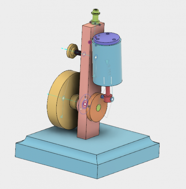
I started by modeling the engine using Steve’s Workshop’s plans as a guideline.
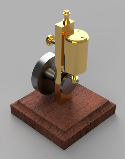
Then, just for fun, I added materials and rendered it.
To get the critical steam port alignment, I created joint constraints between the relevant components such that it moved as intended.
I could then simply position the piston at the start of the power stroke, and Fusion would determine where the crankshaft and cylinder will be at that point. A couple of boolean operations on the geometry then cuts the intake valve at the correct position. The same thing is done for the exhaust side.
Next, using Fusion’s powerful engineering drawing tools, it was a simple matter to generate a set of drawings for the model. For example, here’s the aforementioned frame, with the tricky-to-place steam ports.
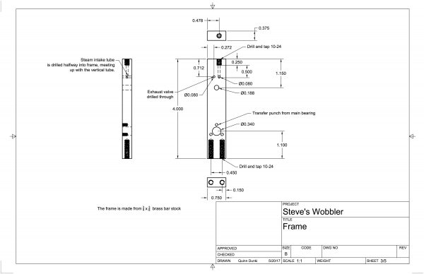
Here is the complete set of drawings (PDF), for those who are interested in making this engine.
There’s one more key way that Fusion helps iterate and save time on designs. The entire pipeline is parametric. What that means is that the 3D geometry is created from “sketches” you create in 3D space. That geometry is then used in operations to create other geometry. The combined geometry is then used to generate the engineering drawings. All of those associations remain intact and alive- everything is derived from something earlier in the process. You can go back in time to any point, make a change, and everything after that reflects the change. If you look at my drawings, you’ll see I planned to use 1/4″ O1 tool steel drill rod for the crankshaft. This is a strong and very precisely dimensioned material with a beautiful finish that makes excellent spinning shafts. Now let’s say that when I go to build the model, I only have 3/16″ drill rod on hand. That will be good enough, but now my drawings are all wrong and we’re back to the on-the-fly conversion and scaling problems that I talked about earlier. With Fusion, however, I simply go back to the sketch that defined the diameter of the crankshaft, and change it. The entire design propagates that change. The interior diameter of the bronze crankshaft bearing changes size, the mounting arbor on the flywheel adjusts to match, the various set screws move inward as needed, etc. Even the final engineering drawings all the way at the other end of the pipeline are completely updated with one click, and I can now make this engine with a 3/16″ crankshaft. That’s one small example of the power of a parametric approach to complex machine design. This is in stark contrast to more direct modeling tools where all you’re doing is manipulating 3D geometry directly. Once you’ve experienced parametric construction like this, you will never want to things any other way. I would never claim that every tool is worth your time, but with something like Fusion 360, I think the (frankly modest) learning curve is worthwhile. This tool is a force multiplier in a way that few pieces of software are.
All that said, Fusion is not full time chocolate rainbow puppies. My main issue with it is that the file management is cloud-only. I guess I’m old fashioned, but I like to have all my hard work saved locally in a file that I can back up how I want, and won’t go away because some company decides to take their server down. The cloud file management is all part of their workgroup solution for collaborating on designs, so I sorta get why they did it. However, I’d prefer that an application use text-based file formats that can be merged, and let me use git or Perforce or whatever I want for collaboration. Also, while performance is generally very good, the engineering drawing section is rather sluggish. It seems to struggle with refreshing and input responses are often delayed. Perhaps being at the end of the parametric pipeline, this module is doing a lot of processing. It’s counterintuitive, since the actual rendered output is by far the simplest.
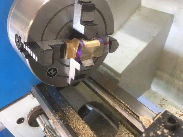
Okay, back to our little case study engine. Steve’s Workshop has a good set of instructions for making this, but I have a couple of suggestions to add. The key component of this engine is the flattened side of the cylinder. A reciprocating engine by definition needs valves, and that means you have to have two mating surfaces. That generally (but no necessarily) means flat surfaces. That makes the “lathe only” constraint for construction a bit tricky. Steve suggests using a milling attachment on a lathe for this, but that’s an expensive option that is not available on all lathe models. Instead, here’s a simple way to do it with the four-jaw chuck.
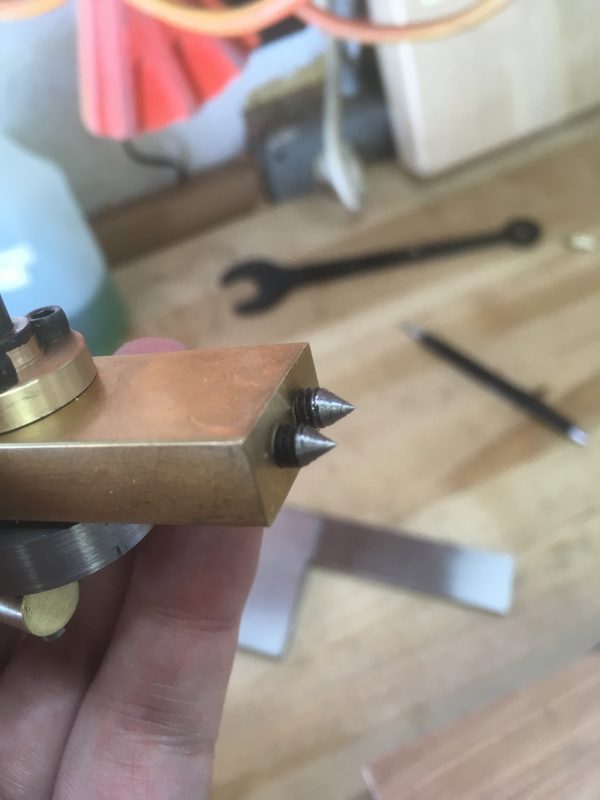
If, like me, you want to use a wood base (rather than the metal one suggested by Steve), then getting the mounting holes precisely aligned can be problematic. Wood isn’t amenable to the dye-and-surface-plate layout techniques we’d use to do this on metal. To solve this, I went old school and made some little transfer punches. I cut the heads off some bolts of the appropriate size and turned a point on them using the lathe.
Also, while not completely required, I recommend sanding one side of the frame flat with sandpaper (increasing grit in stages from 240 to, say, 2000). Place the sandpaper face up on a very flat surface such as a surface plate or pane of glass. This will get the side of the frame to mate better with the cylinder, without needing to mill anything.
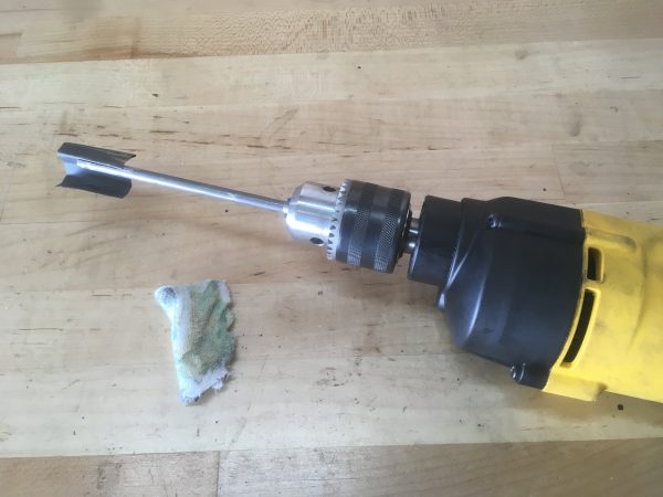
To hone the cylinder, I made a mandrel with a slot cut in it to hold sandpaper. This is chucked into a hand drill and spun at high speed inside the cylinder. The grit can be gradually reduced from 800 down to 3000 to get the best possible smooth sliding fit for the piston. Honestly, I’m not convinced this step is strictly necessary for a running engine. It’s another source of efficiency loss, but with a model running on air, we can always turn up the pressure a little more.
That’s it for this little project. I hope you’ll take a shot at both Fusion 360, and at making a steam engine like this. It is by far the most satisfying thing I’ve made in the shop, and it won’t be the last such contraption to make an appearance on these pages. Fusion 360 will help ensure the next one goes very smoothly indeed.
been looking for something to replace my aging copy of 3d studio max for some time now. been using it for modeling for years. i started using it for game models when i was still doing mods, but have transitioned to using it for my 3d prints. not wanting to throw out my modeling workflow a cad product proper would likely cause. after all the only difference between modeling for a print and game models is textures and the oft dreaded uv mapping. less work is good.
but i might consider using this if i can get over the notion that cloud computing is somewhat evil.
I had better luck getting good 3D print-able models out of a tool like this, because it seems to be better at generating geometry that doesn’t confound slicers. I was never an expert in Max or Maya though, so perhaps it was user error. 🙂 For things that are going to be physical objects, I think the Autocad style of modeling (focusing on extrusions and booleans, rather than vertex and face manipulation) is better suited to getting something that looks and feels right.
Anyways, I share your discomfort with cloud-based anything. Part of me is convinced it will be the death of us all somehow. At the very least, it will be the cause of me losing a bunch of data that I’m really fond of.
max does have some pretty good boolean tools. sometimes i even use them when im not being anal about my models. but then you can go over the resulting geometry and fix any resulting errors at the mesh level. its not very good at examining the interactions of moving parts though.
with 3d printing now less is more so i can go nuts with non complex geometry. when you are used to working with models in the 10k poly range, dropping down to 500 or so is really nifty. the how is a little different, you are always checking slopes and wall thickness to make sure its actually printable and so long as you have a large flat surface on the build plate anything goes.
I’ve been having a debate with myself over whether I should devote time to learning Fusion 360 instead of creating 3D models with OpenSCAD. Modeling in OpenSCAD is essentially writing code, which I’ve been doing for decades. Fusion 360 is obviously *not* about writing code, so it’s outside my comfort zone. I realize that learning Fusion 360 would provide me with a richer tool, but without knowing concretely how much richer it’s hard to motivate myself. Thanks for giving me a very concrete example of something that Fusion 360 does very well.
Being a software engineer by trade myself, I am quite fond of OpenSCAD as well. I’ve used it to make many 3D printing projects. For projects of a high complexity level, however, I really appreciate delegating all the complex relationships to software like this. I think as a programmer you will appreciate the parametric approach to modeling and design. It’s very elegant and intuitive for software people.
One problem with OpenSCAD (for those of us who prefer to work in thous) is that it really really wants to work in metric. It claims to be agnostic wrt measurement system, but things like the threading library want the units to be in millimeters. See http://dkprojects.net/openscad-threads/, where english threads are specified in imperial units, but the result uses millimeters. You could probably hack it together by doing conversions all over the place, but that way lies error and the various problems Quinn outlined above.
I did a workshop with Fusion 360 at the Hackaday Conference in Pasadena last year. It looked like it was designed as a much longer workshop that they had to cut short to fit into the time limit; that was a bit unfortunate because we barely got an idea of what it could do. We did end up with a 3D milled Fusion 360 logo keychain in wax, which looks pretty cool 🙂
However: I’m not very interested in 3D design (yet?) and the Software-As-A-Service model is a show stopper for me. If I buy a license to a program, I want to be able to use it anytime, forever. And if I remember correctly, though the features were very impressive, it wasn’t cheap to rent it either. Anyway, it made me go: “Meh, maybe some other time I’ll look into this”.
===Jac
Well, for hobbyists and students, Fusion is free. The file management is cloud based, but the application is fully resident on your machine and you can use it offline. I wouldn’t call it a service model in the way that you mean. My guess is that someday someone is going to make a hack to bring the files back to local, or users will protest sufficiently to make that an option. I would gladly give up the collaboration and version management part of the package in order to get local file storage.
Is this the file saving you’re looking for?
https://knowledge.autodesk.com/support/fusion-360/troubleshooting/caas/sfdcarticles/sfdcarticles/How-to-make-a-local-archive-back-up-file-in-Fusion-360.html
Hey thanks for the info Nathan! That’s very helpful. Certainly better than nothing, though it would still be nice to have an option to save locally as you go along. A periodic export to local file is a big help though, thanks!
Maybe you can send an export command periodically through the API? https://autodeskfusion360.github.io
That’s a nifty idea, and certainly worth a try. Nice to know the API exists. Sure would be nice to have a simple “Save As” in the File menu though. 😉