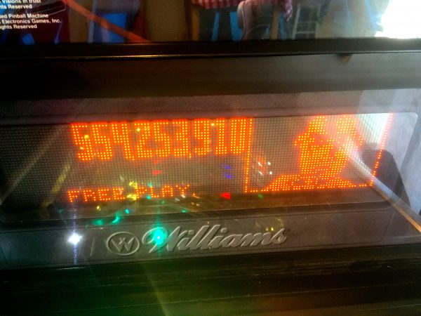
A glove, a drop target, and a matrix, oh my!
Pinball machines operate in a special realm where the normal laws of physics don’t apply. In this realm, complex machinery is working perfectly for a long time, and then three unrelated systems all fail simultaneously. The odds of that are astronomical in the normal world, but in pinball world, it’s par for the course. Race cars also occupy this rarified physics bubble, but that’s a story for another time.
Of course, what’s actually happening is that multiple systems are starting to experience occasional glitches, and our human brains write them off in the moment. Eventually these glitches accumulate sufficient frequency that we decide Now There’s a Problem™. In something as complex as a pinball machine, the perceived odds of this happening to multiple things at once is really down to confirmation bias, selective memory, and our powers of apathy towards fixing things.
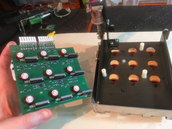
Johnny has been overdue for some love, and he was starting to pile up a lot of little problems that I’ve been ignoring for a while. First of all, one of the nine positions in the Cyber Matrix toy was occasionally not detecting balls. Meanwhile, I was playing my favorite mode (NAS Cure), and the drop target (which acts as a gate to control access to the glove) started behaving very strangely. It was consistently in the wrong position- it was preventing access to the glove, when using the glove is the whole point of this mode. Furthermore, it was popping up and down somewhat randomly in other modes. It was acting as though the CPU didn’t know what position the target was in. Then, while investigating that problem, the glove started throwing error messages about “No Y Progress”. This is a pretty common glove error- more on that in a minute.
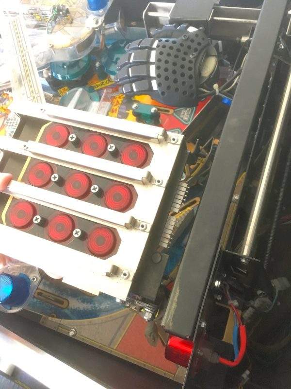
The point of all this was that it was clearly time to do a bulk repair of some issues. Let’s start with the Cyber Matrix switch, since that’s probably a simple problem (which I turn out to be quite wrong about).
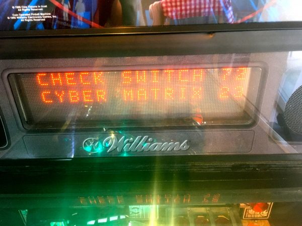
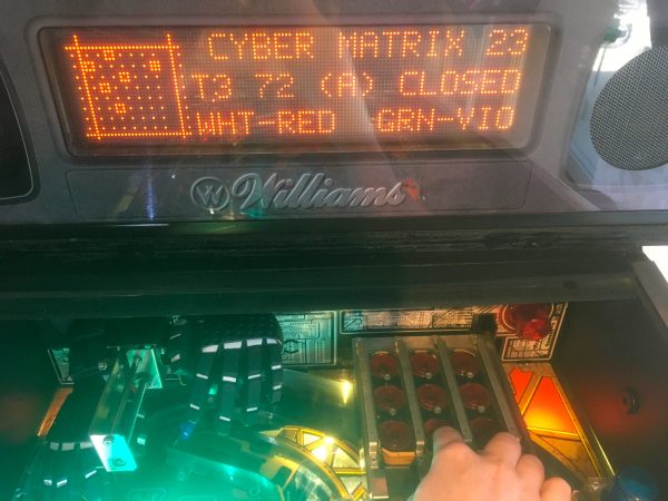
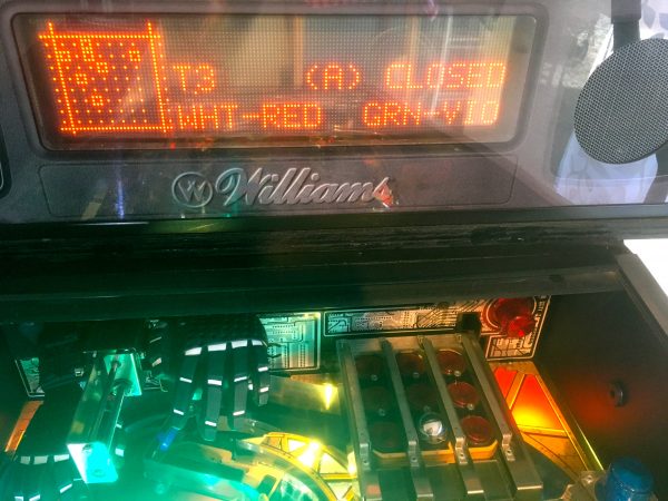
The way pinball machines detect failing switches is actually really clever. The switches tell the CPU where the ball is on the playfield. By definition, if the ball is supposed to hit a switch and doesn’t, the CPU doesn’t know where the ball is, and thus can’t know the switch in question failed to register. It can’t distinguish “ball not there” from “ball there but switch is bad”. The way around this is that the CPU makes the reasonable assumption that every switch in the game is going to get hit fairly regularly. How regularly depends on where it is. Ramp switches get hit a lot, whereas obscure parts of lesser-used toys may get hit very rarely. The game keeps track of how many rounds have been played since each switch was hit. Each switch has a threshold for the worst case of how often it should be hit. If a ramp switch isn’t hit, say, after five rounds, it’s probably not registering. A Cyber Matrix switch like this might not register for 30 or 40 rounds before becoming suspect. In this case, the Cyber Matrix switch has gone many many rounds without being registered, so the CPU flags it as “probably bad”. It’s a very clever statistical solution to an information gap problem.
Other systems report errors in different ways. For the glove, it was throwing the “No Y Progress” error, which means the computer thinks it is moving the glove forward or back, but the sensors say the glove isn’t getting anywhere. There are many possible causes for this, which we’ll get to. In the case of the drop target, there was no error code at all. The only symptom was erratic behavior during play. The computer helps us find problems, but it’s not perfect. Okay, time to put Johnny under the knife. We have three systems we’re going to pull- the Cyber Matrix, the drop target, and the Y-control board for the glove.
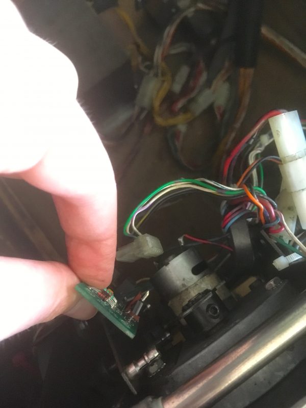
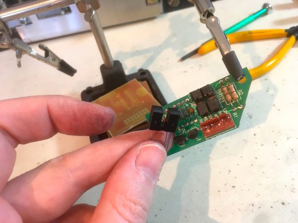
The detector boards for the glove have an optosensor on them, and the threaded rods which move the glove have a butterfly-shaped wheel on their ends. These wheels spin inside the optosensors, alternately making and breaking the infrared light. This creates a pulse train that the CPU can use to count the rotations of the shaft. Since the pitch of the thread on that rod is constant, counting rotations tells the machine how far the glove has moved (and whether it’s moving at all).
If you strip out a hole in the wood, there are some repair options. You can fill the hole with a piece of wood toothpick and wood filler (or bondo), then redrill a pilot hole. You can also install a metal threaded insert and replace the lag screw with a machine screw. When doing any such repairs, be incredibly careful not to drill or screw through the playfield, thus destroying the artwork and play surface above. At worst that can ruin the entire machine, or at best leave you with a very difficult and expensive repair.
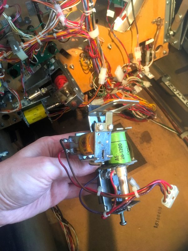

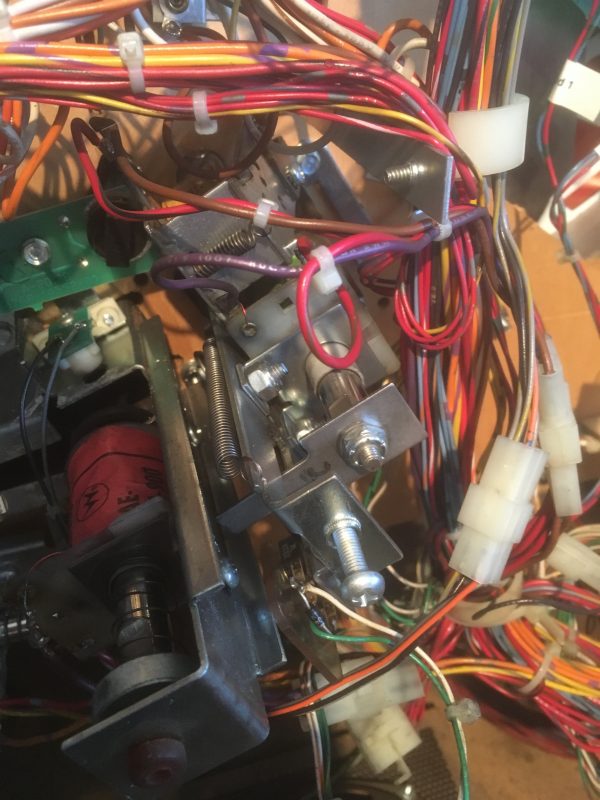
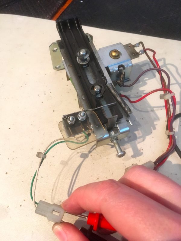
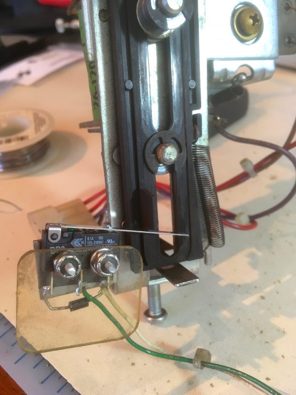
Let’s start with the drop target, since it’s a very interesting assembly. Drop targets are emblematic of what makes pinball machines so magical. It’s a physical thing that pops up and down, yet can be fully controlled both by ball impacts and software.
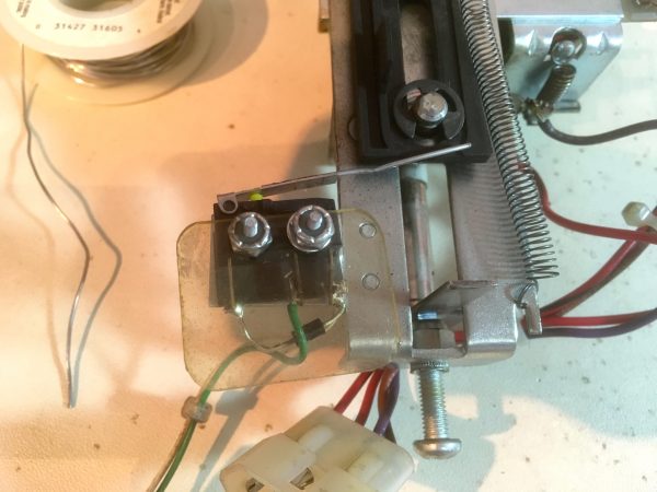
The way it works is that a solenoid pushes it up, against a spring wanting to pull it down. It locks in the up position on a detent. The ball hitting the target pushes it back slightly, knocking it off the detent, causing the spring to pull it back down. There’s also a small electromagnet on the side which can pull the target off the detent. That means the computer can decide which position the drop target should be in by raising it with the solenoid or lowering it with the electromagnet. Very cool! Of course, for this to work, the computer also needs to know what state the target is currently in. This is done with a microswitch at the bottom. The switch closes when the target is in the down position.
Here’s a little video demonstrating the drop target’s action:
Our problem is that the target is behaving erratically in different game modes. In NAS Cure mode, the target should be down, but the computer put it up. If I manually knock it down, the computer fires it up again. This suggests the computer is confused about what state the target is in, which suggests the state switch isn’t reading properly.
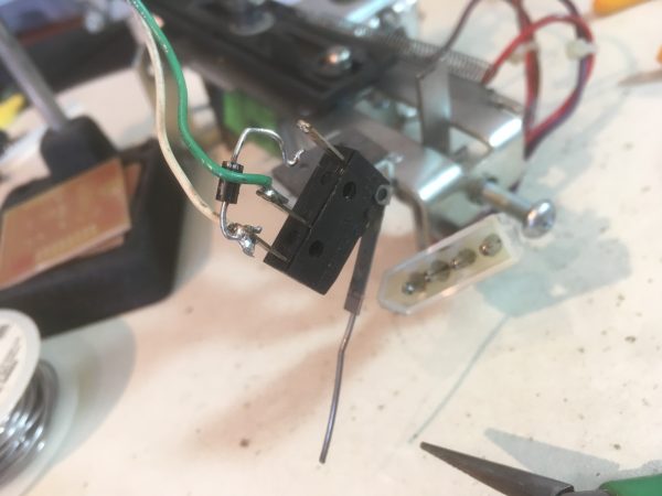
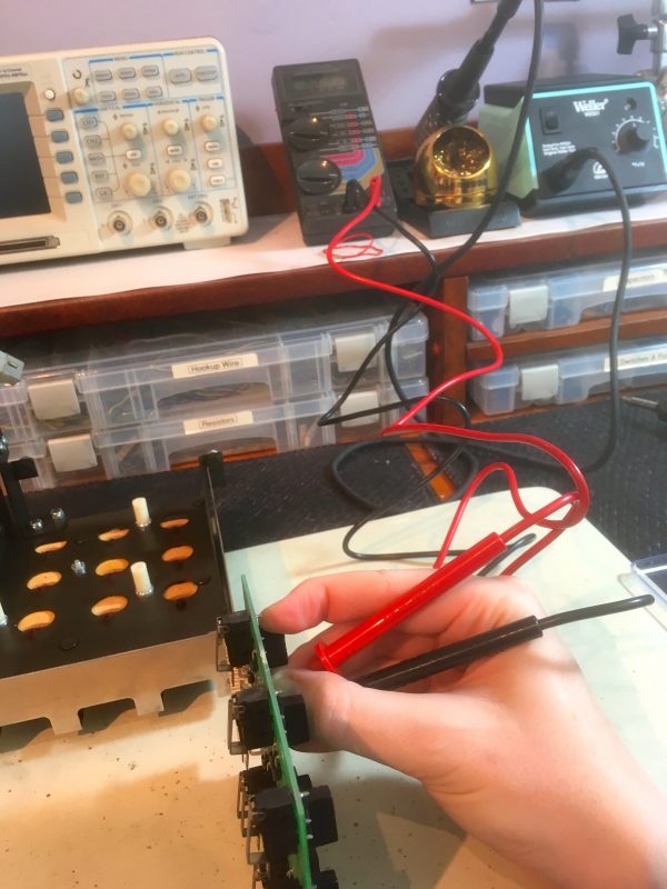
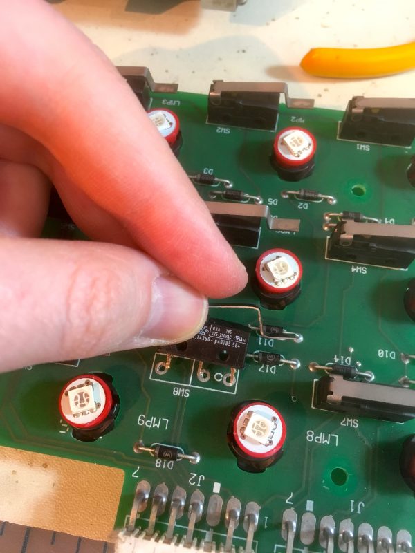
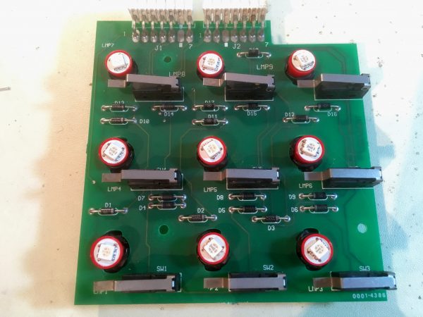
Almost every pinball switch has a diode across it. This is because the switches are matrixed into rows and columns like a computer keyboard. This is an easy way to greatly reduce the number of inputs required to read the dozens of switches on the playfield. When one of these diodes goes bad, it can cause all manner of issues. This usually creates problems with a whole row or column of switches, but it’s worth testing the switch and diode in isolation, just to be sure.
Pretty much everything on a pinball machine is adjustable, which is a good lesson in mechanical design. Nothing in this world quite matches the drawings or behaves the way the simulations say it should, so make everything adjustable.
Next, let’s tackle the glove sensor board. This is an easy swap of the optosensors. You would think that, being solid state and subject to no thermal stress, that optos would never go bad. However any pinball person knows that somehow they do. Of course, that doesn’t mean you should make the mistake I am making here and jump to said conclusion.
Lastly, I’ll take on what I thought would be the easiest fix- swapping the bad switch on the Cyber Matrix. Pinball machines laugh at the best-laid plans of humans.
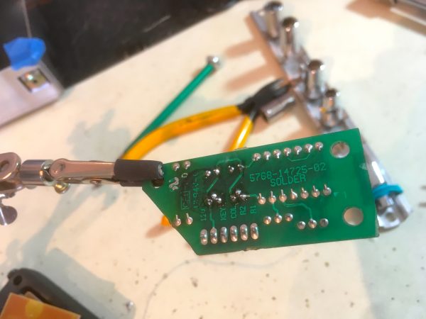
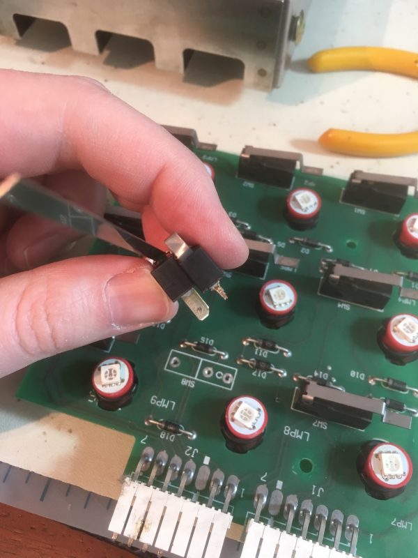
The first step is to desolder the old switch and get the new one ready.
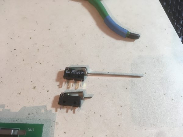
Astute readers may have already spotted two significant problems with the new switch in the above photo. I didn’t notice until I was ready to install the new one that the switch is a solder-lug style, not a PCB-mount. It never occurred to me to check for that when ordering the part. Undeterred, I set out to convert this to what I needed.
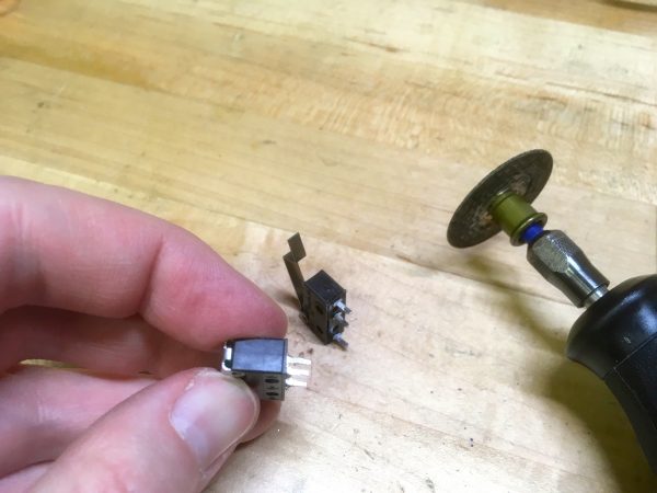
Marco Specialties very graciously replaced the part for me, although the new one was also the solder-lug type, as they don’t carry the PCB-mount style (which are uncommon in pinball machines). My Dremel trick was employed again, and I was ready to go.
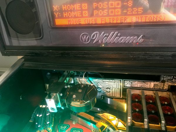
The drop target and the matrix were now working great, but the glove was still having problems. At this point I stopped and put the thought into the problem that I should have originally. The symptom is that the glove, when moving forward (towards the player), would crash into the end of the arm, as though the computer thought the arm was longer than it is. That’s why it throws the “No Y Progress” error- the CPU is signaling the Y-axis motor to turn, but the gantry is physically pinned against the frame, and the optosensor tells it the glove isn’t moving. To understand what’s wrong, we need to understand how the glove travel works.
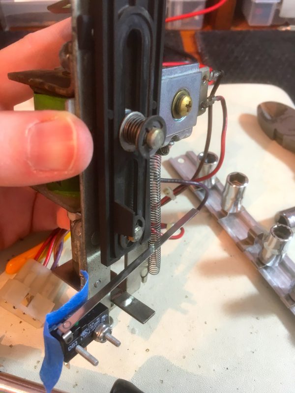
The glove does not have limit switches on the ends, as you might imagine. Instead, there’s a single switch in the middle of the arm that sets the “zero” or “home” position. The computer assumes that’s the physical center of the range of travel, and it counts turns of the threaded rod to measure relative travel distance from that point. It “knows” how long that rod is, what the pitch of the thread is, and thus how many turns it can get away with before it has to stop. If it’s making that fixed number of turns for full motion, but crashes into the end of the arm before it gets there, what does that really mean? It means the zero position is wrong. Like everything else, this is adjustable. The switch that sets zero is actuated by a metal plate on the moving gantry of the glove, and this plate can be adjusted to control when the zero position is registered. The fact that the glove crashes into the front of the arm but not the back means the zero switch needs to be closed a little sooner.
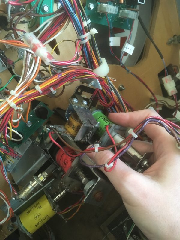
The L-shaped black plate on top of the gantry activates the zero switch. It has a slotted hole that controls the angle of the plate, and this angle controls when the switch is activated. Moving the plate upwards causes the zero-point to move forwards in the coordinate space of the CPU. The silly thing is, I’ve had this exact problem before, and simply forgot that zero-point-drift is the cause. My optosensor adventure was a wild goose chase brought on by jumping to conclusions.
So why did this get out of adjustment, if I had set it correctly before? Well, recall that the huge electromagnet in the glove pulls the ball upwards and into the mechanism with considerable force. Over time, those repeated upward impacts will tend to cause that L-shaped mounting plate to drift upwards, which causes the zero point to drift forwards. Physics!
With that figured out, all three systems were now working correctly once again. Naturally, I had to play a few hundred games in the name of science. It’s important to verify one’s results. For science. Now if you’ll excuse me, I need to go play more pinball do more science right now.
Oy, where is everybody…?
Oh well. Well done, Quinn! 🙂 Also FIRST POST just because I freakin’ can 😛
…I wish I was lucky enough to have a pinball machine in my house. I remember Northgate Mall over in Durham, NC used to have an arcade called “Tilt” in it — ungodly noisy at best, but plenty of fun when my age was in the upper single digits. I had fun there. Of course it’s way gone… heck, I don’t even know if the mall is still there! It’s been a long, long time since I lived in that area.
For a while I had some sort of very lame space-themed tabletop pinball game… got rid of it a while ago tho. It didn’t have much to it, hence the remark about being ‘lame’ — it was the rather Spartan bordering on ascetic lack of traditional pinball goodness, being a very cheap (and poor) imitation of the real thing, rather than the theme, that made it so awful. I eventually got rid of it — it wasn’t much fun and really was kind of pathetic.
I’d try and build my own, but I have basically none of the required skills (I can do the artwork, sure, but the electronics and mechanics are way too advanced for my tinkerin’ skills).
Oh well. At least I can have dreams 🙂
Sorry.
I ramble too much.
Not at all! I welcome anyone to share their stories here. Not sure why the comment thread is so quiet on this one. No love left for Johnny, perhaps.
Thanks for publishing this. It’s been quite a while since I’ve been able to attend a pinball repair session. I miss it. This was a nice trip.
Johnny Mnemonic is not a pin I know how to play. I’ve seen it here and there, but never really got into it. I don’t know that it’s a complex game, but like most pinball machines of that era and forward, there are rules and it pays to know them. Otherwise, it’s just all flailing.
But… I really don’t like it when they can’t hire the original actors as voice talent. Ugh. I don’t recall if these are sound-a-likes, though. Back To The Future has Christopher Lloyd but only a sound-a-like for Michael J. Fox. That’s probably why Dr. Brown’s voice is more prominent in that game. 🙂
Don’t forget this exists!
https://www.youtube.com/watch?v=DjR4HXYjRLg
Yes, that ColorDMD is very cool. I’m resisting because I *just* replaced the DMD in Johnny with a brand new one (before the color one was out for JM). I can’t bear to replace that expensive part again so soon.
I hear you on the sound-alikes. As a huge Buffy fan, I was bothered by the sound-alike Sarah Michelle Gellar they got for the Xbox games. They got all the real cast except her, and you could tell.
For JM, I will say though, that the sound-alikes are all really good. I actually thought Ice-T was really him for years (until I happened to read the credits one day). I think it helps that the samples are all short, mixed with loud music, and are crappy 8-bit compressions anyway. You can tell that Keanu is not real, but his thick surfer-dude accent is so easy to parody to the point where it doesn’t matter. He’s sort of a caricature of himself anyway.
As for complexity, I was speaking mechanically. The rules for JM are fairly straightforward as ’90s Williams games go. It’s no Twilight Zone, but there’s more to it than say, Terminator 2. It’s somewhere in the Road Show/Judge Dredd category I’d say.
I think it’s the Keanu Reeves sound-a-like that jumps out at me. It doesn’t sound like him. I agree with you re: Ice-T. I didn’t know it wasn’t him and probably wouldn’t have known if you hadn’t told me.
Maybe they should have gotten Sean Penn. He could have done Jeff Spicoli which is very much like 90s Keanu, at least how we mostly knew him.
does sprocket ever get up on the machine while you are playing and try to get the ball?
Indeed she does! She likes it up there quite a bit. Sometimes she just flops down on the glass while I play. Observe:
https://mobile.twitter.com/QuinnDunki/status/821067929215123456/photo/1
lol
I am way off topic here, but I just had to tell you I have that same “micronta” multimeter you do. I have had the thing for over 20 years and I swear I have only changed the batteries once. It was my first meter I fell in love with. Thanks for all your great posts, especially the GPU/AVR bit. I have had immense joy following along and building my own version.
My Micronta multimeter is always on topic. I got that as a child in the 1970s or early 80s and I keep waiting for the damn thing to die so I can replace it with a nice Fluke. It refuses! Proof that RadioShack actually used to make good stuff. Also I hate autoranging meters, so I may have to keep it forever.
I’m super glad to hear someone followed the GPU project!! I never imagined anyone else would. Thanks for sharing!