Hey Readers! This post includes the first-ever companion video on the private Blondihacks YouTube channel. To see it, pledge any amount on Patreon. Whether you pledge or not, do me a favor and subscribe on YouTube as well. Many useful YouTube channel features (such as external links) are locked out until a minimum subscriber count is achieved. You can really help me out by subscribing.
If you like the video, please comment about it here on the blog, so other people might be encouraged to sign up on Patreon as well. Thanks!
Now, back to the blog…
Wherein we take our life into our hands.
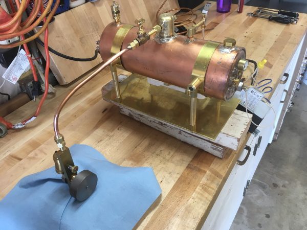
Yes, you read that title correctly. After many months of effort, this homemade-from-scratch electric steam boiler is finally going to make steam. Before we’re done, we’ll learn some sobering lessons about the dangers of live steam.
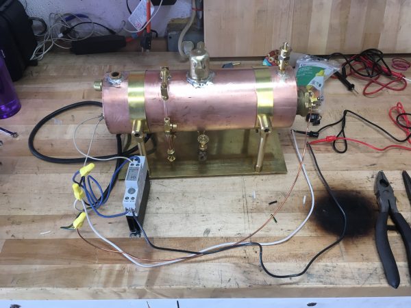
Now that our boiler is pressure-tested and all the accessories are hooked up, we’re ready to add heat to water and cause some trouble. Unlike a traditional fired boiler which would use fuel pellets, coal, wood, or some other combustible, this crazy contraption is “fired” with an electric immersion heating element built into the structure. In order to test making steam, we need to rig up the electrical bits.
One of the things they used to drill into engineers in school is that you should always take notes on your work. This is such a foundation of engineering education that “engineer notebooks” are a specific genre of prepackaged dead trees. The reason for this is that generations of engineers have learned the hard way that you won’t remember all the things you think you will. I was taught this, I knew this, I’ve been burned by this before, and yet…. I ignored it.
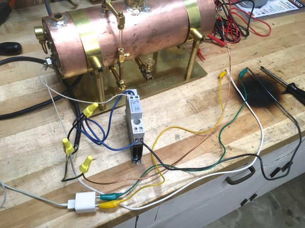
You may recall that way back in the very first post in this series, I rigged up a contactor with my heating element and thermoswitch. I did this make sure the whole crazy system would work, and also to learn how to use a contactor, since I had never done so before. The end result was pretty simple wiring-wise, so I didn’t bother writing it down, confident I would remember how it was done. I suppose I never imagined it would take me seven months to get back to the point where I needed wiring again, but here we are.
What I ended up doing was studying the photos from my own original blog post, trying to deduce how it was hooked up. Unfortunately, the camera angles were not great for this purpose.
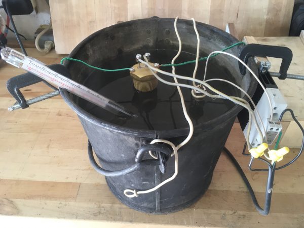
Between the photos and my own long history in electronics, I felt I could deduce how to wire up this contactor. Before risking my expensive (and now difficult-to-remove) heating element, I wired up the contactor and thermoswitch, but substituted my multimeter for the heating element. My reasoning was that if I can get to a point where the thermoswitch toggles on and off at a particular temperature, causing 120V or 0V to appear on the big end of the contactor, I’ll have success.
After hooking everything up, I couldn’t get the desired result. No matter what, the contactor always showed 120V on the output. Strangely, the contactor has an LED on it indicating when the big end is energized, and the LED would go on and off as expected as the thermoswitch changed temperature. It seemed very much like the contactor simply wasn’t working properly. Even when “off”, it was showing 120V on the output. It seemed impossible that the contactor was bad, since it was known to be working before, and had done nothing but sit in a box on the shelf for six months.
This is an interesting example of where your own knowledge and experience can sometimes lead you astray. First of all, I was convinced I knew how contactors work, because they’re basically just relays in terms of hookup. Second of all, I had learned the hard way back on Veronica’s EEPROM circuit that sometimes electronic parts are just dead, even when it seems super unlikely. All this added up to me convincing myself that the contactor had gone bad. All the evidence I had seemed to point in that direction, and I let myself fall into a mental trap about it. I was so sure that I think I even tweeted about it.
Given all this, I dropped another $50 at McMaster-Carr and ordered a replacement. The replacement came in and…. wait for it… behaved the same way. Well, poop.
If you’re experienced with AC machinery or industrial process components, you’re screaming at your web browser right now because you know what I did wrong. Contactors are wired like DC electronics relays, sure. But they do not behave like them! Contactors need a load on their output to function. The contactor does not turn on and off with nothing but a voltmeter hanging off the output. If I understand correctly, this is because the contactor is waiting for a zero-crossing in the AC frequency to make the on/off transition (to prevent arcing), and without a load passing current, it never sees one. Feel free to correct me in the comments if this incorrect. What I don’t know about AC would fill a warehouse, so I’m just guessing here about why a load is required.
However, I still wasn’t emotionally prepared to sacrifice my heating element on this altar of my own ignorance, so I did one more test with a real AC load. I grabbed the closest thing handy, which was…
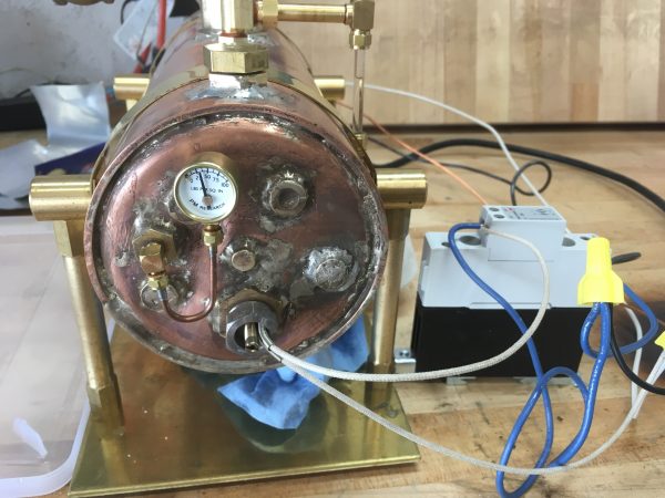
After confirming everything was working, I swallowed my pride, hooked up the real heating element, and tested again. Everything worked perfectly, of course. I had the wiring right all along, and none of this drama was necessary. I placed my fancy extra contactor on the junk pile. I’m sure it will be used for something someday, and I got a $50 education in AC machinery control.
With the electrical sorted out, there was nothing left but to fill the boiler with distilled water, plug it in, and stand back. I timed the progress from cold, for future reference:
• 7 mins: Boiler too hot to touch
• 10 mins: Making noises like a tea kettle
• 13 mins: Water boiling(?) noises
• 20 mins: Pressure gauge starting to read
• 22 mins: Gauge reading 25psi
• 28 mins: Gauge reading 50psi
I can’t overstate how exciting it was to see the pressure gauge read for the first time. Seeing this crazy thing I made making actual steam pressure under its own power was insanely great.
Now, that was exciting, but nothing compared to what is about to happen. You see, this first steam test had a dual purpose. In addition to making steam, I needed to test the safety valve. The top of the boiler has a blow-off valve set to 60psi (10 psi above normal working pressure) and it’s crucial to know that this valve works correctly before trusting the boiler. Not only does a blow-off valve release pressure, but it has to release a sufficient volume of steam to get down to safe levels quickly, and stay ahead of the pressure that is still building. This is a large volume of steam to be released in a short amount of time. I was…. unprepared for this.
I could hear a seeping sound start to come from the safety valve as the boiler got close to 60 psi, so I started filming to capture the moment. I thought the seeping sound was the valve doing its thing. Turns out that was the mountain lion growling at you just before it rips your throat out. Watch and see. Headphone wearers, turn down your volume.
I was completely unprepared for how much steam was released, and the force with which it comes out. Everything in a six foot area was completely soaked, I dropped the camera, and it took me some time to gather myself back up. The good news is, the blow-off valve worked perfectly! All in all, it was a great success and I learned more respect for 60psi of live steam.
With the boiler up to steam, I can test the globe valve that I’m using as a throttle.
Shazam! That’s a very nice blast of hot steam at 50psi. There’s a lot more water there than I’d like, and I believe this is because the boiler is overfull. I have a lot to learn about boiler operation, and I need to get to know the quirks of this boiler in particular.
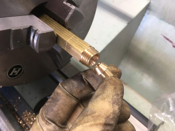
Now that we can make steam, there’s just one more thing we need to run a real engine. We need a steam pipe to connect the engine to the throttle valve. Rather than relying on hydraulic sealant for these connections, I decided to try pushing my skills and see if I could make proper self-sealing flare fittings.
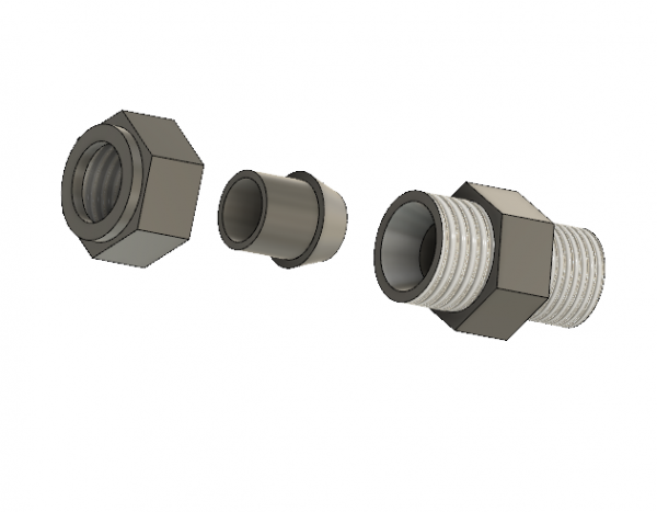
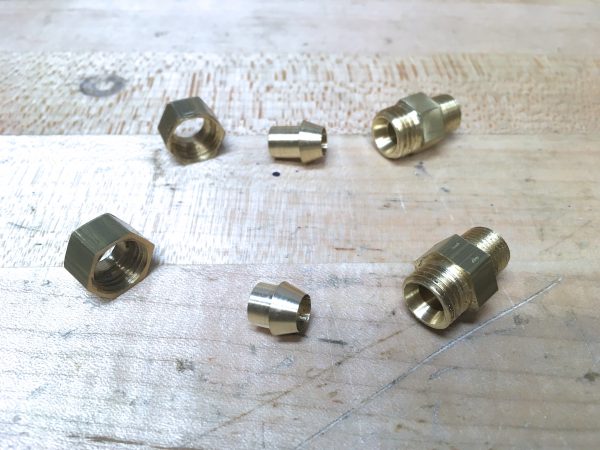
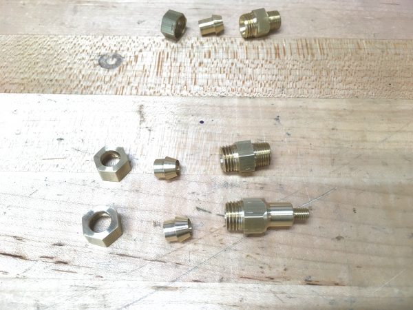
A flare fitting has three parts- a male cone, a female cone (or seat), and a captive nut which holds those tightly together. The actual sealing is done by the cone surfaces being precisely machined and seating together perfectly.
To make sure I understood what I was doing, I modeled the whole fitting in Fusion 360 first.
Looks easy enough. To the lathe!
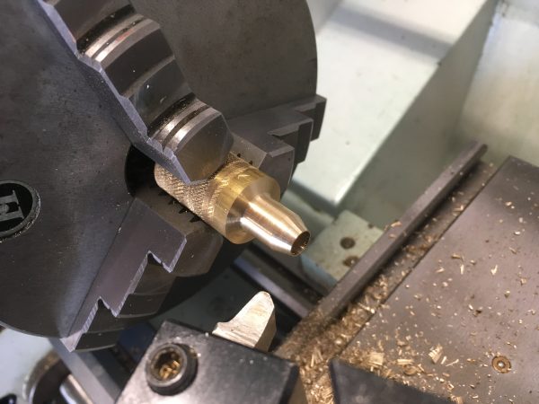
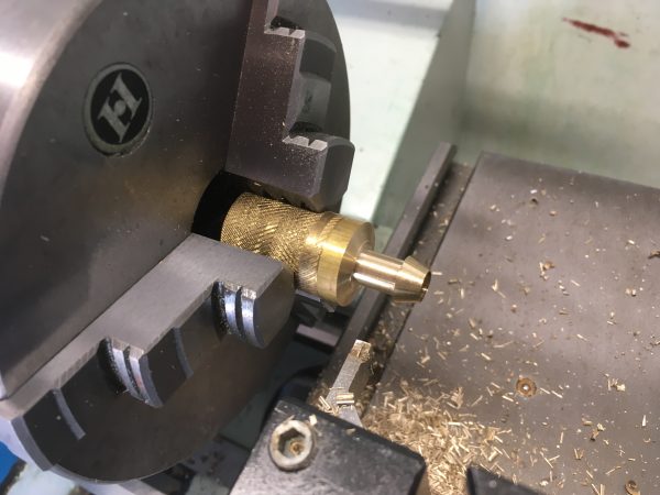
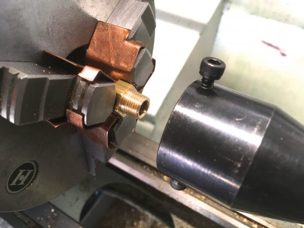
Next comes a great trick that I adapted from a suggestion from a friend on Instagram. Thanks, Rob! The idea is that, after you cut the flare for the cone, don’t touch the compound. Instead, put a boring bar on the toolbit side of the tool post, and run the lathe backwards. Because you haven’t touched the compound, the angle of the mating surfaces is guaranteed to be perfect (not counting spring in the boring bar, chatter, or other incidental artifacts).
With this trick, our odds of success for this fitting sealing properly are pretty high.
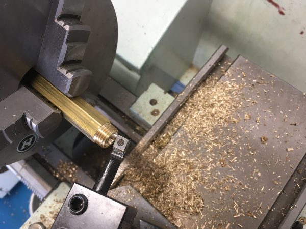
All seemed to be going well, until I came to make the clamping nut. I had modeled everything in Fusion 360 ahead of time, so it should have been perfect, right? Well, I didn’t use the “modeled threads” option in Fusion, so I didn’t see that the wall thickness of the nut was too thin for the depth of threads inside. I tweaked all the dimensions a bit, and made the three parts again.
The engine I’m going to test with is the first wobbler I ever made, so I needed the other end of the steam pipe to fit the 10-32 inlet on that engine.
Through the magic of television, we instantly do all that again.
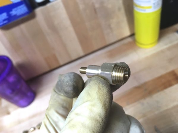
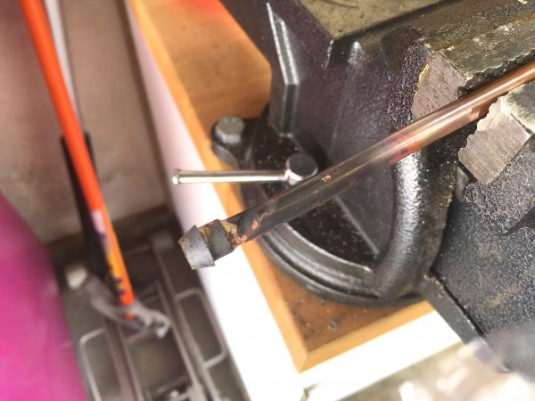
The cones in a flare fitting are soldered to the pipe, and the nuts are held captive behind them on the pipe. It’s time for some silver soldering.
Compared to silver soldering the boiler itself, connectors like this are incredibly, incredibly easy. A few seconds with the Map/Pro torch, and it’s done.
A little cleanup with Scotch Brite, and our pipe is ready for service.
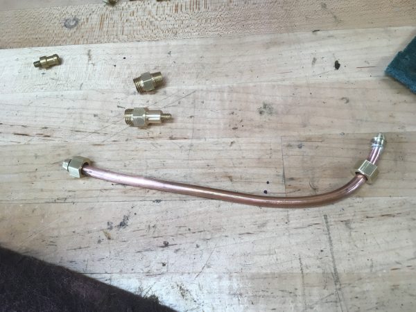
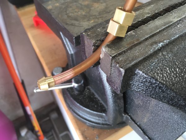
Okay, let’s get it hooked up!
The good news is, both fittings sealed perfectly. I was very pleasantly surprised that neither fitting needed any sealant, and with minimal tightening pressure they sealed 50psi flawlessly on the first try. I’ll definitely be making my own fittings again in the future!
Now I know what you’re thinking. Show us the engine running on steam. Luckily, I have some great video of it, but that’s reserved for Patrons. If you’re a Patron, you already have this video in your in-box. There’s also a little tour of where the boiler is now, and the work that will coming on it.

If you’re not a Patron, this is a great time to sign up because there will be a lot more videos and other perks coming your way! Want some Blondihacks stickers? You can get them over on Patreon. They’re pretty sweet, if I do say so myself.
There’s still a lot more to do on this boiler, including finalizing the electrical work and building the base, so stay tuned for all that!
So during normal operation, how do you keep the over pressure valve from triggering? Do you need to carefully monitor steam creation vs consumption or is the temp probe alone capable of that balance?
That’s a great question, and something I should have addressed sooner. Herein lies the cleverness of D.E. Johnson’s electric boiler design in a nutshell- because the pressure of water/steam depends on the temperature it is at, regulating the temperature effectively regulates the pressure. The thermoswitch sets the “hold” temperature for the heating element. Because there is thermal inertia in the system (changes in temperature take time to be reflected as pressure), there is potential for a tail-chasing positive feedback loop. However, that doesn’t appear to be a problem, and thus this simple thermoswitch-regulated design works well. If it didn’t, you might need something like a micocontroller than can create a hysteresis for the set temperature, rather than reacting instantly to changes as this design does.
On a traditional boiler, you have to regulate the heat manually by controlling the fire. This is the art of the fireman, and in practice the blow-off valve goes off pretty regularly. It’s more of a normal function than an emergency function. 🙂
Nicely done, Quinn, and congrats on getting it working!
I originally happened on your blog looking for reviews on the PM1022V as I am leaning toward purchasing its big brother, the 1030V. I was further overjoyed to find your posts on the boiler as model steam engines are (part of) why I want a lathe; albeit I am leaning toward a propane fired, three-downcomer version of the Yarrow watertube boiler I dreamed up one day.
A question, if I may: If I wanted to *really* slow the spindle down– 6-10 RPM or so– to use a toolpost grinder as a cylindrical grinding machine (I’d also like to do some IC engines and cams are going to be an issue), do you think there’d be room for me to fabricate and install a three-sheave pulley assembly on the motor and spindle hub in place of the two-sheave one from the factory? I emailed Matt, but I haven’t gotten an answer yet.
Thanks either way, and well done indeed…
Dom–
That’s a great question! Let me say overall that I’m very happy with the quality of this machine, and you won’t regret the 1030. This machine turned no detectable taper out of the box and has run like a champ since the day I bought it. The only minor gripe I’ve had with Precision Matthews is their parts department. I recently crashed the power cross-feed and broke the cross feed nut. It took three weeks of confused emails and calls with them to get the part I needed. I don’t regret the purchase for a moment though.
Regarding the pulley, I would say there is room for what you want to do. Honestly, you could replace the current high-low pulley with a low-lower pulley. I’ve never once felt the need for the high speed range, and the manual even says not to use it for cutting (which begs the question why it exists beyond marketing). The machine doesn’t have the horsepower for turning at 2000rpm so you don’t need the high range pulley anyway. I’ll see if I can attach photos here of the drive pulley area so you can see it.
Just so. I guess I can see needing the higher speeds for really small diameters in aluminum or 360 brass or something, but I hadn’t intended to do any of that (or not yet.) Thank you for the answer.
Having now had time to more closely review your video on the pop-off test– thank God that was you and not me; at my age and with my eyesight I’d surely have had my face over it– there’s a quick shot of the sight glass, and I will hazard the guess you are correct and your boiler is overfilled by 3/8ths or the half of an inch. Parenthetically, one of the reasons I wanted to go propane and water tube is there’s room for a steam dryer/superheater in the smoke box although, of course, your indoor use reasoning for electric power is entirely sound.
If taking a bit of water out of it doesn’t fix it, you could always cut the steam dome in half– stop shuddering!– and lengthen it a couple of inches with a piece of copper tube you turned to fit inside the ends of the cut pieces; and thread the stay and lengthen it with a joiner nut. That would allow you to tap steam a good bit higher and, presumably, dryer. I suspect the water you’re seeing is being pushed/splashed up by the steam bubbles rising to the water surface and going through the shell holes under the dome.
Anyway, I’ sure you’ll figure it out.
Dom–
Thanks for the tips on steam operation! I have a lot to learn there, and I’m constantly impressed by how sophisticated the art and science of steam engines is (was?). Reading 100yo books and seeing what they knew about these machines is really interesting.
Here are the pictures of the pulley area that I said I’d get for you:
http://blondihacks.com/wp-content/uploads/2018/09/IMG_9609.jpg
http://blondihacks.com/wp-content/uploads/2018/09/IMG_9610.jpg
The outside surface of the double-nuts on the rods are where the cover sits, so there’s probably room there for a third pulley on the sheave. If not, replacing the two with two different ones would also be easy.
Lol, you have more experience than I. Like yourself, I read 100 year old books and the model engineer boards; and yes, they are quite interesting. Thanks for the pics. Doing a bit of remodeling on the house so I can get a garage/workshop in the back yard, but soon I’ll send you pics of mine. I’m sure you are correct; there’s plenty of room to add another pulley, or one could replace them. I like that little lathe, actually. Especially the variable speed drive. That would make it very easy to CNC, if I decide to, and I am thinking about it 🙂
I loved the video. The intro and ~30 second description was well done. I wouldn’t have guessed this was your first one.
How long do you think the wobbler would run on your boiler at the 5 psi it seemed to be happy at? And what causes it to quit — the water level going below the heat element?
Thank you very much! In a way it wasn’t my first- I spent a few months doing preparation and I made a few practice videos before that one. Hopefully I can continue to get better at this. I’m just using cheap cellphones to record right now, so I’m limited in the interesting shots I can get of the work.
In theory, the wobbler will run forever, as long as the water level is maintained in the boiler. In practice, because that wobbler has no oiling system, it would start to wear out after maybe a few hours if it wasn’t stopped and oiled. My boiler also has no feed pump or injectors, which are methods of adding water while the boiler is under pressure. I’ve added a port for doing that later, though.