When a bolt-on kit…. isn’t.
Anyone who has messed with cars knows that “bolt-on” kits generally involve almost as much custom fabrication as having built the thing from scratch. That’s to be expected when trying to design a kit for a huge range of vehicles of different production years, different countries, and so forth. It’s a wee bit more surprising when the bolt-on kit is sold specifically as an option for a specific machine that you bought specifically with this factory-supplied option. Allow me to explain.
Regular readers know I recently adopted a PM-25MV vertical mill from Precision Matthews. It has proven to be an excellent machine, and I recommend it highly to anyone. I ordered it with the DRO and power feed options, because I knew those would be extremely high return on investment for a mill (and I was right about that- worth every penny). Precision Matthews generally pre-installs factory options for you (as they did with the DRO and the quick change tool post on my lathe), so I somewhat expected they would with the power feed here. Instead, it was included as a kit to be installed by me.
I wasn’t too worried though, as installation should be straightforward, seeing as how this is designed for this specific mill. Let’s see how counting those chickens went.
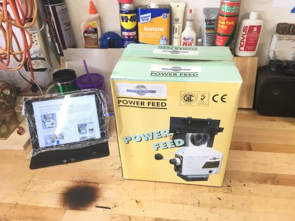
Let’s unpack the box! Exciting toys lie within!
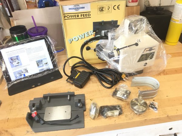
The power unit itself is a Chinese clone of an Align/Bestline “Super Power” electric feed for Bridgeports and similar. The rest are parts to adapt that form factor to this mill. It’s quite overkill for a machine this size, but it’s well designed for the purpose. It has a hefty internal flywheel which ensures smooth consistent feed for good surface finishes.
Right off the bat, we seemed to have a problem. I read through the installation instructions and it was clear this unit would not work, as it hangs vertically below the table. My mill is sitting on a bench (instead of a pedestal stand), so there’s only a few inches between the mill table and the top of the bench. I called Precision Matthews to return it, crestfallen at the prospect of a lifetime of manually cranking that table back and forth endlessly. Incidentally, before installing this, I “did my time” by making one of my smartphone camera mounts without the power feed. Holy cow did that get old fast. If you’re shopping for a mill, I would not consider power feed optional if you want to keep your sanity.
The good news is, Precision Matthews set me straight. This unit does not hang below when used with this mill, it’s just that the included instructions are incorrect. They sent me a PDF link of their special version of the instructions. Including that in the package might have been a good idea, but their phone and email support is helpful, so we got there in the end.
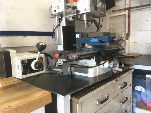
With their PDF on my Saran-wrapped iPad, I got to work.
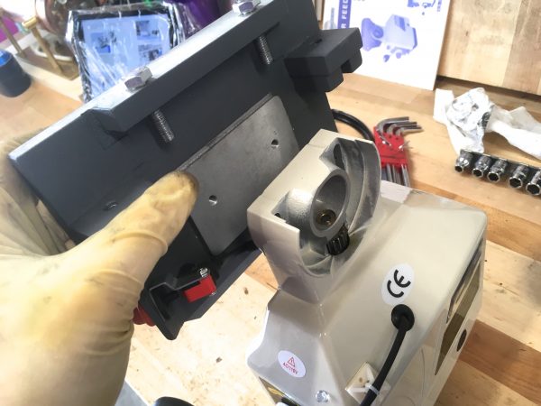
As I mentioned, this power feed unit is designed to hang down below the table. Someone (maybe Precision Matthews, maybe the factory in China) have adapted it to this mill by creating a two-piece 90º adapter plate for it so that it lays flat.
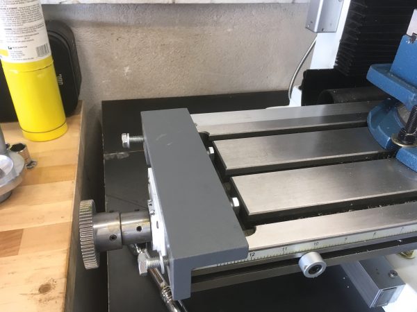
I have one beef to point out with the unit at this point. The way it clamps to the coolant reservoir there means that you lose access to one end of your T-slots. There isn’t enough room to get a T-nut in on that end. You can slide T-nuts all the way down from the far end, but if you have a vise installed, you won’t be able to slide past the mounting bolts for it (on the middle slot). This isn’t usually a problem, since 99% of setups use either the vise or the t-slots, rarely both. However, this has bitten me at least once, where I had to do some weird things because I couldn’t get a T-nut where I wanted one without removing my vise. Not a huge deal, but worth keeping in mind. Another option would be to mill a little pocket out of the adapter plate right where the T-slots end, to give you room to drop in a T-nut. That shouldn’t compromise the strength of the plate meaningfully, and I may yet do that.
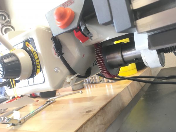
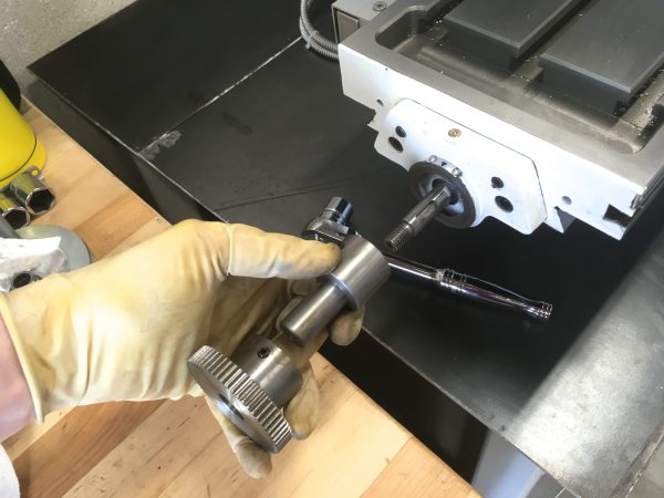
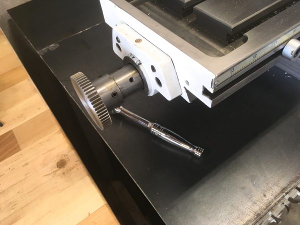
As with any spur gear setup, the next step is a bunch of fiddling to get the engagement just right. People always say to use a piece of paper to set the spacing, but I’ve never had that work well. I go by feel and sound. There’s a sweet spot between where the teeth are bottoming out on each other and the point where there’s a lot of backlash because the teeth are loose. It’s easy enough to feel (and hear) that spot.
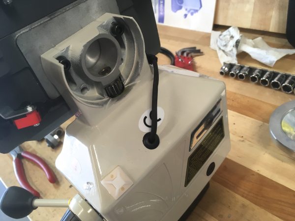
They also provide a cover that snaps over that drive gear, which is nice because it would be quite a meat blender under there. Resting your hand on the bench too close to it might cause everyone to start calling you Old Nine Fingers.
So far so good, right? This baby is installing perfectly. Well, the next step is the limit switches on the table, and here’s where things all went off the rails. Or, off the dovetails, if you will.
The limit switch system consists of two stoppers that mount to the table, and a two-sided limit switch that mounts to the Y axis base (so that it moves with the Y axis, but not the X). The limit switch itself is fairly clever in terms of its simplicity. It’s only one switch, but it has a sliding mechanism such that touches on either side of the housing depress the switch. This eliminates one switch, half the wiring, and a lot of failure points. Good value engineering! Unfortunately, it seems to have been designed for some mill other than the one I bought.
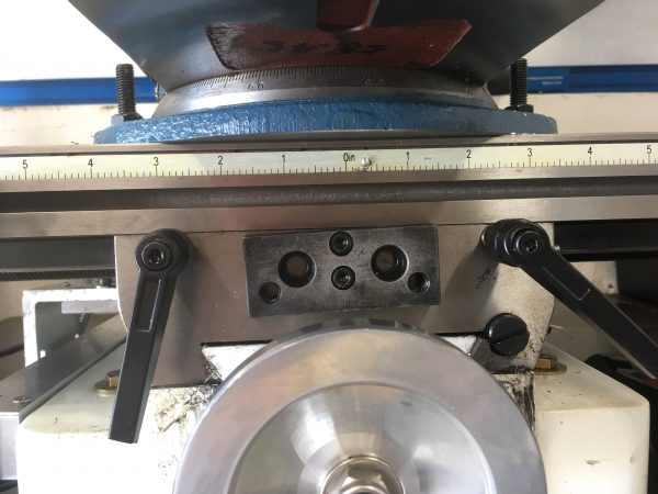
Starting with the basics, the limit stoppers mount to the dovetail slot on the front of the table (intended for milling limit stops, or other accessories). This seems easy enough, except the dovetail mounting blocks for the stoppers are the wrong size.
Next up is the limit switch itself. It comes with a mounting block that goes on the front of the Y-axis slide, and then the switch bracket mounts to that. However, the designated mounting holes on the mill (as shown in the instructions) don’t exist. I could drill and tap the holes into my mill, but I found an easier way.
Cue up the sad trombone player. Ready? Here we go.
I can’t (easily) fix the crooked holes in the table, but I can make the system adjustable. I drilled my mounting block holes a bit oversize to give me wiggle room, then tightened things down once squared up.
Okay, so that was the only problem with mounting the limit switch, right? We’re all ready to go? Don’t go too far, Mr. Sad Trombone Player. We’ll be needing your services shortly.
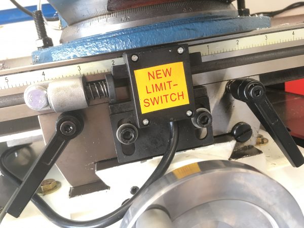
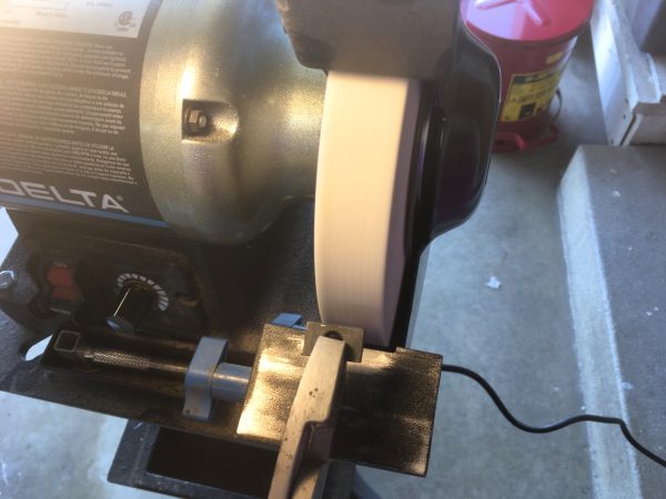
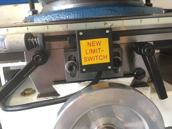
As you can see, with the supplied T-bracket, the limit switch doesn’t really fit. At its lowest position (before it would interfere with the Y-axis) it barely contacts the stoppers, and it barely clears the top of the table (note the vise above it). This might be okay, except there’s a protective cover that needs to go over this thing to keep oil, coolant, and chips out of it.
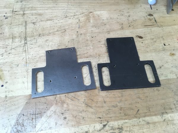
I considered making a different cover for the switch, perhaps with 3D printing or resin casting, but there was basically zero clearance between the top of the switch and the underside of anything bolted to the table. That switch needed to go lower, but the T-bracket was bottomed out. My answer? Make a new T-bracket.
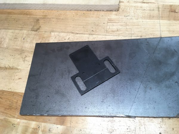
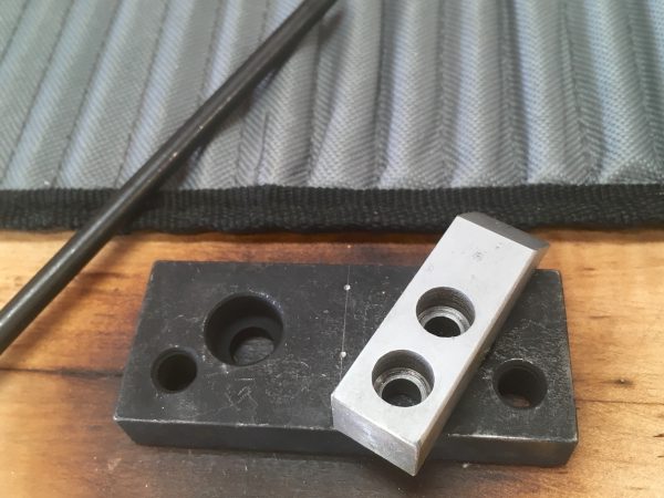
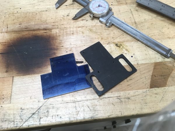
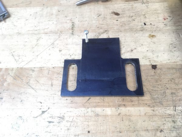
I measured the original, but with the center area shorter. This was marked and rough cut with a portable bandsaw.
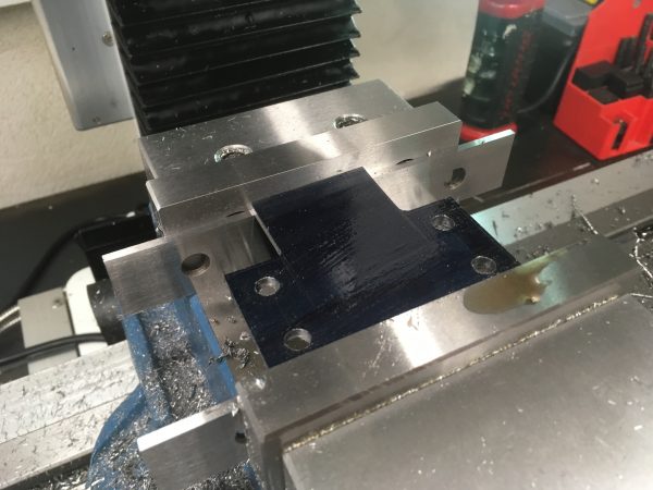
With the part cleaned up, I could lay out the threaded mounting holes for the limit switch, and the large slots that permit adjustment of the height of the assembly on the Y-axis slide.
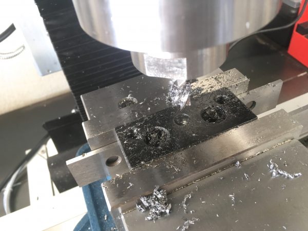
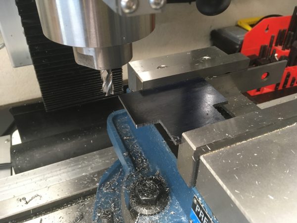
Next up were the big slots in the plate. When slot-cutting, I like to pre-drill each end of the slot with a drill smaller than the final slot dimension. I try to avoid plunging into material with end mills more than necessary, and this way only the outer parts of the flutes are cutting as you plunge.
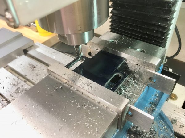
While I had the plate in the mill with the DRO set up, I spot-drilled, tap-drilled, and tapped the four 8-32 mounting holes for the limit switch.
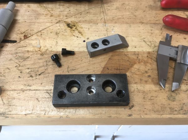
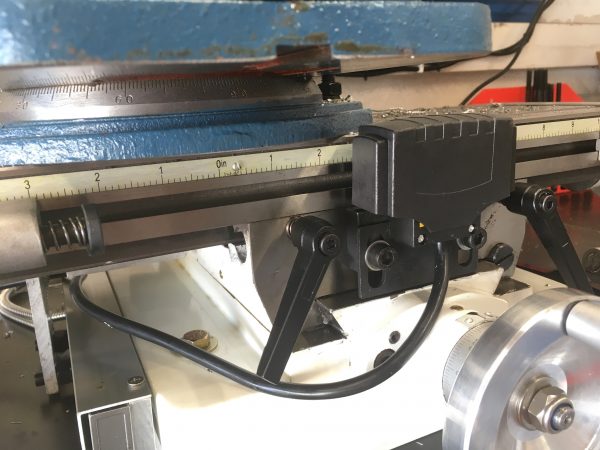
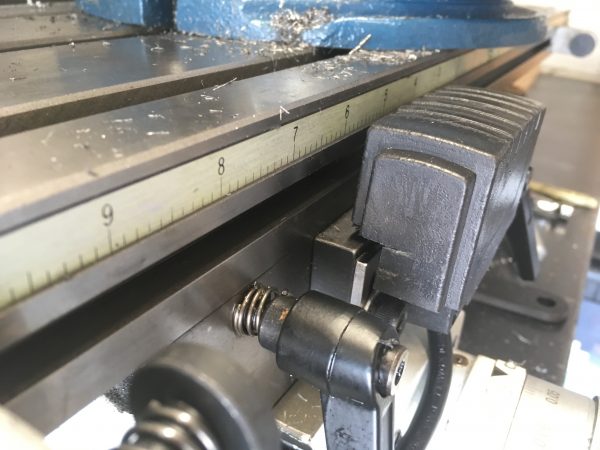
Okay, moment of truth- did it solve my clearance problems?
Okay, slap the cover back on and we’re done, right? Well, noooot quite. You see, the limit switch was designed with the assumption that it would be sitting above the table. As a result, the plastic cover doesn’t fit in this new lowered position. There’s always something.
I ran the power feed back and forth a few times to test the modified limit switch and I’m pleased to say everything worked perfectly. Huzzah!
Despite the some-fabrication-required nature of the kit, I am quite happy with this addition. The speed adjustment is good (if a little touchy), and it will run smoothly at the very low feeds desired for big face mills and fly cutters. It also has a very handy rapid traverse button, which kicks in maximum speed while holding it down. This is just the thing for winding back to the start of the cut for another pass. It also power feeds in both directions, giving you flexibility to do conventional or climb-milling in any orientation on the table.
If I have to pick nits, there would be two:
1) It’s a bit on the loud side. This isn’t a big deal while milling, because it’s running very slowly. It’s quieter than the milling in this case. However when using the fast-traverse button, those straight-cut spur gears really howl, which is a bit annoying. Here’s a video, so you can see what I mean. Subscribe to my YouTube channel while you’re there.
2) While it has a neutral position where the motor is disengaged, you’re still fighting the drive gears when using the hand-crank on the other end of the table. Cranking by hand is not a very smooth experience, and the gears are loud when cranking quickly. I’m considering designs for a clutch of some sort that would disengage the gears completely for hand-operations. Perhaps an idler gear between the two drive gears that can be disengaged when manual feeding.
This was a hugely worthwhile project, and it was fun to use the mill to make parts for itself! This is just the sort of project that makes me love owning machine tools. You’ll see this power feed get used very often in my milling videos, so be sure and subscribe to my YouTube and Patreon, if you haven’t already!
You certainly took all this mess better than I probably would have (but maybe that part’s been edited out of this narrative)! Congratulations on your deft recovery from so many issues.
I’m probably missing something obvious, but why didn’t you just drill and tap some new mounting holes into the original T-bracket, and then trim off the excess top part? Wouldn’t that have saved you a bunch of work over making your new one? Sorry if this is too naive a question.
Excellent question! There are two reasons, one that is mostly rationalization and one that’s definitely real. I didn’t want to modify the original kit in case my idea had some problem I wasn’t foreseeing. I might need to return it, or do something different with the parts. That’s the rationalization. The real reason is that I wanted to see if I could make the part. 🙂
That “real” reason is one I’d already thought of, having followed you for a while… 🙂
Pavel as in LambdaMOO? Cool to see you here.
>This was all mostly unnecessary, but made me happy.
There’s a certain satisfaction in the process of making chips that helps erase other people’s previous bad decisions.
The result looks great.
And, hey, it looks like it’s time to try cutting helical gears, to reduce the howl!