Making improvements to a tool we built
A while back, I built a couple of smartphone mounts for tripods, based on a design that came to me in a whiskey haze. That design worked very well at the main thing it was designed to do- hold a cellphone. However, in practice it has one decided weakness. Any time you attach a camera to something, you need to consider how the camera will be aimed. In my case, the thought was that the NOGA arm will be doing all the pointing, so the camera mount can be static. In practice, that didn’t work very well because the weight of the camera tends to loosen the threaded attachment point, and it’s often inconvenient to have to loosen the entire NOGA arm to rotate the camera.
If you’re not familiar with NOGA arms (or the copies thereof), they are a three-jointed arm with a single knob at the “elbow”. You can loosen the knob, arrange all three joints anywhere in space that you want, and then make the whole arm rigid in that position by tightening that single knob. They are pretty magical. Internally, they work in one of two ways. Some models have cables that run through the joints away from the elbow, and the knob acts as a sort of “winch” to tighten both of them at once, locking all the joints in position. There’s another approach whereby the whole arm is filled with fluid, and tightening the knob eliminates all air space from inside the tube/joint system, effectively locking everything up hydraulically. Both approaches work well. NOGA arms are used in machining, photography, and various other applications. In machining, they are typically attached to a magnetic base, but you also see them bolted to other equipment, or clamped to things.
Here’s an example of how “version 1” of my camera mount worked when attached to a large NOGA arm:

However, here’s the problem:
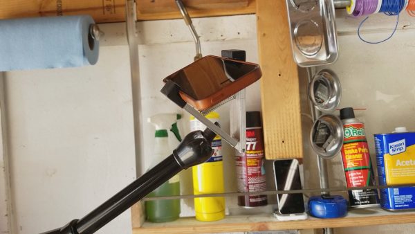
The problem is that the smartphone holder is effectively a long lever that gives the weight of the phone a lot of advantage over the mounting screw. No matter how tight you make it, it will always tend to unscrew itself any time the phone is held in a position where gravity would pull it to the left (lefty loosey).
A jam nut in there might help, but the other problem with this setup is that setting the camera angle is a bit inconvenient, as I mentioned before. It’s also worth noting that standard tripod threads are ¼-20, while the large NOGA arm end-effector has an M6 thread in it. These are obviously incompatible. I had “solved” that temporarily by re-cutting the threads to ¼-20 on half of an M6 bolt. Don’t do this, it’s dumb (though it did actually work).
What I’d really like is a way for the camera to be securely attached to the arm, but still be able to adjust it in space, while simultaneously adapting those mismatched threads to each other. Here’s what I came up with to do that.
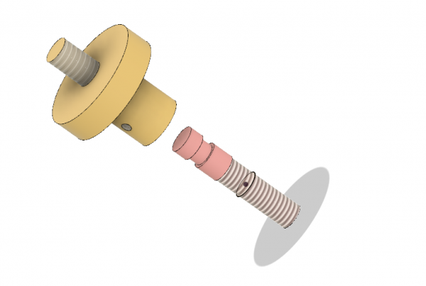
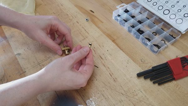
This adapter consists of an M6-threaded rod that goes into the NOGA arm (and can be jam-nutted or Loctited as desired). This is shown in pink in the model. The other end is a smooth shaft with a channel in it. That channel holds O-rings for friction. A knurled knob (shown in yellow) fits over that shaft and is secured with setscrews. The knurled knob acts as the jam against the smartphone holder, while the smooth shaft inside allows the whole assembly to be rotated freely. The friction of the O-rings (with tension set by the setscrews) holds the phone in any orientation. The back of the knurled knob is threaded ¼-20 for fitting into any camera mount (in this case, my smartphone holder).
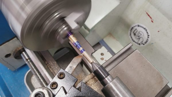
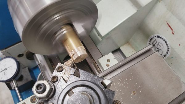
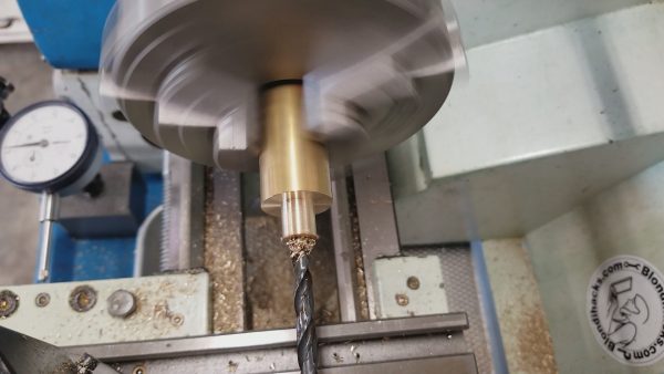
Okay, so that seems sane enough to work. Let’s give it a go. I’ll start by making the shaft that goes into the NOGA arm.
While I’m using brass, anything would work- steel, aluminum, headcheese, whatever you have. Well, headcheese would go rancid pretty quickly, so maybe don’t use that. Also, while I haven’t done a finite element analysis on it as of yet, I suspect headcheese would present some structural integrity challenges. Your mileage may vary.
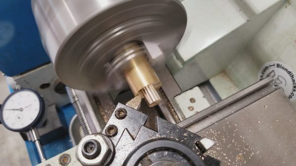
Next we need to make that little groove that holds the O-rings.
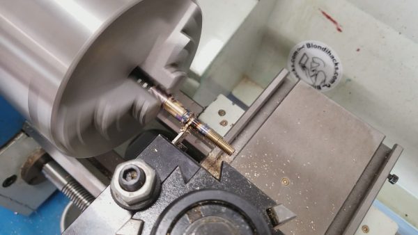
The shaft was turned to the diameter needed by the smooth part of the shaft, but now we need to make the M6 thread. The major diameter of an M6 thread is 236 thou (6mm, shockingly), so we need to turn down that area a smidge further before cutting the threads.
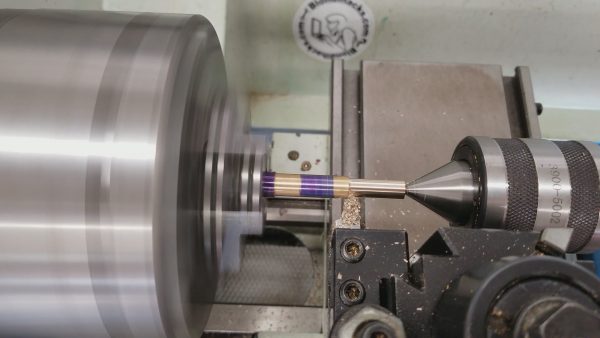
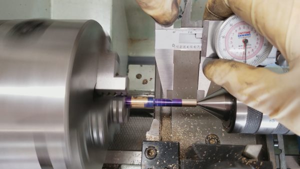
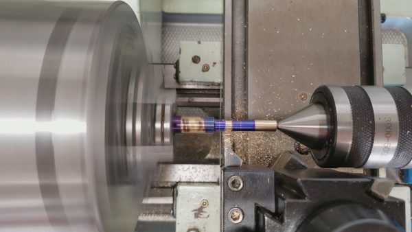
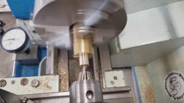
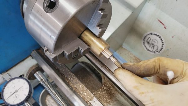
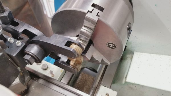
Next up is making the M6 thread. I would normally do this with a threading die in my shop-made tail-stock die holder. However, that die holder is for round dies, and the only M6 thread die I have is the hexagonal style. Fun fact- most online sources will swear that all hexagonal dies are for thread-chasing (repair), not thread cutting. This is not true. There are genuine thread-cutting dies in the hexagonal form factor. Generally thread cutting dies are round, yes, but it goes to show that most things you read on the internet are wrong. Including everything I say, perhaps. In any case, this is a good excuse to show a method of cutting threads on the lathe that doesn’t require a fancy tool. You can do it with almost any die wrench.
The trick here is to put a little chunk of wood down on the ways to protect it, then allow the die wrench’s handle to rest on that. Then you can turn the lathe chuck by hand, and the threading operation will pull the die wrench forward with it, sliding along that chunk of wood. I cut all my threads this way before I made my tailstock die holder, and it works just fine. The trick with the block of wood keeps you from needing three hands for this.
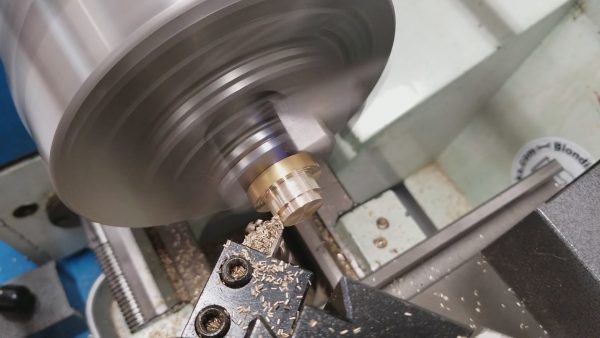
Now we can turn our attention to the knurled knob. That part starts with a bigger chunk of brass.
With the outer shape of the knob formed, the next task is to make the hole in the middle. We want this to be a nice slip fit over the shaft that we made earlier. When designing parts like this, you need to think about two things:
1) What tooling do you have? If you have a standard set of reamers, don’t design a feature with a 317 thou hole, because you won’t have a reamer in that size (or even a drill, for that matter). If the hole is large enough, you can use a boring operation to reach any desired size, but the hole has to be big enough to get a boring bar into. Turning can always be done to any diameter, so make your holes a standard size, and tailor the shafts that go in them to the type of fit you need (press, slip, free-running, etc). If you have over/under reamers, that makes life a lot easier. These are reamers that are 0.5 or 1 thou over (or under) their nominal size. They allow you to easily create light press fits or slip fits.
2) What is your order of operations? Holes in certain places can only be made certain ways. If the hole is coaxial with a round part, it’s likely you can ream or bore that hole as needed. If it’s a cross-hole, boring will require a very complicated setup with a faceplate, or expensive tooling like a boring head on a mill. It’s much easier if you can ream cross holes, so plan ahead for that and make your cross holes standard sizes.
The typical Machinist Way™ to drill a hole is to center-drill (insures concentricity), pilot drill (keeps tool pressure down and larger drills on-course), drill under-size (for reamer clearance) and finally ream to final dimension (for precision). Some of those steps can be skipped, depending on how precise the result needs to be. In our case, the hole is small, so we can skip pilot drilling, at least.
When planning order of operations, always think about the time invested in the part at critical points. If this hole had been 20 thou oversize somehow (machinist error) the part would be useless. However, we’re only on the second or third operation, so it’s not a lot of lost time. Try to arrange it so the most difficult and most critical steps are as early as possible in the order so you don’t lose much time if you have to scrap it.
Now we can flip the part and form the features on the other side of the knob. You’ll note that I’m flipping the part in the three jaw chuck here, which is a giant no-no for maintaining concentricity! Machinists are hurling invectives at their monitors right this very moment! How dare I disgrace precision this way! Okay, everyone take a deep breath. We must always consider whether maximum precision is necessary for any feature. If a tripod adapter that holds a cellphone and will never spin much at all is out-of-concentric by 5 thou due to flipping the part in a scroll chuck, I guarantee you the sun will still rise in the morning. Everyone take a deep breath and step away from the online machinist forums for a bit. Precision is almost always a tradeoff for time, and I dunno about you, but my time on this earth is the only truly valuable thing I have. If I can save some of it in a goofy side project like this, I surely will.
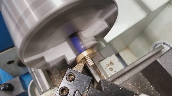
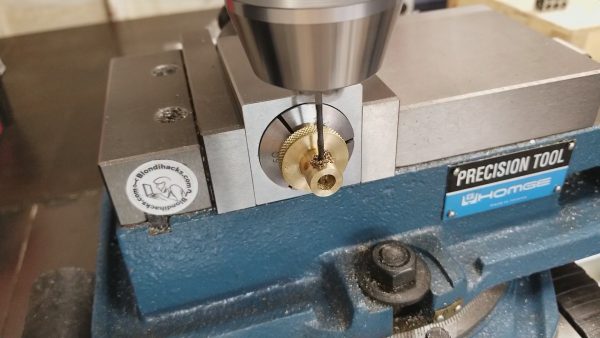
All that’s left on this part now is to cut the ¼-20 threads for the tripod mount. Luckily for this I do have a standard round die, so I can use my tailstock die holder (which was super fun to make, by the way).
Next up is to apply knurling to the knob. It’s not that this knob will see much handling (you screw it into the phone holder once and pretty much never touch it again) but knurling looks nifty. It wouldn’t be a proper machinist project if something wasn’t knurled. Machinery’s Handbook (30th ed.) actually requires all parts to have something knurled. Yes, it’s true! Prove me wrong by reading the whole thing. I’ll wait.
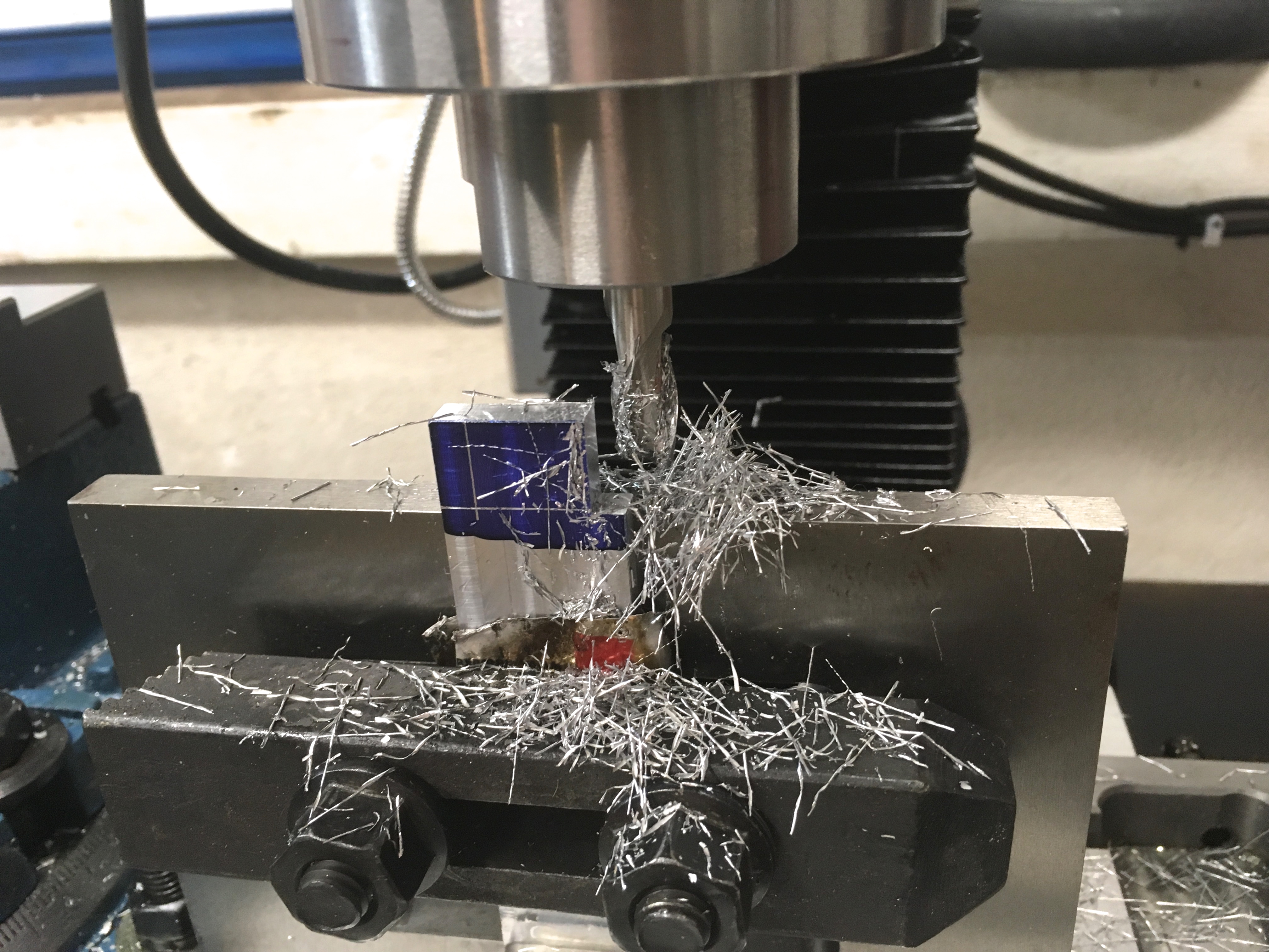
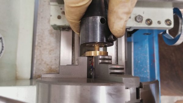
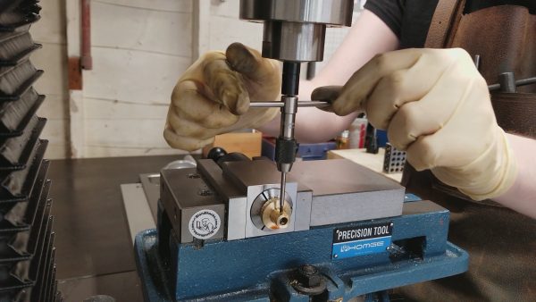
All we have left to do is make threaded cross holes for the set screws that hold this whole thing together. For that, I’m going over to the mill, and using one of my favorite toys: the collet block.
These set-screws are small (4-40, which is about ~2.8mm for Metric folks), so the tap is small too. Small taps means high risk of breaking them, but luckily this is just brass. A broken tap is always a sad moment, because they are so immensely hard that not much can remove them. You can’t drill them out with regular drills. Sometimes carbide drills work, if you have one the right size. In the worst cases, only Electrical Discharge Machining can save you. My $40,000 EDM machine is out for repair, so I’ll just tap carefully.
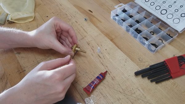
Okay, we’re ready for some final assembly! I made the bold claim up front that this device holds the phone securely at any angle, so let’s recap how it actually does that. The answer is friction. That groove we cut in the central shaft holds some number of O-rings, which provide friction on the spinning mount. You can also tighten the setscrews as needed to set the tension. The set screws need to be in far enough to keep the knob from pulling off the shaft, but beyond that they set the amount of drag on the O-rings. You can also vary the number and thickness of the O-rings as needed for the weight they need to resist. Eventually these O-rings will wear out, but you can easily replace them by backing out the setscrews. The setscrews are not tightened all the way in, as they would lock up the shaft and crush the O-rings. Instead, they are adjusted as needed, then Loctited in place so they won’t back out. If you ever need to remove them, a little bit of heat is all that is needed to release the Loctite.
I’ve been using this knob on my NOGA arm for quite a while now, and I can say it has been working quite well. I did need to Loctite the ¼-20 thread into the phone holder, because it would still unscrew itself over time as the phone was manipulated. A jam nut would also have worked here, but I like Loctite. It’s easy and it works. It remains to be seen how well the O-rings will hold up over time, but it’s been several months, and so far so good. While I designed this specifically for NOGA arms, you can easily change the thread on the shaft to allow you to mount a camera on anything you want. The power of this little guy is that you can thread in the camera mount without needing to rotate the other end, and it will hold the camera at any angle without any threads loosening.
That’s it for this project! Check out my YouTube channel to see lots of videos filmed with this very adapter!
Timo of Hydraulic Press Channel used a similar technique for threading. Great machinists think alike! https://www.youtube.com/watch?v=FKtHn8BVwnw&feature=youtu.be&t=564
Wow, I wouldn’t do it under power like that, but I’m sure he knows what he’s doing. 😀 Fun video- thanks for sharing!