
Pinball machines have a lot of switches, and they fail a lot.
What’s this? Another Johnny repair article so soon? Well, like many complex electro/mechanical systems (cars, robots, robot pets, robot cars, pet robots, etc), pinball machines pout occasionally. It’s often triggered by extended neglect, as many things are slowly degrading all at once. However, sometimes problems are also triggered by, well… me. Allow me to explain.
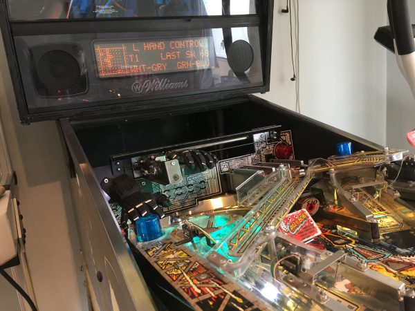
While enjoying several celebratory games following the previous Johnny repair, it became apparent that the left rear flipper button was not functioning. If you’re not familiar with Williams Johnny Mnemonic (and why would you be familiar with a 1993 pinball machine about a terrible movie based on an okay short story by a brilliant author who created the genre of Cyberpunk), there are four flipper buttons, but only two flippers. The rear two flipper buttons are there to control the infamous cyberglove toy. This is a prop from the movie that is part of the interface to one’s cyberdeck, which is used to interface to The Matrix. Yes, in the 1980s, we were pretty sure the internet was going to be all VR and haptic controls. Web browsers would be deeply disappointing to teenage me, I can tell you. Anyway, the glove toy catches and holds the ball when you do certain things in the game. You then gain control of the arm (which is, to be fair, a goddam robot because pinball machines amazing) and can carry the ball across the play field to “The Matrix”. The Matrix (so-named long before a certain Canadian surfer chap donned a leather trench coat) is a grid of nine slots that can hold a ball. There are various complicated strategic reasons for choosing where to drop the ball, but the point is that the glove moves in four directions, hence the four flipper buttons.
Back to my main point- it became clear during play that we could not move the glove backwards, which means the right rear flipper button seemed to be dead. I had some time, so I tore into the problem.
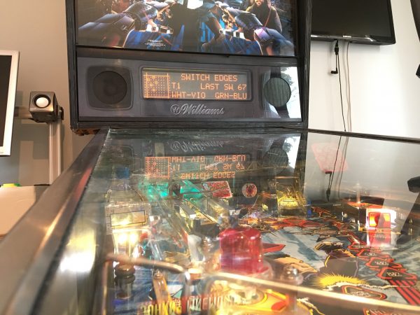
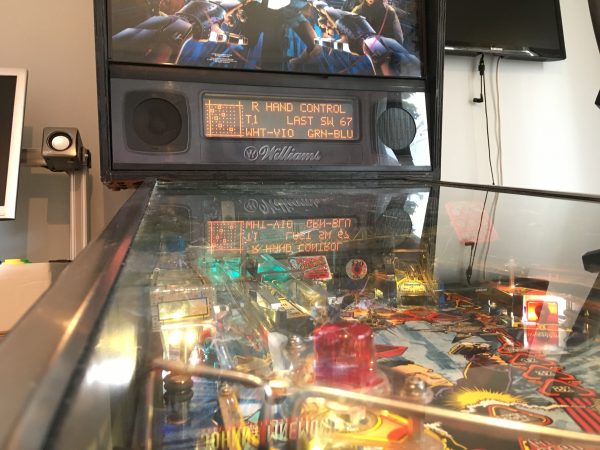
Learning from previous mistakes, I started immediately with the switch diagnostic menu. Sure enough, it confirmed there was no response being received by the CPU from the problematic flipper button.
At this point there was nothing left to do but crack open the machine once again and start poking around. Thankfully, I remembered to remove the balls this time.
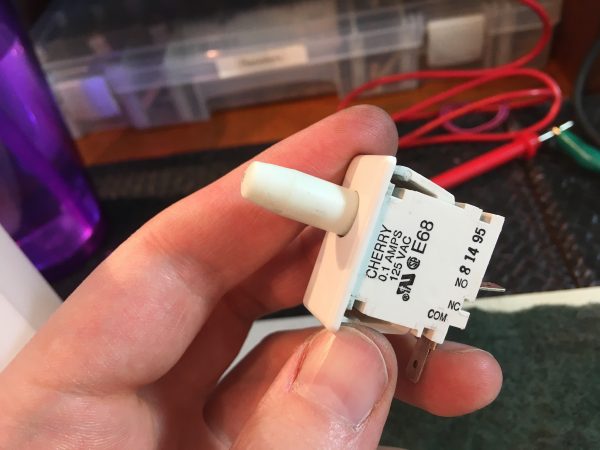
An interesting thing about the rear flipper buttons on this machine is that they are leaf switches. That’s unusual on a machine from this period, when they had mostly gone entirely to microswitches. Purists say that leaf switches have a better feel, especially for flipper buttons, so you might say that’s the reason. However, the actual flipper buttons on this machine are two-stage optical sensors as part of the Williams Fliptronic II semi-analog flipper system. So why bother putting leaf switches on fake flipper buttons that are only used to control the glove? Your guess is as good as mine. I guess it does make them feel the same as the other flipper buttons, since the opticals don’t have the “clickiness” of a microswitch. Maybe I just answered my own question. Perhaps my guess was better than yours after all.
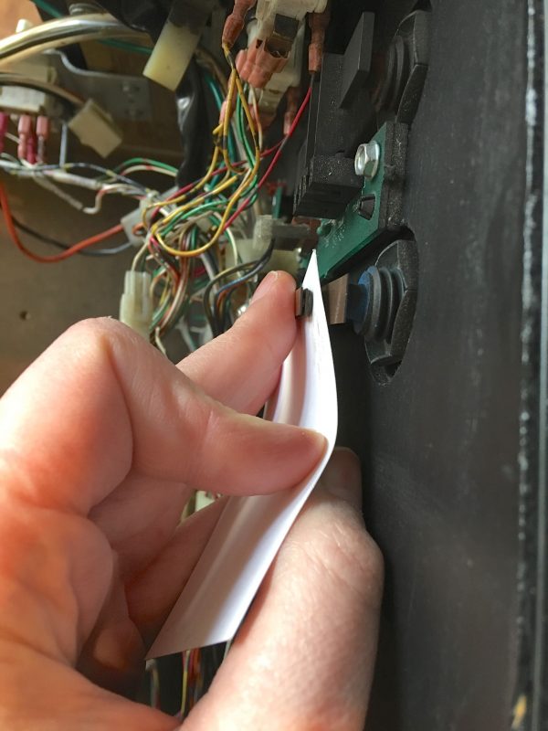
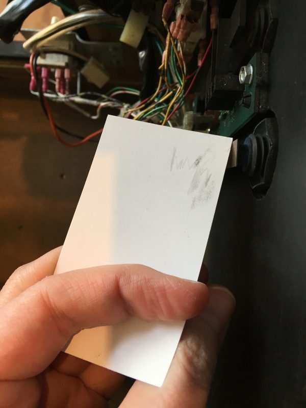
Anyway, back to the problem at hand. Leaf switches are exposed to the air, so they do tend to get dirty a lot. That could explain our malfunction here, so the first thing to try is cleaning it.
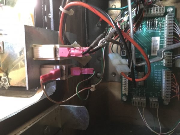
It wasn’t fixed. Time to start looking at wiring. Expecting another marathon adventure, I got out the schematics, harness routing charts, multimet…. oh. Crap.
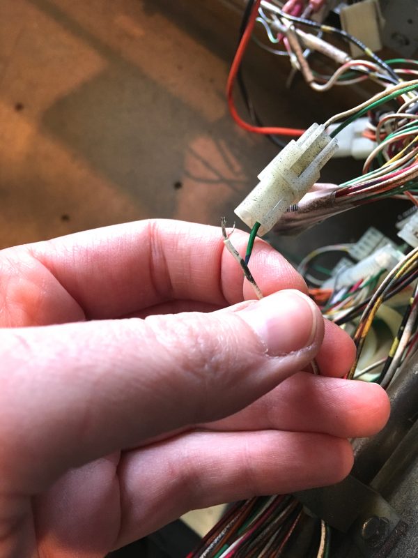
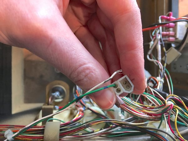
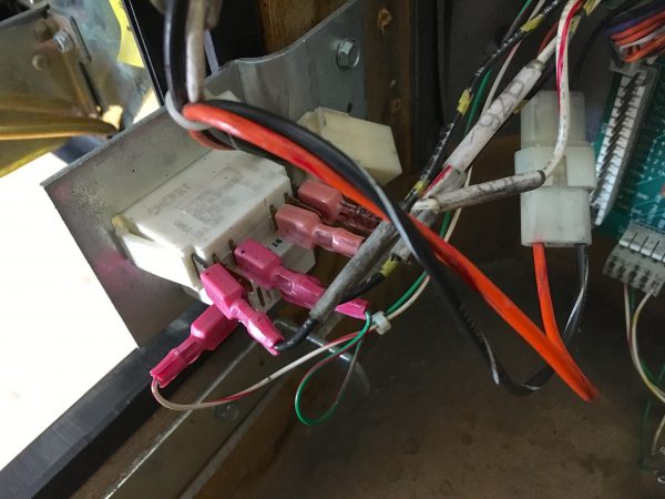
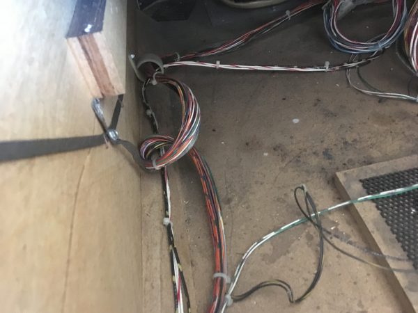
Indeed, following the harness back a bit, we immediately find that a wire has been ripped out of the connector. Unfortunately, I would later realize this was my fault. When I did the Start Button repair previously, I forgot to do one thing at the very end- put all the harnesses back in their retaining clips. I remembered this after the fact, and thought, “oh well, it’ll be fine. I’ll tidy up next time I’m back in there”. It turns out those clips aren’t just for tidiness. They keep some of the harnesses (like, say, the flipper buttons) clear of the runners on the underside of the playfield. When I closed the machine after that job, I probably snagged the harness and ripped it out. You don’t use those rear flipper buttons all that often, so it took a while to notice.
Now I had some choices to make. I am set up for re-pinning most types of pinball connectors, but not this kind (wouldn’t you know). I could order the connectors, the pins, and the (no doubt stupidly expensive) tool to make this type of connector, or I could do something else. I opted to do something else.
A person could simply cut that connector out and solder the wires back together, but that person would be a horrible monster that I would not have a beer with. That connector is there for a reason, and eliminating them always comes back to bite you later when you try to remove some unrelated component and that harness is in the way. You’ll find out the hard way why some 1995 grunge-rock-listening engineer put it there. No, we won’t eliminate the connector. Instead, we’ll make a substitute connector of sorts.
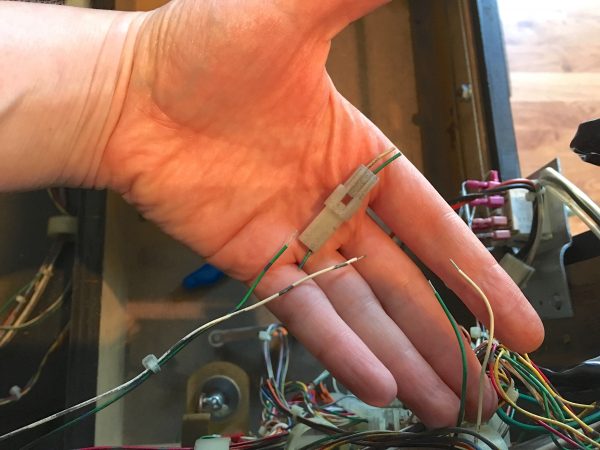
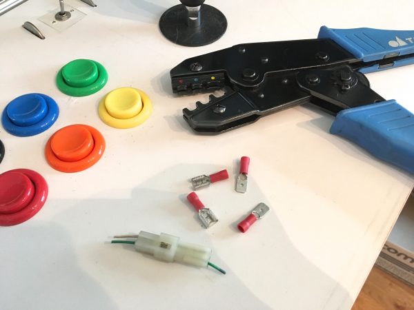
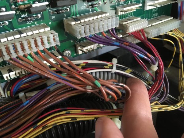
Since it’s only two wires, I’m going to replace the connector with spades. The ideal thing would be those insulated spades as are often used in cars. I don’t have any of those on hand, but we can make them. Allow me to demonstrate.
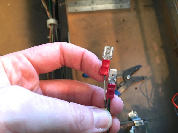
Note the trick I used there- the wires are staggered in length. This is an old racer’s trick to help prevent shorts. Should the wrapping on the connector ever fail, this is still unlikely to short, because the two connectors aren’t aligned. It also makes harnesses smaller because you don’t have a big “ball” where all the connectors are. Now to insulate those connectors!
In a pinch, you can make insulated spade connectors with heat shrink tubing. The trick is get the length just right.
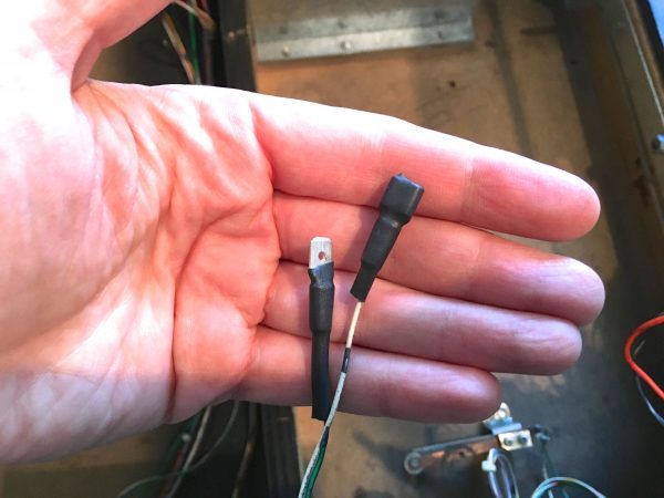
With the heat shrink applied as shown in that photo, the rubber will push itself out of the way as you join the connectors, forming quite a decent seal. It’s not water tight, but it certainly won’t short on anything, and can still be separated at any time (unlike if you had heatshrinked the entire connection at once).
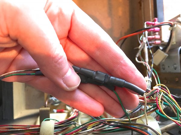
Okay, with our field-expedient connector complete, how did we do?
That’s all well and good, but one more thing was nagging me. While playing, I started getting brief flashes of the Interlock warning. It means the computer is losing the connection to the coin door interlock, and thinks the door is open. In response, it shuts off the high voltage circuits, such as the solenoids. However, the door isn’t actually open, and the problem is quite intermittent. This happened once before, but the problem at that time was the corroded connector on the CPU board (same as the Start Button problem last time). I felt pretty good that the CPU connector wasn’t the problem this time, because I had just cleaned it quite thoroughly. Seems like something else is afoot here. Maybe this time it really is the switch?
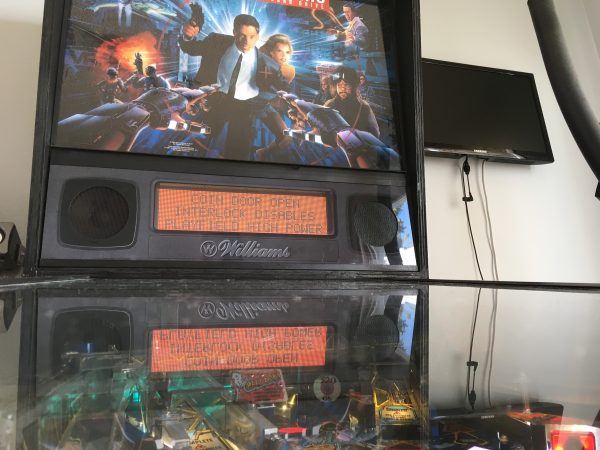
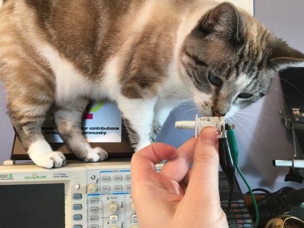
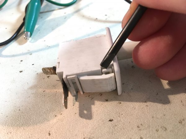
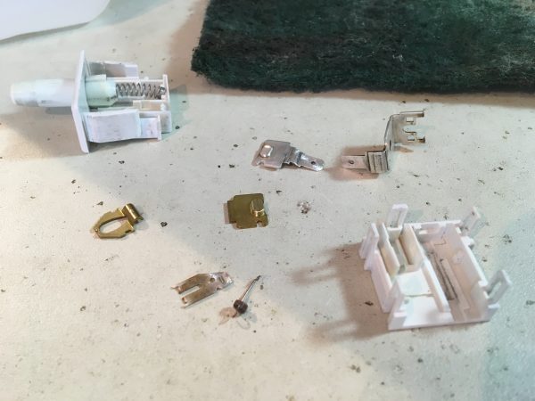
I did check this switch using the diagnostic menu, and it seems okay. The problem is intermittent, which suggests corrosion somewhere. Let’s get a look at that switch.
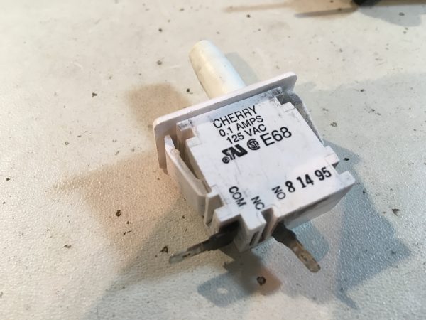
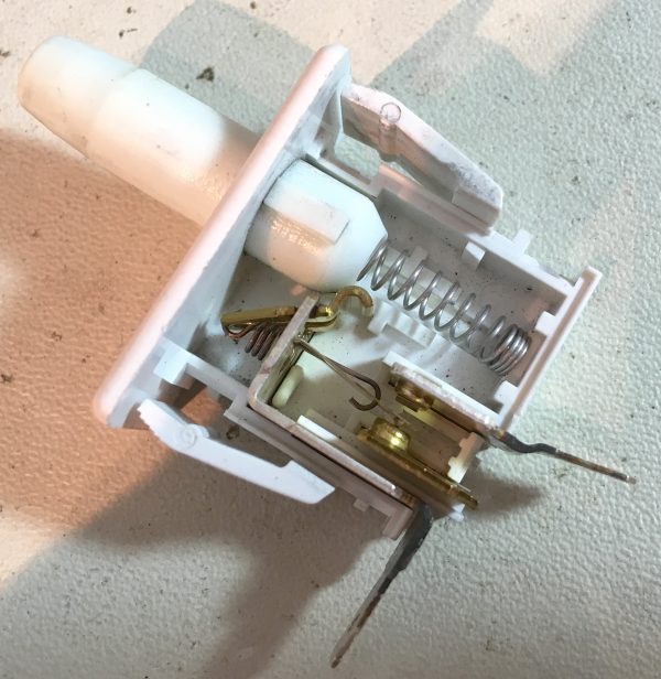
The contacts on the switch are plenty corroded, so this could be our problem. I wasn’t able to reproduce the issue with the multimeter, but intermittent switch problems can be hard to diagnose this way. If your first instinct was to take that switch apart and see how it works, well, you’ve come to the right blog. Welcome to your people.
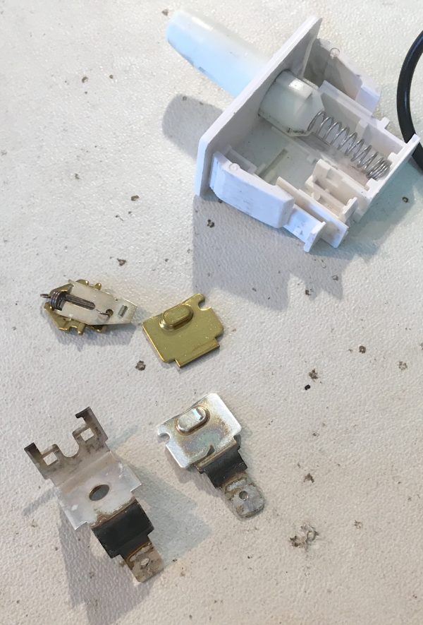
I cleaned up all the contacts with some scotchbrite and alcohol. Contrary to my usual advice of not invoking solutions until you’re sure of the problem, in this case the problem won’t reproduce on the bench, so I don’t have much choice. I’m also lazy and this blog post is already getting too long.
Well, I’m pleased to say that after reassembly, the problem seemed to go away! It did seem to be corrosion somewhere in that system of connectors and contacts. Cleaning the insides of the switch was probably unnecessary, but it was fun.
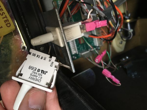
There was just one more thing. The last time I had this area apart, I remarked on that other interlock switch that sits above this one. Once again, I wondered what the heck that is. It isn’t mentioned on any schematics, parts lists, or assembly diagrams in the manual. Yet it has four Very Important™ looking connections on it. What is this switch doing? I needed to know. I checked the switch diagnostic menu, and this switch doesn’t register. So it’s a standalone, not plumbed through the CPU. Time to trace some wires.
The harness disappears inside one of the conduits that runs up into the backbox.
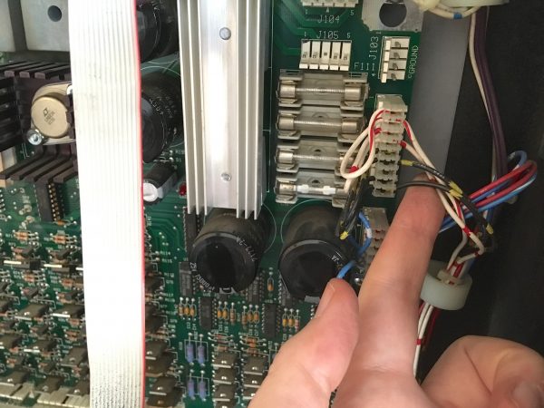
While the service manual makes NO mention of this switch anywhere, it does show connector J102.
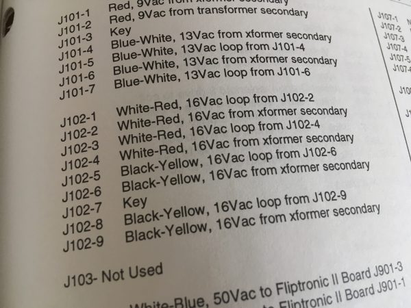
One of the interesting things about this era of pinball machines is that they use a lot of weird power. The newest pinball machines from the likes of Stern and Jersey Jack are actually simpler in this regard, because they use low-power DC LEDs, low power LCD displays, and digital logic for everything except coils. These older machines have 5VDC for TTL logic, 70VDC for coils, three separate high AC voltages for the vacuum fluorescent display, 4VAC for incandescent bulbs, and so on. What I don’t know is what it uses 16VAC for. That’s a bit of a mystery, but for some reason they felt the need to interlock it. Perhaps late in development of the machine someone decided 16VAC was enough to hurt someone, so it ought to be interlocked. The manuals were already being printed, so it was too late to document it? In any case, it appears 16VAC comes from a secondary tap on the transformer, runs up to the Power Driver Board, then runs all the way out to the coin door and back to be interlocked before use by the board. Maybe someday I’ll know the “why” on this one, but I don’t have full schematics for the Williams WPC-S Power Driver Board handy. Figuring that out will have to be a project for another day.
Hi Quinn, Molex part number 63811-1000 is the low-volume tool you want. Not free, but not stupid-expensive either (around $45-55 depending on the supplier). Crimps conductors from 1.4-2.5 mm and insulation from 2.8-4.8 mm. Performs that nice double fold (almost a heart-shape) on the crimp connector … wire will typically break before the crimp connection lets loose.
Regards,
Rick
Speaking of contact/connector failure and old racer tricks, do you have any suggestions for what you’d use for replacing failing connectors in a 50 year old little british sportscar? Previous owner used household twist-type wire connectors. I’ve replaced a few with Deutsch but feel like that may be overkill, and I suspect you know more about this. (What would you use for pinball machines, while I’m at it, if you can’t find the originals? Molex mini-fit jr? Can I put molex stuff on a pachinko machine or will the yakuza come for me?)
They used wire nuts on a car? Oh good heavens. As though British cars don’t have enough electrical problems as it is. 😀 Personally, I’d use something like these:
https://www.delcity.net/store/Weather-Pack-Female-Housing/p_809164.h_809166.r_IF1003?mkwid=s&crid=38094426869&mp_kw=&mp_mt=&gclid=CjwKCAjwv6blBRBzEiwAihbM-caGfw6q7ea8ubUh3TcuvnUrysUhXnUJsm-qDaWC_FFBadQtV3t08xoC7lcQAvD_BwE
Oh, and as for pinball machines, the good news is they still make all the connectors used in newer machines. They haven’t changed much in decades. For older EM machines, they used a type of copper-barrel-on-phenolic connector that can be refurbished or repaired pretty easily.
Well rock on. Thank you very much. Previous owner had lots of ingenuity but not much money. (Hence Harley sidepipes, for instance.) I’m trying to preserve the character while improving the implementation.
I also appreciate the info on pinball machines, for when I get one. Finding documentation on pachinko machines is wretched, and it’d be nice to have actual schematics in English.
I swear, most of my arguments nowadays are between Current Me (lazy, disinterested) and Future Me (lazier, but probably busier, so less disinterested)… my shop supervisor isn’t as committed to quality as yours!
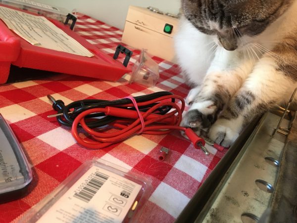
She is committed, although her definition of quality leaves a lot to be desired.
TIL about heat shrink insulated spade connectors. I think I’ve always wrapped them in electrical tape so this is a great tip.
Cool! Glad I could help! 😀