
Testing the limits of my desire to repair.
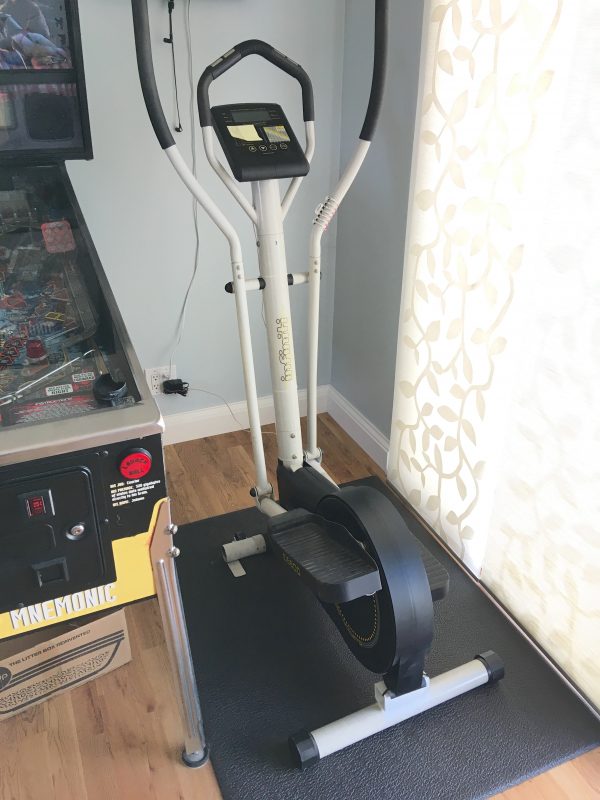
What’s this? Is that my elliptical machine on the operating table again? How can this be? The previous repair seemed quite final. Well, I was doing my daily cheeseburger removal ritual the other day, when the machine suddenly developed a distinct starboard list.
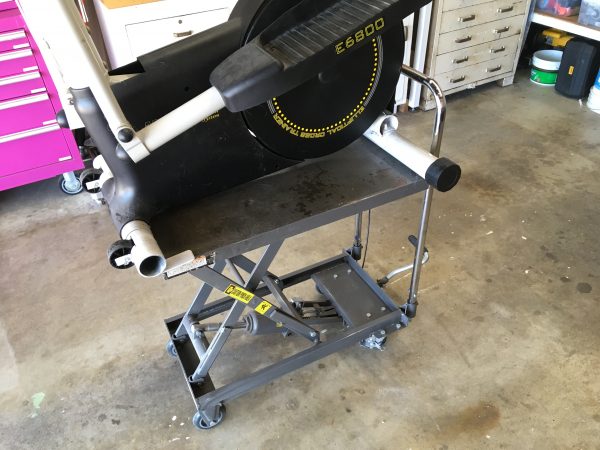
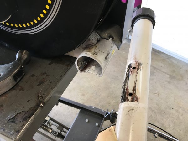
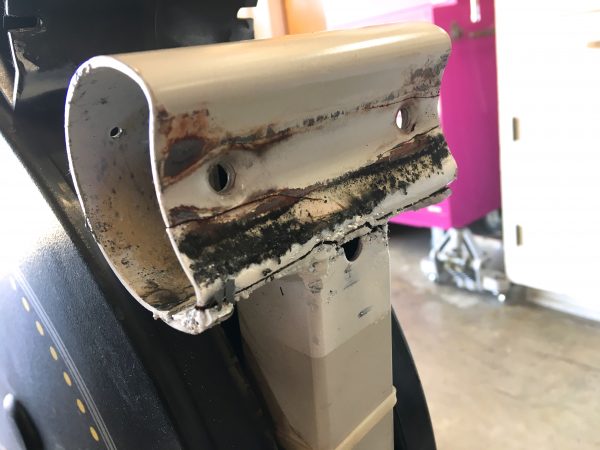
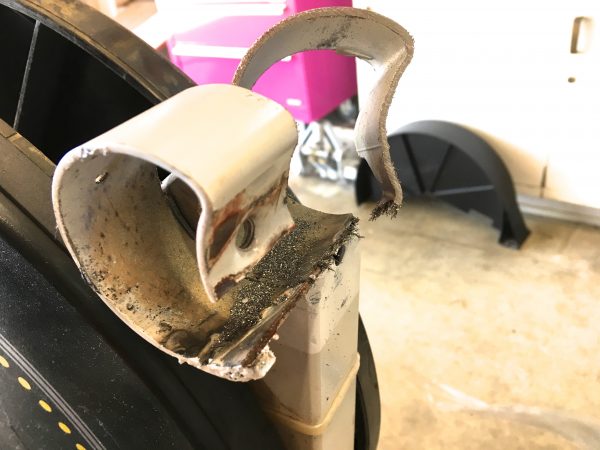
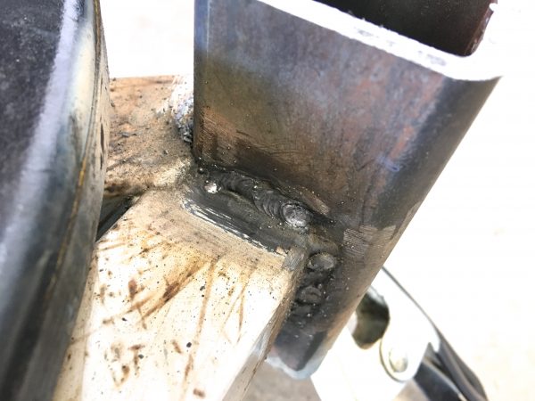
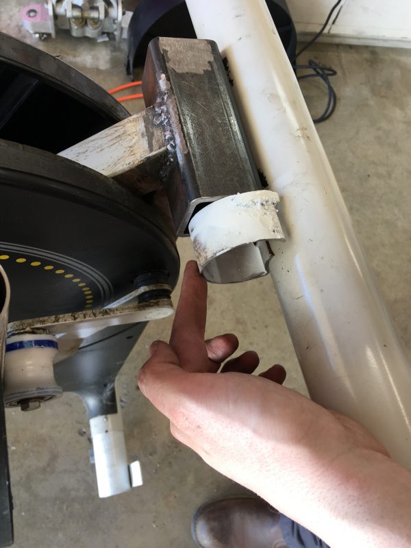
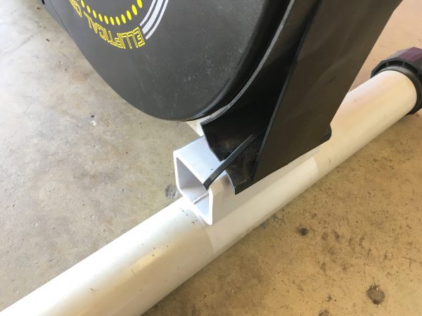
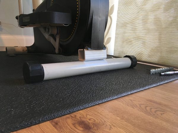
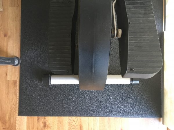
If you look under the rear of the machine, you’ll see the long rear “foot” is attached with a shorter section of tubing that is squished on the bottom. I’m calling that “squished” piece the “rear subframe”. It joins the main frame of the machine to the rear foot piece. Well, let’s take a closer look at that subframe. I’ve repaired that part before, when it developed a crack. I figured perhaps my weld let go (I’m a lousy weldor).
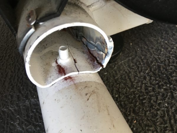
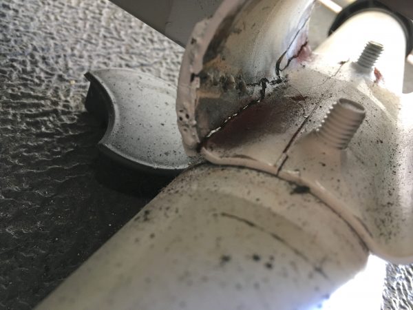
Not all show up in the photo, but counting all the hairline fractures I see, there appear to be nine cracks in this part! Amazing it’s still in one piece at all! I’m fascinated by mechanical failure, and this is a great example of it. While using the machine, your weight naturally shifts back and forth, creating constantly moving stresses inside the steel. It’s amazing how this can manifest (over the course of years) into such catastrophic failure.
Well, it was immediately clear that no mere patch job was going to get it done this time. That whole part needs to go. Unfortunately, that part is welded to the main frame of the bike, so this repair won’t be a walk in the park.
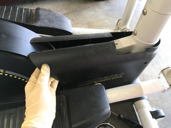
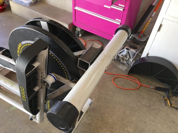
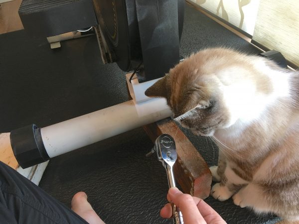
First things first, we need some access to it. Let’s see how close we can get.
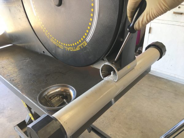
Of course, nothing is that easy- the front edge of the dust cover disappears under two other plastic panels on the front.
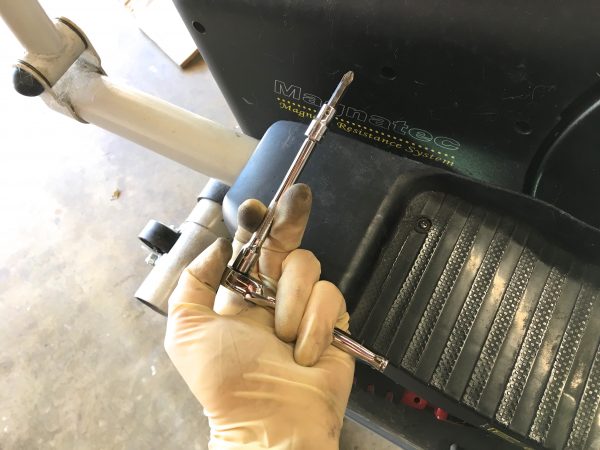
Some of the screws holding those front panels on were insanely tight. Clearly installed with extreme prejudice via some demonic pneumatic tool on the assembly line. Not stripping them upon removal will be a challenge.
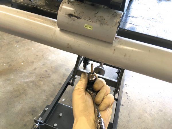
With all the plastic covers out of the way, we can turn our attention to the large foot at the back. It attaches to the subframe with some dome-head bolts.
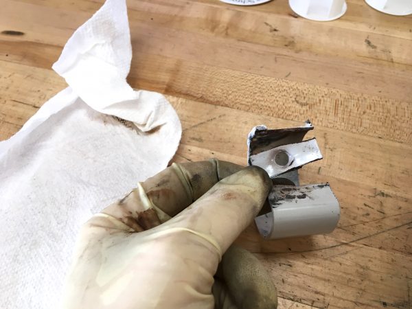
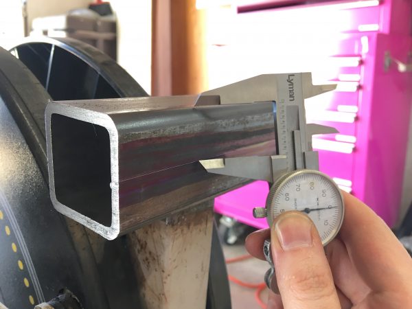
With all the pieces apart, we can see some interesting differences. The foot is fairly heavy wall tubing, but the subframe is about half as thick. Amazingly, the main frame (to which the subframe is welded) is even thinner. It’s like tissue paper. It’s some sort of monomolecular graphene form of steel that probably should win a Nobel Prize for manufacturing efficiency. Luckily the main frame is showing no signs of wear, and the foot is perfectly well made, so it’s also fine. It seems the subframe is the only place where they cut the specs a little too close to the line.
In case you’re wondering, the subframe tube is supposed to have that squished shape. It’s a cheap way to join two pieces of tubing together in a way that is better supported. Two cylinders only touch on a single line, so there would be a lot more stress on the areas around the bolts if one tube wasn’t squished like this. They can also get away with thinner material by employing this shape.
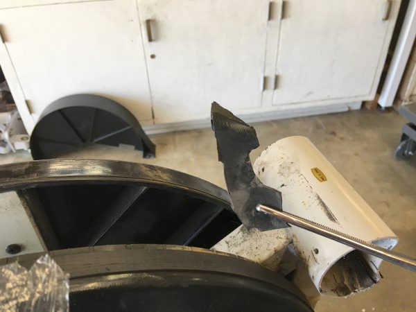
Now we get into the meat of this repair, though. The subframe is welded to the frame, so we gotta cut it out of there. I decided to start by carving off the drumsticks with the portable bandsaw. This will give me much better access to the main welds.
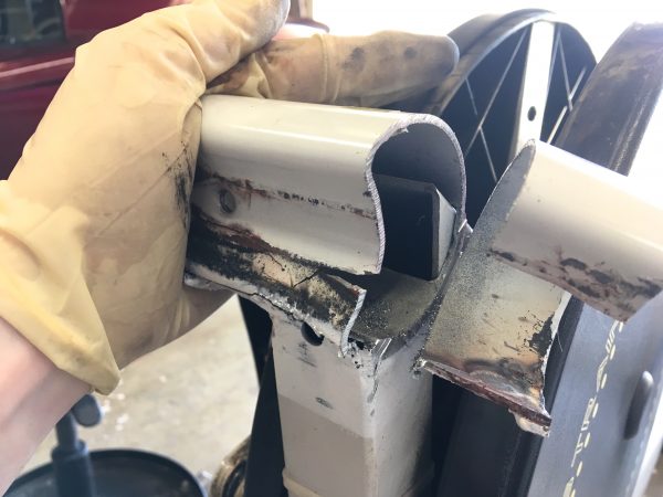
With the big chunks out of the way, we now need to separate it from the main frame, which means cutting those welds somehow. I could access some of the welds with the angle grinder. I keep small mostly worn-out zip discs around for jobs like this, when you need to get in tight. I couldn’t get in all the way though, and I really wanted to avoid disturbing the factory welds of the two main square tubes to each other. The factory welds are better than my farmer-weld replacements would be.
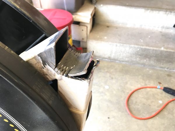
With the chunks free, I was able to clean up the area in preparation for welding in a new part. I ended up with a hole that was a different shape than what the original part fit into, but we can work with that.
I also took time to remove anything nearby that might be damaged by the welding. There were electrical somethings zip-tied to the tubing inside the machine, which I could reach with a large forceps. One of the many advantages of growing up with a family full of veterinarians is that I learned the shop value of surgical tools. If you don’t own a full range of forceps, drop what you’re doing and buy some right now.
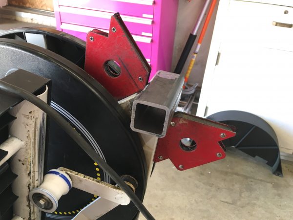
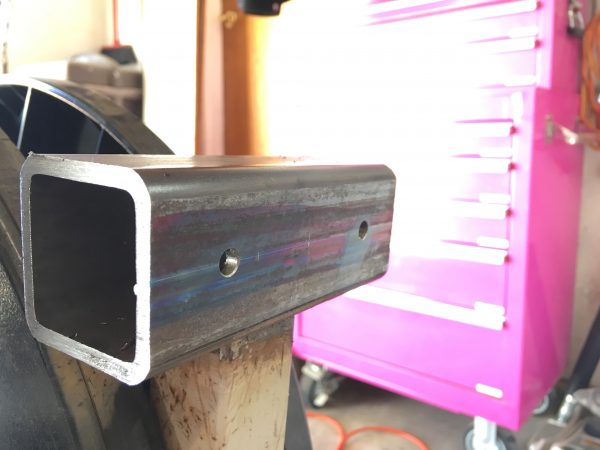
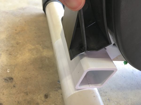
Now I needed to figure out what to replace that subframe with. At first I tried some round tubing. I have some really heavy wall stuff left over from the front foot repair, and it’s a decent match diameter-wise for the factory part. I tried to squish it the same way the factory part was by heating it to plastic temperature along one edge, and pressing a round part down into it. At least, that was the plan. Even with the acetylene torch, however, I couldn’t get enough heat into it. Tubing has a lot of surface area, and it reached an air-cooling equilibrium that was too low. After burning through a lot of torch fuel, I decided a forge would be needed for this idea. In any case, because the opening I made in removing the old part is not round, a round replacement part wasn’t a good match. After fooling around with some scraps from the junk pile, I found that a piece of 2″ heavy-wall square tubing was actually a really good fit for the opening in the frame. It would mean the joint to the foot was flat-surface-on-cylinder, which is again a single line. However, all this means is that the bolt areas around the foot will be a bit more stressed, and the foot is easy to remove and repair/replace if needed. The new subframe would be so beefy that it will definitely not fail due to this interface. I now had a plan!
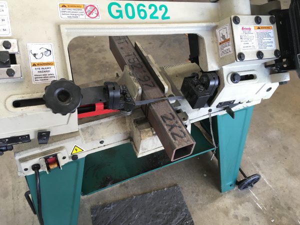
Tubing this heavy shrugs off the portable bandsaw with the shrill cry of a thousand banshees, so I had to bust out the horizontal bandsaw. I maintain these crappy import horizontal bandsaws are a good bargain once you tune them and put a proper blade on them. It doesn’t break a sweat on this heavy tubing.
With the tubing cut, it was time to see what I could do about fitting it up.
The next task was to get the welder set up for this job. It was going to be tricky, because I’m welding very heavy-wall tubing to very thin wall stuff. The settings to get really good penetration on the square tubing would blow through the thin-wall stuff like a twister through a trailer park.
I opted to set the welder up for the low side of what the thick stuff wants (just enough to get decent penetration), and focus on heat control. My plan was to basically lay the bead on the heavy stuff, while just sorta “washing” the weld puddle up on to the thin stuff as I go. I figured I had better practice this first.
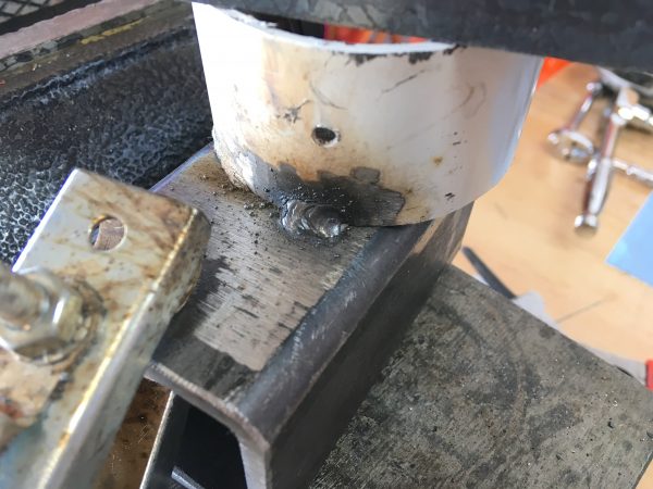
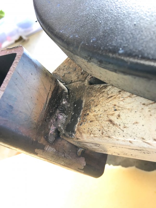
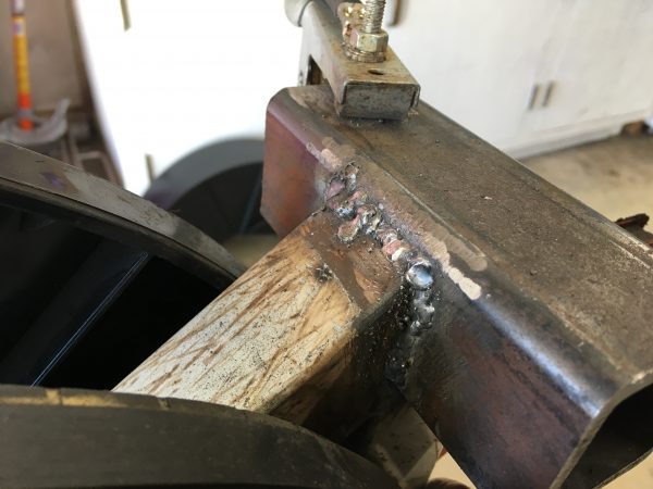
Okay, so the welder is now set up right, but getting the weldor set up right is a different can of worms. Unfortunately, all the actual welds are in tricky places. None are flat, and access is not good anywhere. By rolling the exercise machine around on the floor, I was able to avoid any upside-down welding, but I did have to do some vertical. Keeping away from the plastic parts really limited where I could get good angles, but I did the best I could.
Results were mixed. Some of the beads turned out sorta okay, and others are complete rubbish, but they did all achieve good penetration. I’m confident they will hold, but they will not win any beauty contests.
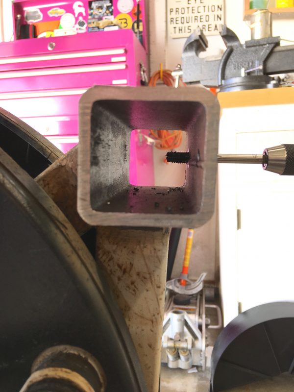
Next we need to find a way to mount the foot to our new subframe. The easiest thing seemed to be to re-use the old mounting bolts. On the factory subframe, they used that technique where the holes are punched, and then the flashing left behind from that is threaded to take the bolt. This is a very inexpensive way to thread a fastener into thin-wall material. In my replacement, however, the material itself is thick enough to take threads, so I can simply drill and tap it directly.
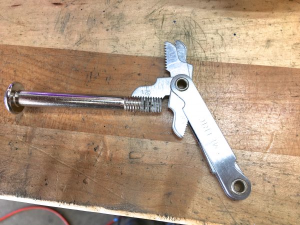
The next step was to figure out what the factory hardware is. Since it was made overseas and it isn’t 1978, you can bet it will be metric. I grabbed that thread gauge first.
It was at this point that I realized I should have made these holes before welding the part in place. This would have been way easier to do on the drill press. That’s what I get for not actually having a plan. Instead, I had to drill them by hand and do my best to get them straight.
Now for a quick test fit of the bolts…
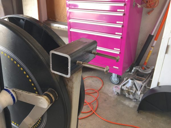
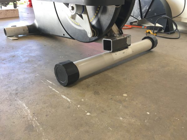
Okay, moment of truth! Let’s do a test fit and see how she goes.
There’s one little detail to be aware of here. The overall height of the back of the machine was being established by the thickness of that factory “squished tube” subframe. My new part isn’t exactly the same cross-section, when measuring mating-surface to mating-surface between the foot and the main frame. However, I think it will be close enough that you can’t feel it on the machine.
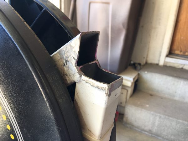
Okay, let’s get this thing back on its feet and see if it’s going to work.
Now for some paint, and reassembly!
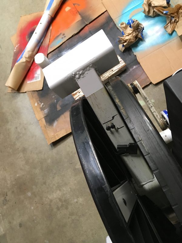
I’ve used that same white spray paint for all my repairs on this machine, and of course it doesn’t match the almond factory color. I like that you can see the history of all my repairs at a glance. It’s like software source control, but for madness.
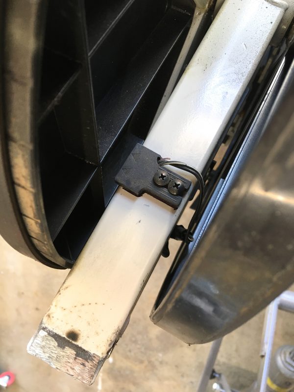
“But wait,” you might be thinking, “What about the rear of the dust cover that bolted to the round subframe part?”. If you thought that, you’re a lot smarter than me, because that didn’t occur to me until the moment I tried to reinstall it.
The mounting bolts for that plastic part are required to be at a funny angle, which was fine when the tubing was round. On this square stuff, not so much. I took a shot at drilling and tapping angled holes in the square tubing, but the angle was impossible to do. There was no way to get that drill started.
Need to attach something weird to something else weird with no fasteners? Zip ties.
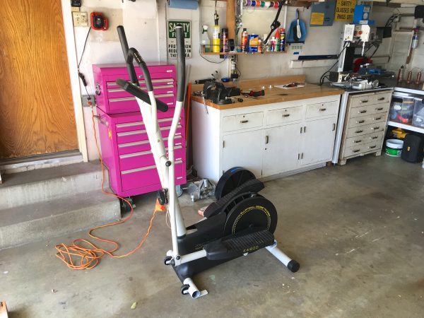
Feeling pretty chuffed with myself, it was time to put the machine back in its spot.
Even sitting on the rubber mat, the machine had a distinct front-left-to-rear-right rock to it. Luckily, an easy fix was at hand. I just needed to shim one side of the rear foot down a bit with a washer on one of the mounting bolts.
Oh, and, in case you were wondering, those crooked bolts did show themselves in the end.
After all that, is the machine actually fixed? In a word and three letters, “OMG yes”. I didn’t realize until now how wobbly that machine really was. I was used to it, and the stress fractures in that part have formed gradually over time. The whole machine was jello, but I was accustomed to the feel of it. Now, it feels completely rock solid, like standing on, well, rocks. The whole machine is amazingly quiet and smooth now as well. Not nearly the squeaky rattle trap it usually is. Who’d have thought that the rigidity of the frame could make such a difference in how the entire machine functions. I always learn something in these repairs, and this time I gained a whole new appreciation for how steel structures live, breath, and ultimately fail.
What’s next for this machine, you might wonder? Honestly, the next most likely failure point is the main frame, around where I welded in the new part. That’s the next potential weak link in that chain. When that fails, it’s highly likely to be not worth trying to repair. I’d pretty much have to rebuild the whole machine from scratch to fix that. Surely that would be a bridge too far to keep this thing going? I should know by now never to make statements like that around here.
For removing screws, I came across this in a Mustie1 video:
https://www.eastwood.com/eastwood-screw-buster.html
THIS.
That looks like quite a beast!
In the absence of magical air tools, I always wonder whether it’s possible to get a similar effect by just applying some load to the ratchet and tappy tapping the back of it with a hammer
I would definitely not hammer on a ratchet- they are a delicate mechanism by comparison. However, a technique people do use is to tap on the back of the screwdriver. The direction of the vibration doesn’t matter as much- getting any impacts into the fastener is generally enough to break the stiction. This is how cheap “switchable” hammer drills work. They hammer inward rather than rotationally like a proper pneumatic impact gun does.
You can *kindof* get this effect by hammering on the back of a screwdriver while trying to turn it, but it’s not the same.
If you lack air tools, a hand impact driver works okay.
https://www.amazon.com/TEKTON-2905-8-Inch-Manual-7-Piece/dp/B000NPPATS/
I can’t tell if Sisyphus or Theseus can lay more claim to this machine.
ROFL Okay, you win the internet today. Best comment ever.
TIL the word “weldor”. Sounds like it could be a welding-themed cartoon evil genius (which I guess is… the tiniest bit apt?)
English pendants love to drop that word and claim that “-or” is a person who does something, and “-er” is a thing that does something. Anyone who claims rules like that is lying though, because all of English is exceptions. We have “actor”, “donor”, and “evaluator” (all people), but we also have “singer”, “painter”, and “baker” (also people). Then other words do both, like “driver” is both a person and a thing that drives (cars and golf balls, respectively). Anyways “weldor” is a nifty word that I enjoy using, but “welder” is perfectly fine and is clearly replacing the former in common usage. Language evolves.
These days we talk casually about ball peen hammers, and rarely about ball pein hammers. 70 years ago it was ball pein hammers with some ball pean hammers. 150 years ago it was ball pean hammers with a few ball pene hammers. (This from my sampling of old blacksmith manuals.)
That piece of square tubing is amazing. It should outlast our civilization.
When I see plastic tubing ends intended as feet, that have multiple flat sides on them, I always hope they are set up as an octagon/decagon with an off-center boss that fits in the tubing, so I can adjust the foot height by twisting the plastic thing until the right offset is established. This is how the feet on my tablesaw offcut table work, to adjust for non-level floors. Presumably not the case with yours, though, alas. I liked the idea enough that I’ve 3d printed some for home projects.
Now, you’ve convinced me to buy some magnetic trays.
Yah, honestly, I think those eccentric plastic bits are probably supposed to be leveling feet, but they don’t work at all. They immediately collapse to their lowest point no matter what I do. As far as I know they have never worked for their intended purpose.
I think, after all these years, your loyal elliptical finally deserves its own menu header.
(I’m also curious if the long-lost designers of this unit, or the company that made it, have been following your repairs and have any personal insights. Shocked that their all-in-a-day’s-work design has inspired such a years-long dedication? Taking bets on what would fail next? Mumbling that such-and-such should have failed years ago? Proudly crowing on LinkedIn that they had a hand in making something “now famous on the internet!”)
Hahaha, nice to know someone actually looks at those headers. I’ve often wondered if they have any value. Adding a new one will push it to two lines in most browsers though, which looks pretty ugly. There are a couple of things I wouldn’t mind adding there though.
I look forward to the day that the consumerist in you decides it’s time for a new exercise equipment, but the mad hacker in you takes over, and we get Furiosa’s Elliptical Machine or something like that.
Just a gnarly steel over built and engineered piece of equipment, that will be on display in a museum in the distant future when the next dominant species takes over the planet.
Haha, well, if I end up welding a whole new frame for this thing, it’ll definitely be Furiosa’s Elliptical then. 😀
Has working on this machine over the years given you thoughts as to how you would approach building an elliptical from scratch?
That’s a great question! I’ve learned a lot about how consumer-grade machines like this are built. I think I see which corners are cut for costs, and those are the areas I would improve. Things like material thickness, bearings, rollers, etc.