This is what happens when there’s nothing on TV.
I’ve been listening to a really great podcast lately called No Quarter. It’s all about remembering and reliving classic arcade games, of the sort us folks-of-a-certain-age grew up with. If you’ve never played Dig Dug or Space Invaders in a smoke-filled, dimly-lit room with purple carpet, blacklights, and a creepy dude shifting pot in the corner, then you don’t know what I’m talking about. Also, get off my lawn.
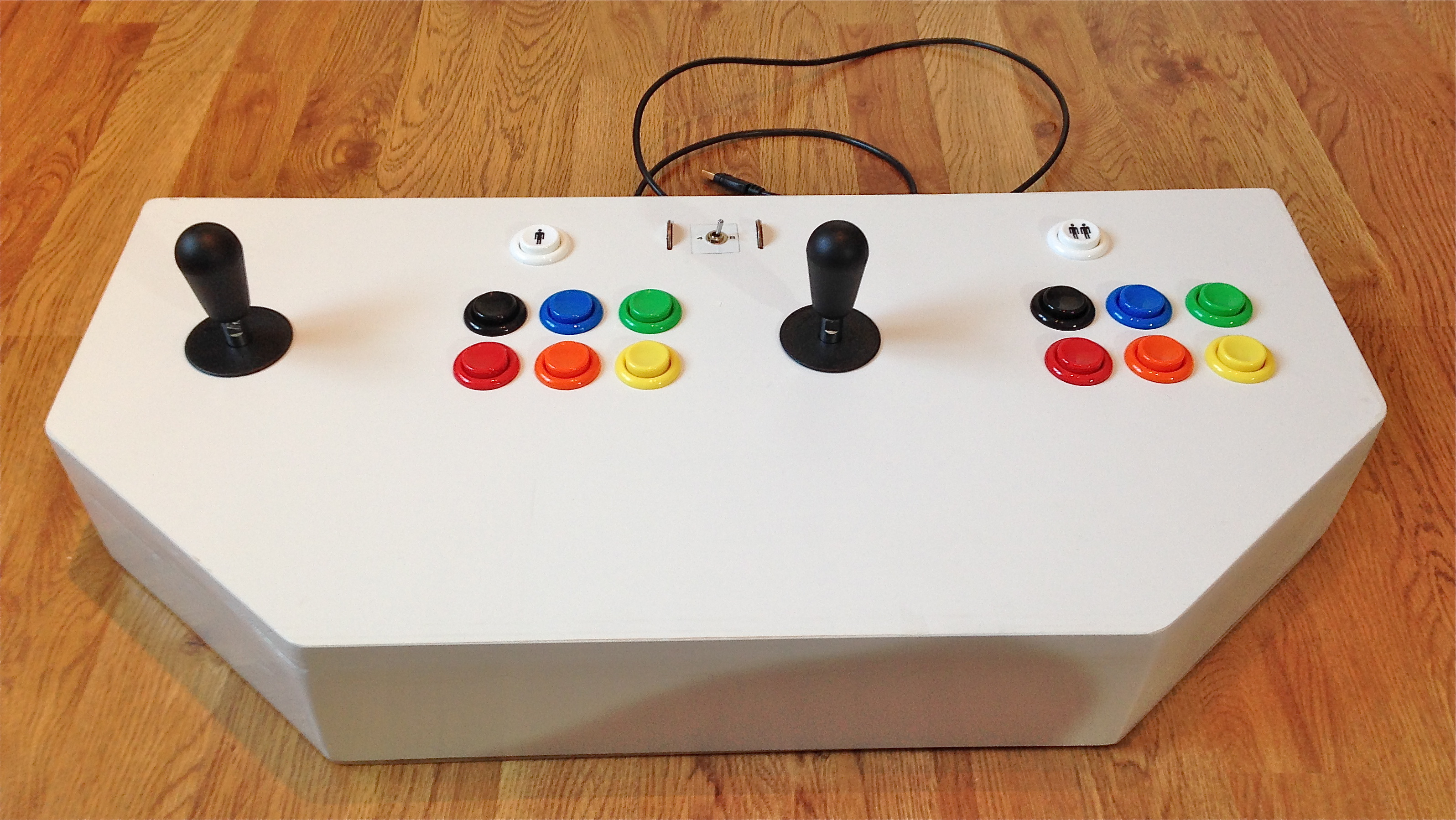
The boys at No Quarter have rekindled my love of those games, but to play them properly you need the right equipment. Rather like a samurai making her own sword, this is something of a rite of passage for people who want to play these old games The Right Way™. Namely, building a control panel. I wanted something clean, fairly compact, but beefy enough to play most games from 1970 up through about 1993. Here’s what I came up with.
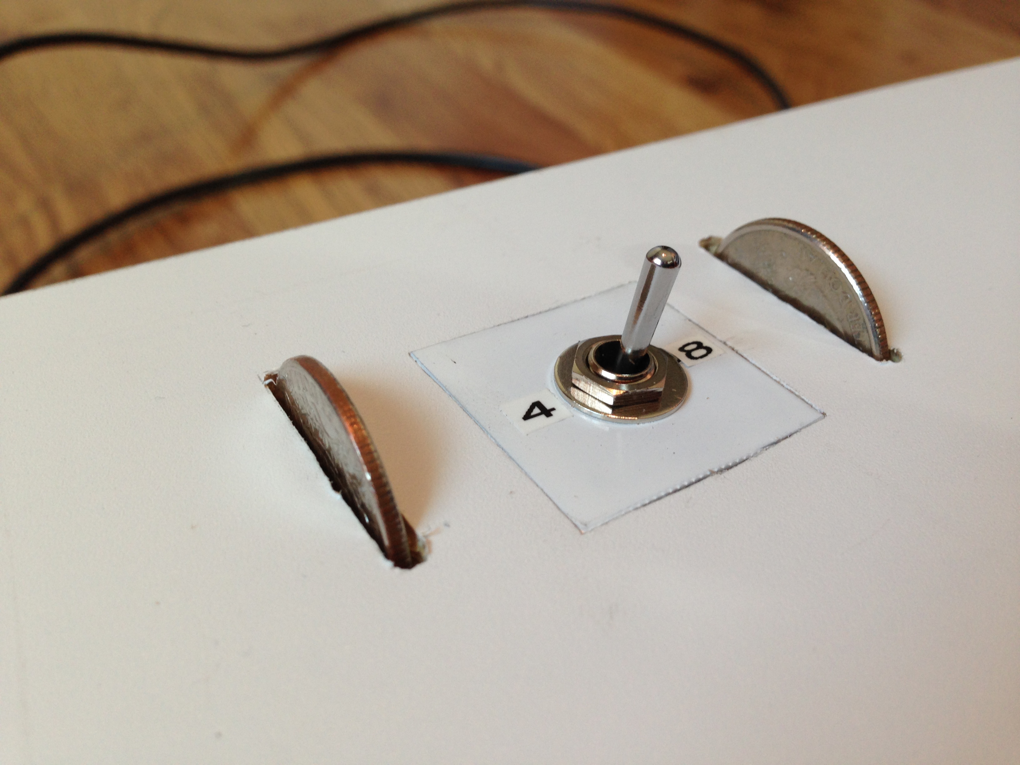
Here’s a close up of two of the signature features: servo-powered joystick mode selection, and coin slots:
Here’s a demonstration of the coin buttons:
I went with a simple all-white design, because it will match the decor in the room it will be going into. No crazy airbrushing of Teenage Mutant Ninja Turtles driving the car from Pole Position here. I did a ton of research over at the Build Your Own Arcade Forum. I’d also like to thank the You Don’t Know Flack podcast for being very informative, and of course Slag Coin, arguably the best single resource there is on this topic.
The first step in designing one of these is figuring out which games you want to play. This makes ALL the difference in terms of what types of controls you buy, how big the panel is, what type of electronics you need, and so on. As mentioned, I’m interested in most of the range of arcade games from the 1970s into the early 1990s. However, I’m willing to forego trackballs, spinners, flight sticks, and other exotic input devices. Yes, I know I’m giving up Centipede and Tempest with this design, but I’m okay with that for now. I want to play multiplayer games, but two people is fine- I don’t need four. With that criteria, the only special gear I needed was switchable 4-way/8-way joysticks. No, you really can’t play 4-way games with an 8-way stick. The extra inputs will confuse older games, and watch how fast you die in Ms. Pac Man with an 8-way stick. Trust me on this.
There’s two main choices for sticks- Happ and Sanwa. The former are American, and probably what you played on if you came up in American or Canadian arcades. However, the only switchable 4-way/8-way Happ stick requires dismantling the mechanism to make the change. Furthermore, the conversion only changes the stick electrically. Physically, it still moves to 8 positions in 4-way mode. That’s not good enough for my taste. I wanted something switchable from the top of the panel, something that would feel authentic in both modes, and something easy enough for guests to use.
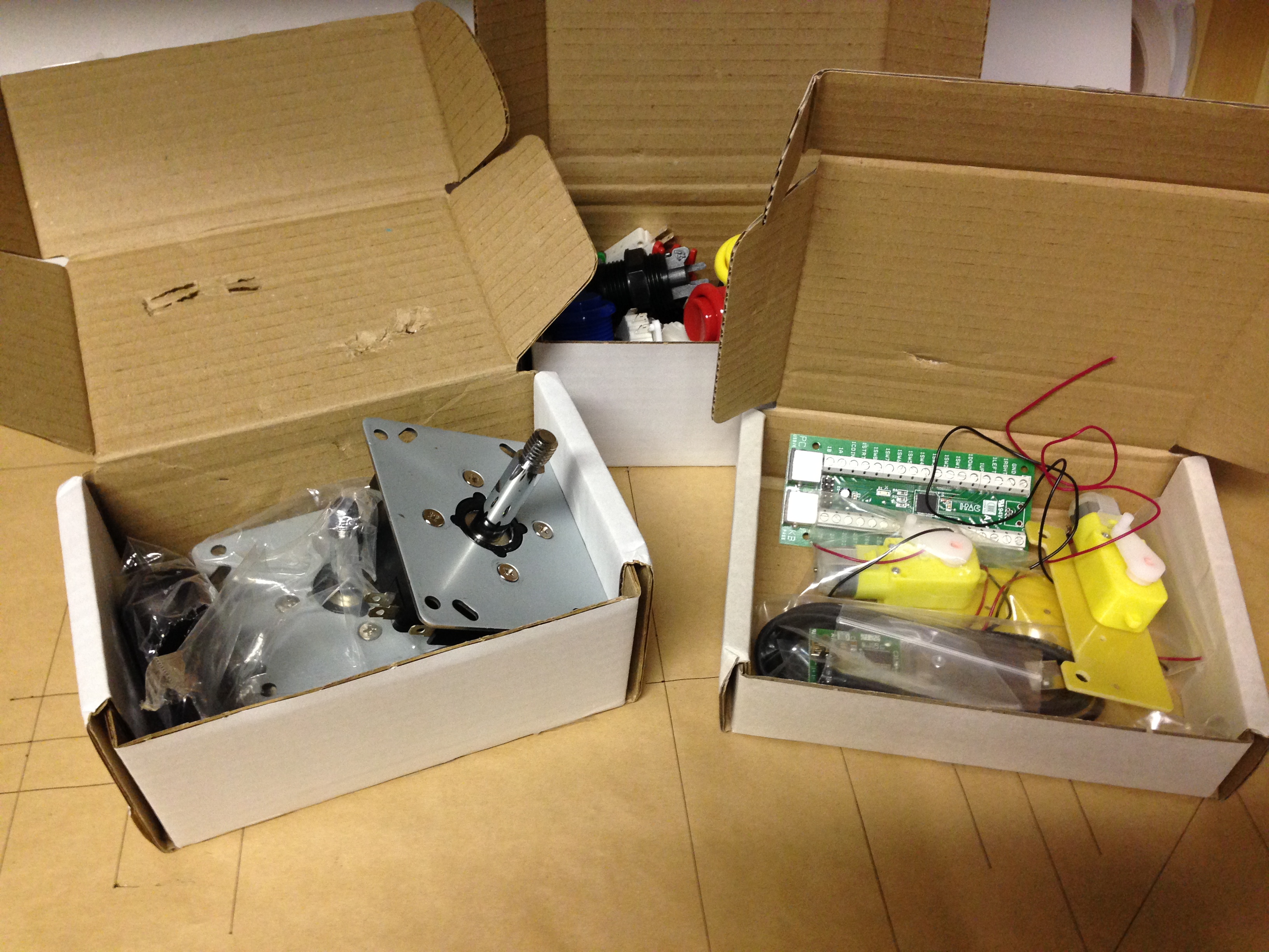
The magic bullet came in the form of the Ultimarc Servo Stik. They take Sanwa sticks, and convert them to be switchable with a servo motor. The switch is done with a restrictor plate, so the physical motion of the stick actually changes. It feels different as well as being electrically different in each mode. It’s really awesome, and I could not be happier with these.
For buttons, I went with Happ, as they have the right North American arcade look and feel. The last thing needed is an encoder, which is a circuit board that converts the arcade control inputs into USB keyboard inputs for use by games. Ultimarc to the rescue again, with the really excellent iPac 2. Ultimarc also carries real Happ buttons (not knock-offs, like you’ll find on eBay and elsewhere). So, it was easy to place one big order from Ultimarc, and get everything I needed. Even though they’re in the UK, they ship DHL, and the stuff was at my door in the US in two days.
With parts in hand, it was time to lay out the panel itself. The outer dimensions are based on the Mortal Kombat 2 panel (available here). The button spacing is taken from X-Men Vs Street Fighter 2 (in the service manual, available here). Other dimensions, such as joystick spacing and wrist area, were taken from the X-Arcade stick. I’m not going to link to that, because those guys were unpleasant to me when I tried to inquire about buying something.
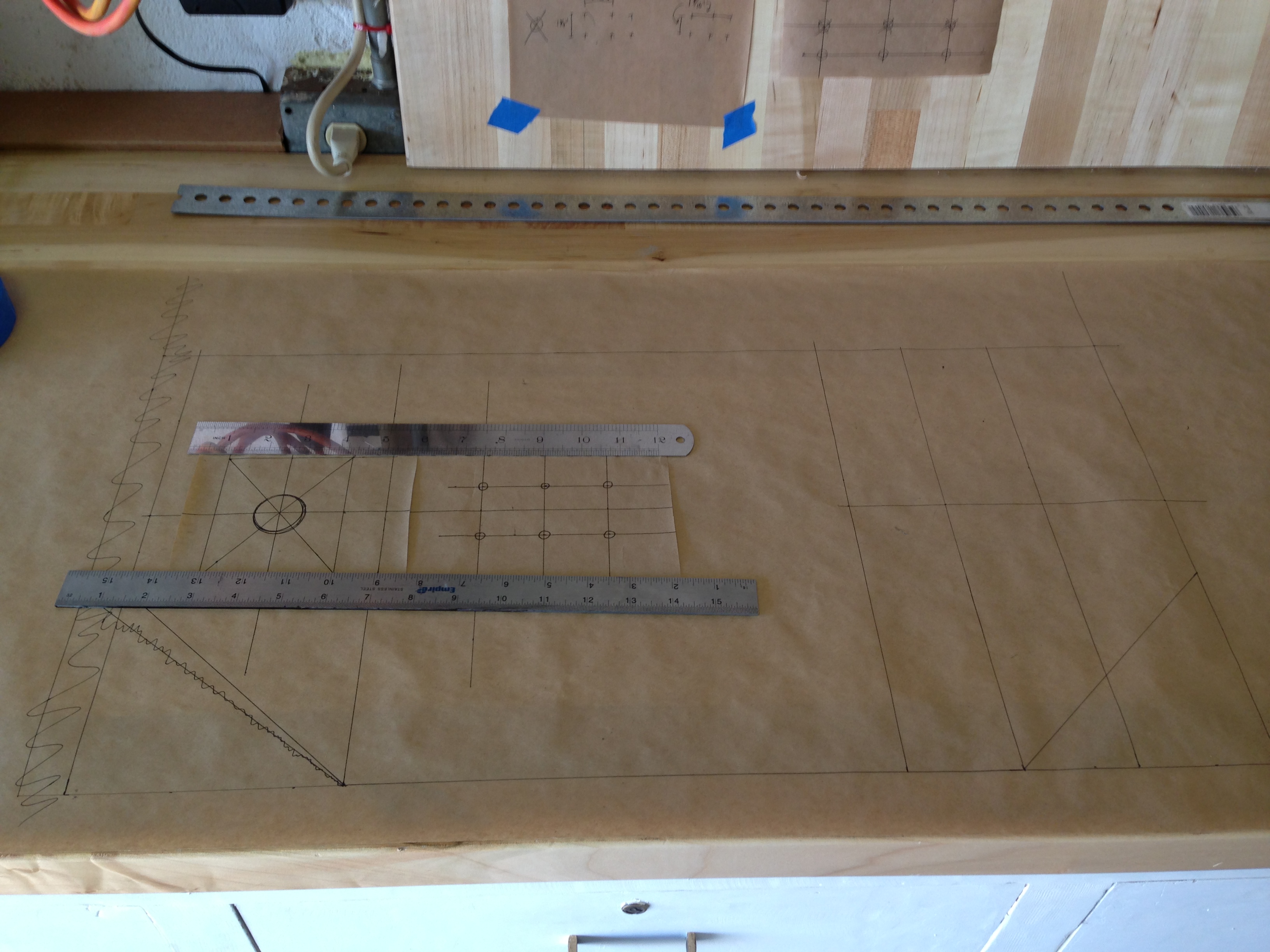
Having an actual-size template on paper is very useful. For example, when it comes time to drill, you can line up the template on the piece, and stick a pin through the right places on the diagram to mark the holes for drilling in the material below.
For material, I opted for 3/4″ melamine. This is plywood with a plastic coating on two sides. It’s mainly used for making the insides of kitchen cabinets. It’s nice looking, feels smooth, and can be cleaned easily. Also, the previous owner of my house left a bunch of it behind. That’s the main reason I used it, if we’re being honest. You can’t argue with free. Honestly, the melamine was somewhat of a pain in the ass to work with, so I’d probably just use high quality plywood next time.
After cutting out the top piece, the first challenge was mounting the joysticks. Because the Servo Stiks are based on Sanwas, they are intended to be mounted in a Japanese-style metal control panel, rather than an American-style wood one. That means they need a fairly thin surface above them. Slag Coin has a huge section on all the ways around this. Joystick mounting (particularly under-mounting, to hide the screws) is an art and science beyond the scope of this article. I’ll show you what I did, and I can say it worked great. You could lash your horse to these sticks, and he’d still be there in the morning (though he may have beaten your Moon Patrol score by then).
I carefully measured and marked the areas that would be occupied by the joysticks underneath, then routed the area down to 1/4″ thickness. Next, and I marked, drilled for, and installed “insert nuts”, which are brass fittings that give you secure machine-screw threads in wood. They are also much stronger than wood screws put straight into wood. This is important for joysticks, which will take a ton of abuse.
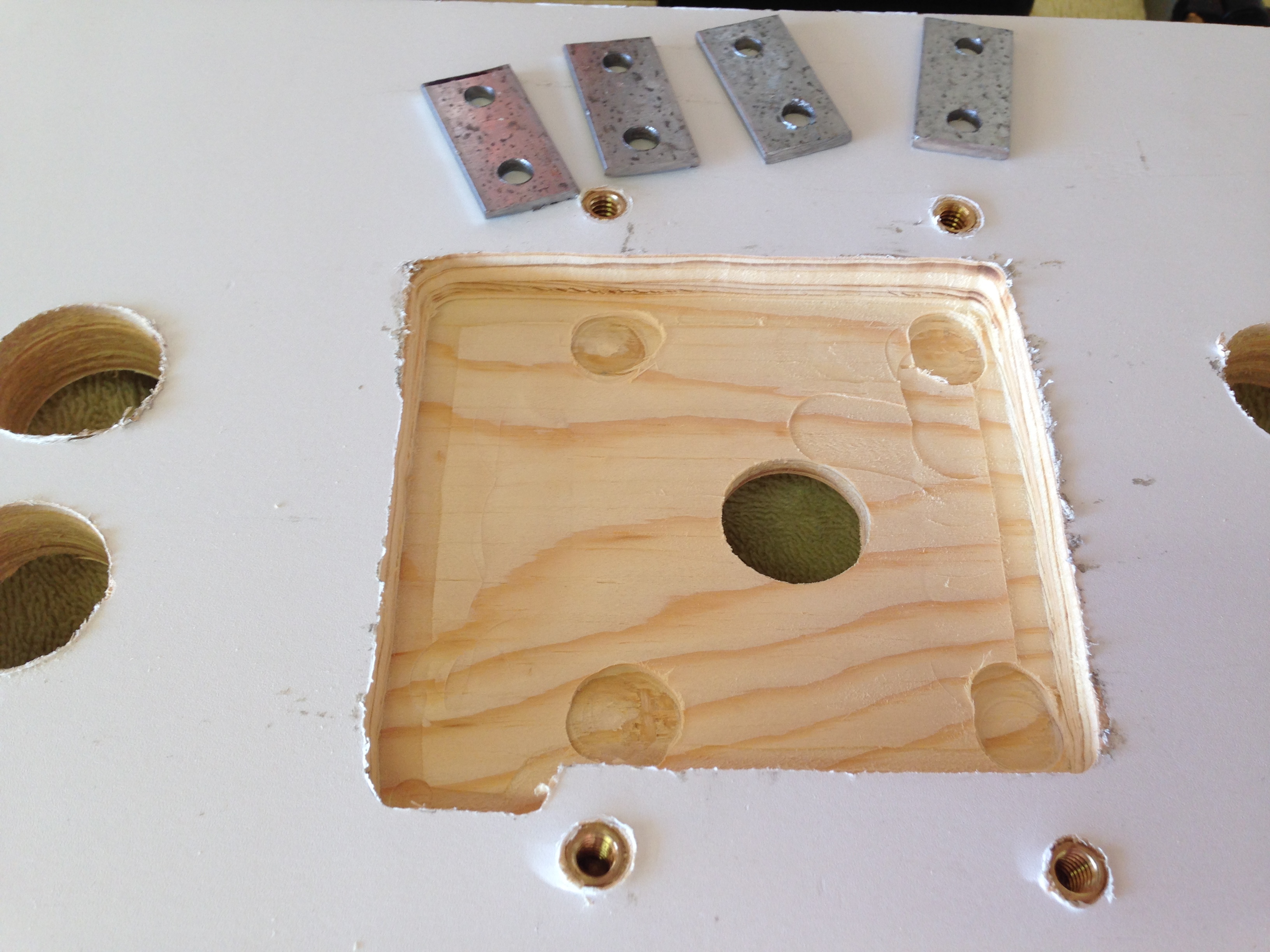
The sticks are mounted using a technique called toe clamping. Don’t google that, trust me. Here’s what it looks like.
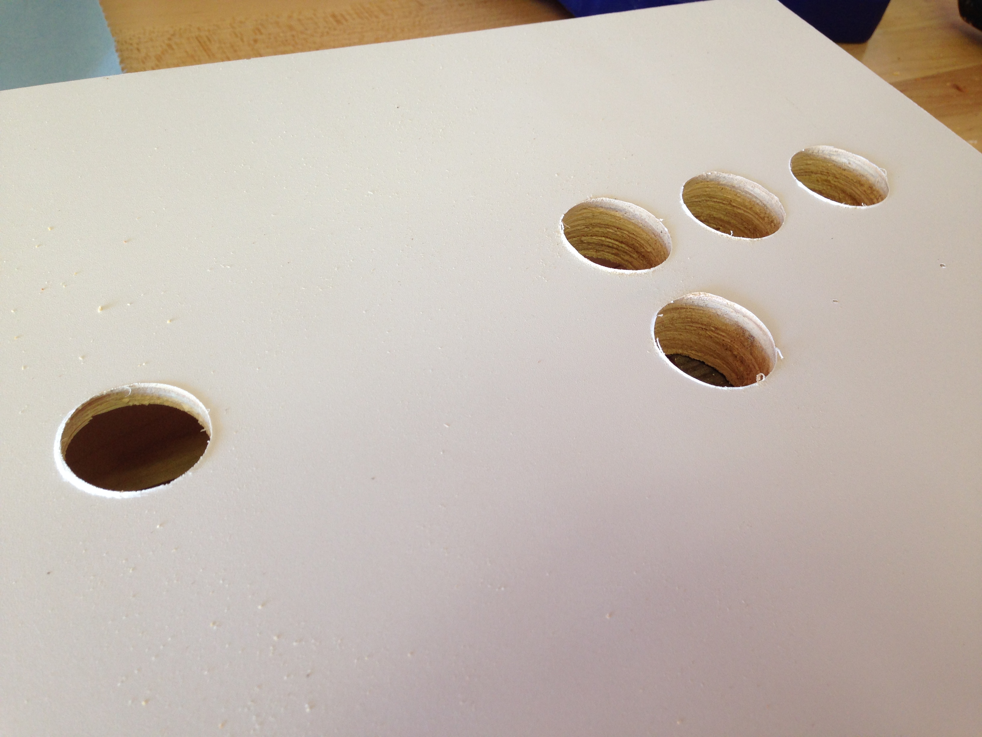
Next it was time to drill for the buttons.
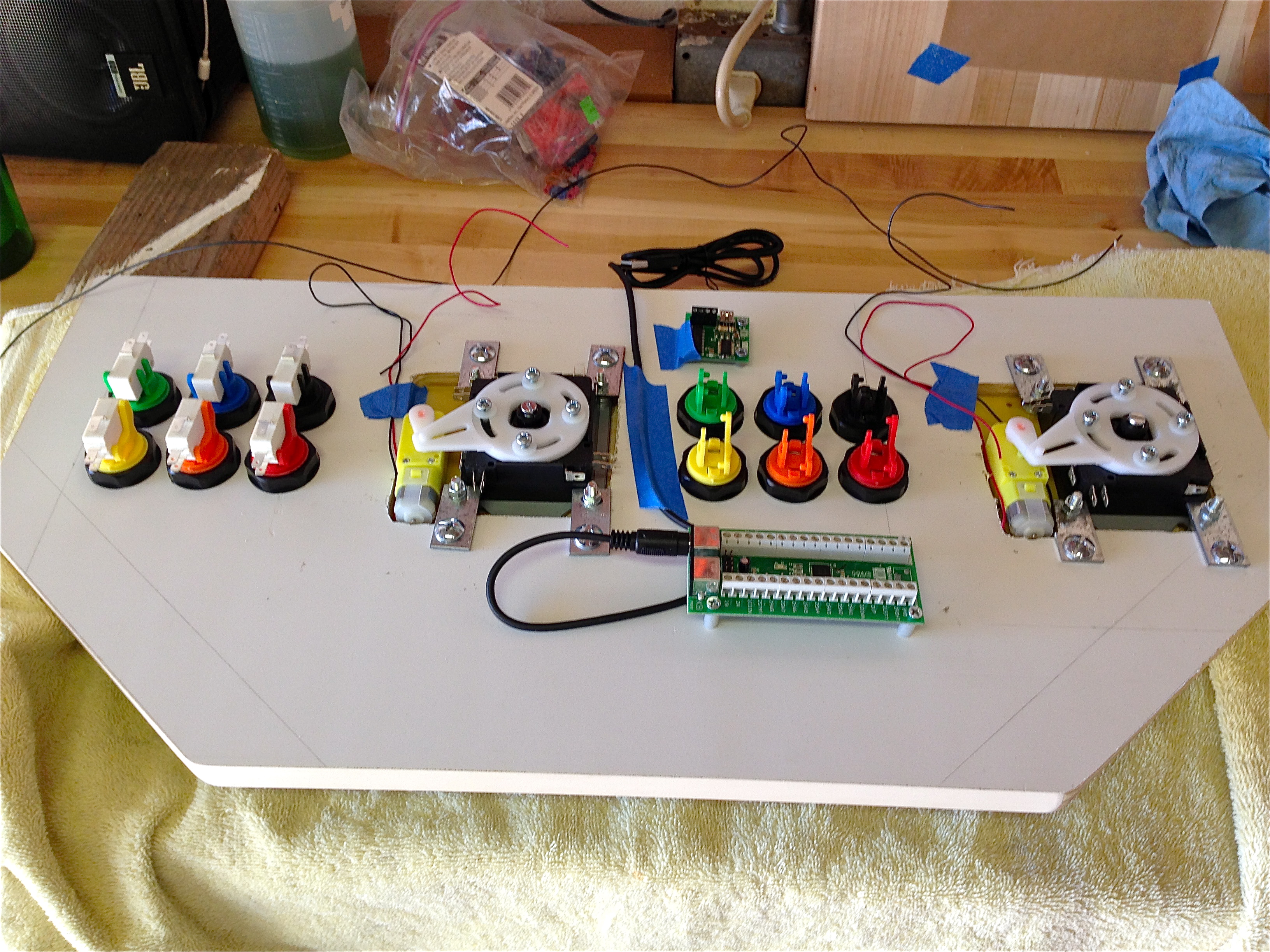
Next I planned the electrical layout. Tidy wiring is all about planning, so I did my best to make sure this would all work ahead of time.
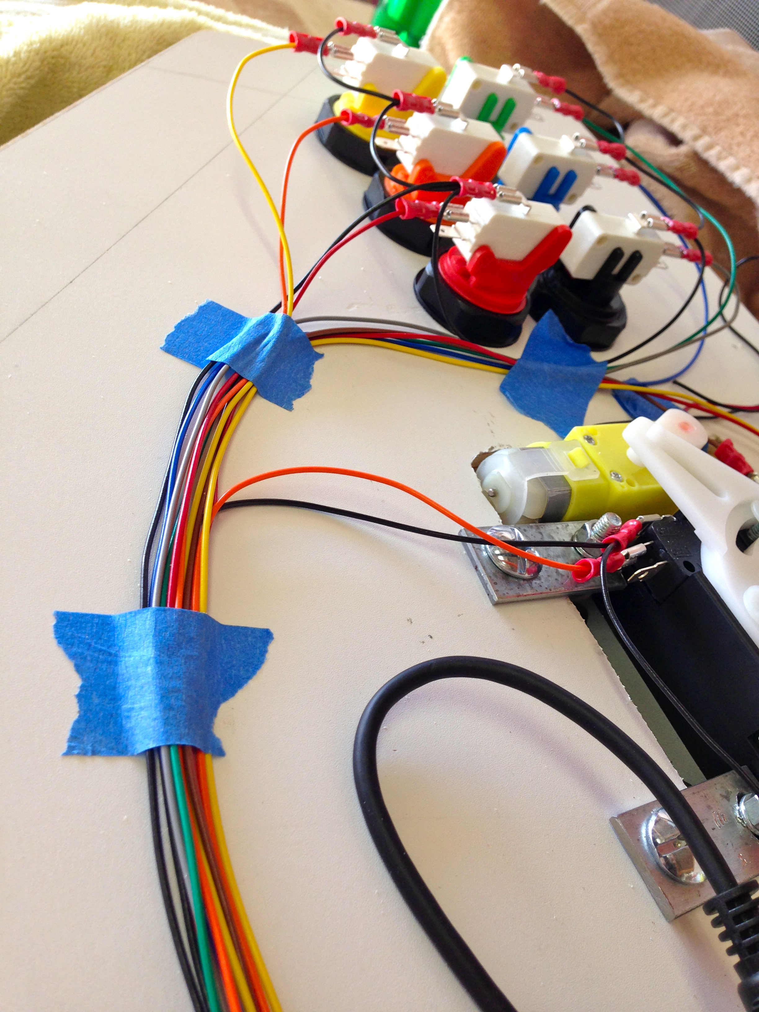
It’s very helpful to have a lot of different colors of wire for a job like this, and in this case we need stranded 22 AWG. 22 AWG is way overkill current-wise, but arcade controls use 0.187″ blade crimp connectors, and 22 AWG is the smallest you can use in those. It turns out that getting a bunch of colors of stranded 22 AWG wire isn’t that easy. I ended up finding some multi-conductor shielded cable at my local surplus shop (All Electronics, who also sells it online). Give All Electronics your business. They are awesome dudes, and real hackers running a proper surplus shop of the sort that you don’t often see anymore. This multi-conductor cable can, with some effort, be dismantled into 10 colors of 22 AWG stranded wire. Perfect!
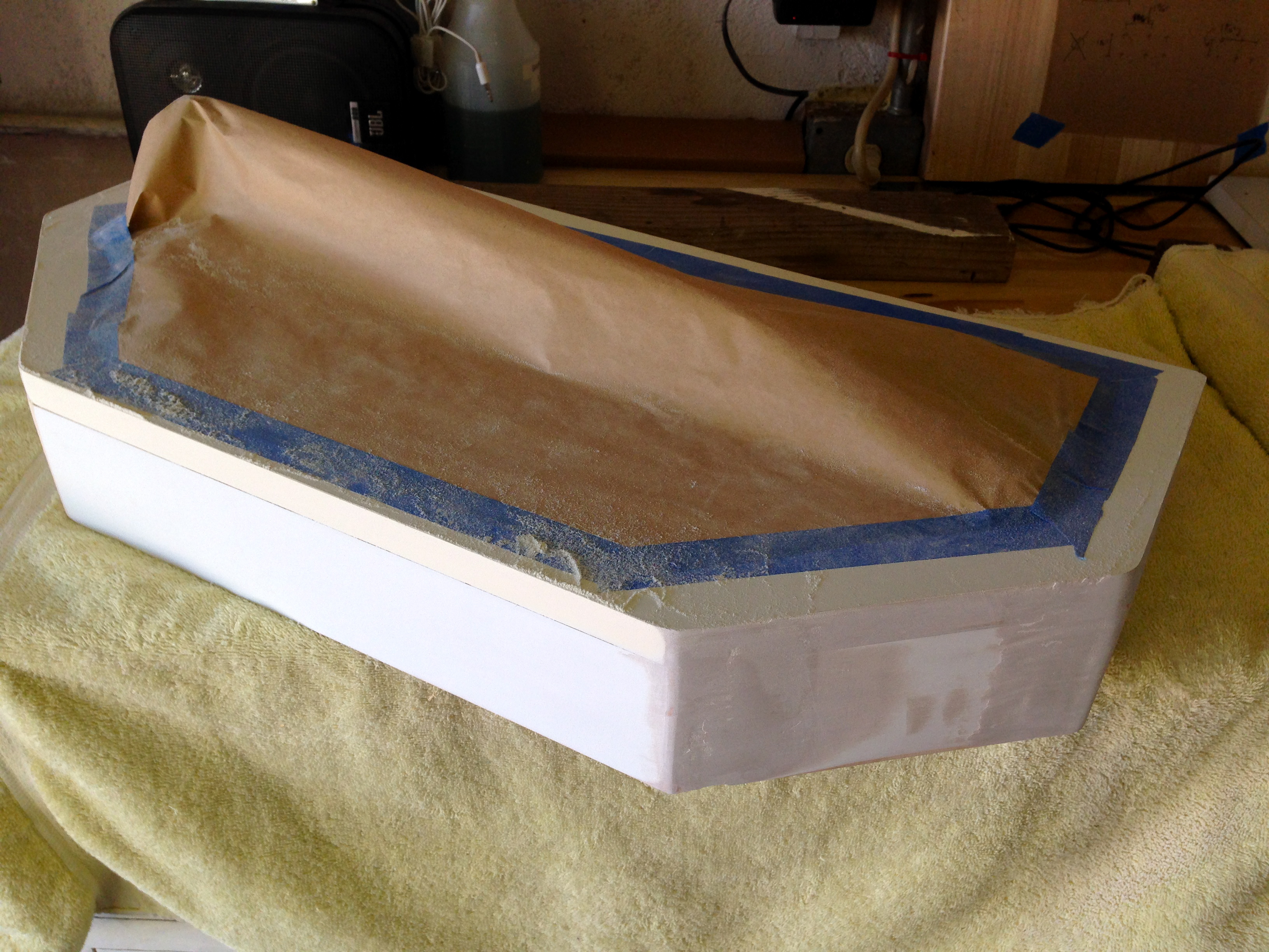
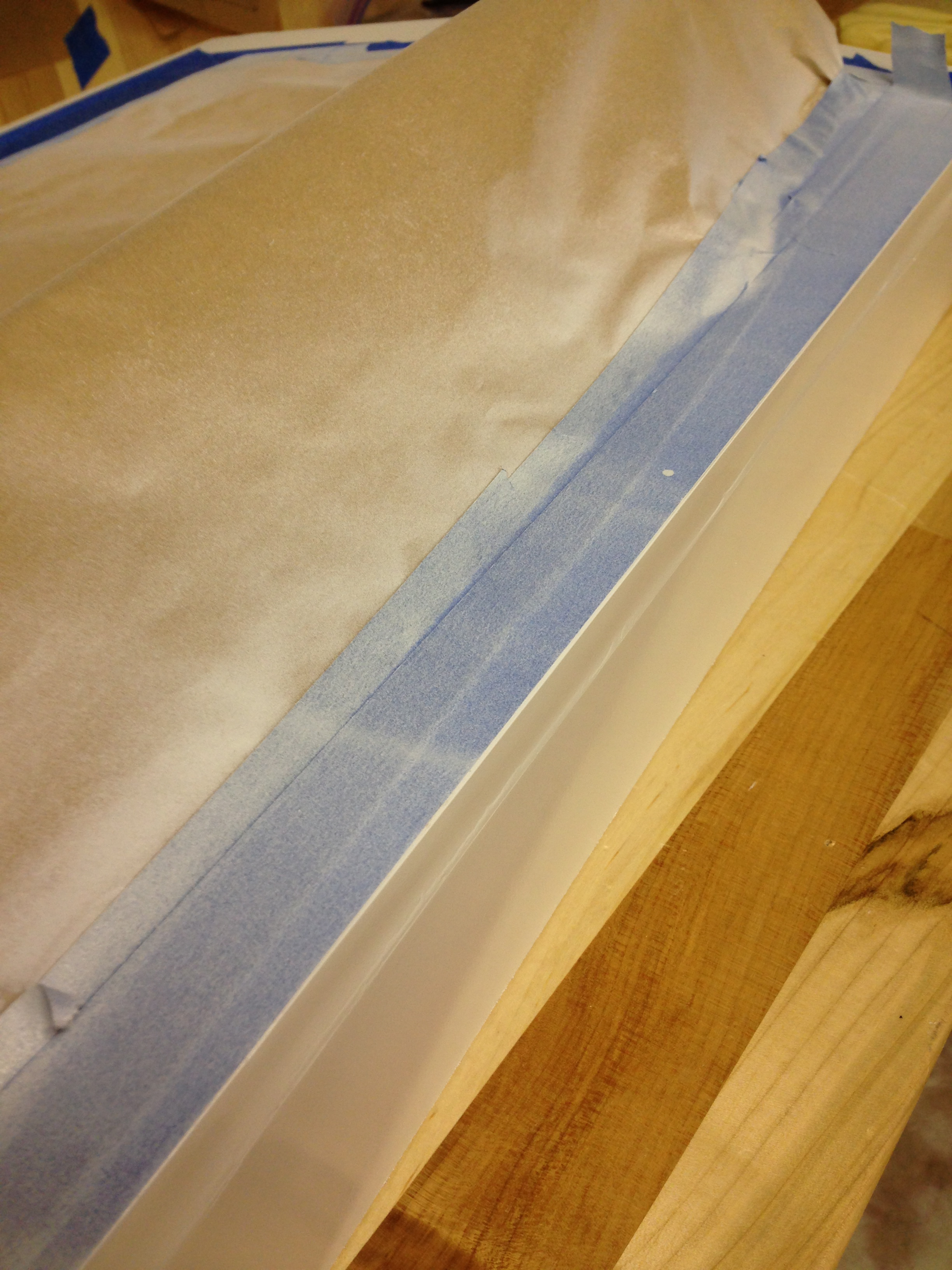
The next task was the body of the case. I used more of the melamine for this, but the nice finished surface would not survive this time. I am not a woodworker by any stretch, and I chose a challenging shape with a challenging material. Things were looking pretty rough, but luckily a good friend of mine put me on to a great tip for fixing shoddy woodwork- Bondo! Yes, the automotive body repair stuff. It’s an amazing hider-of-sins on all sorts of materials, including wood. Way better than wood filler, and cheaper than dirt.
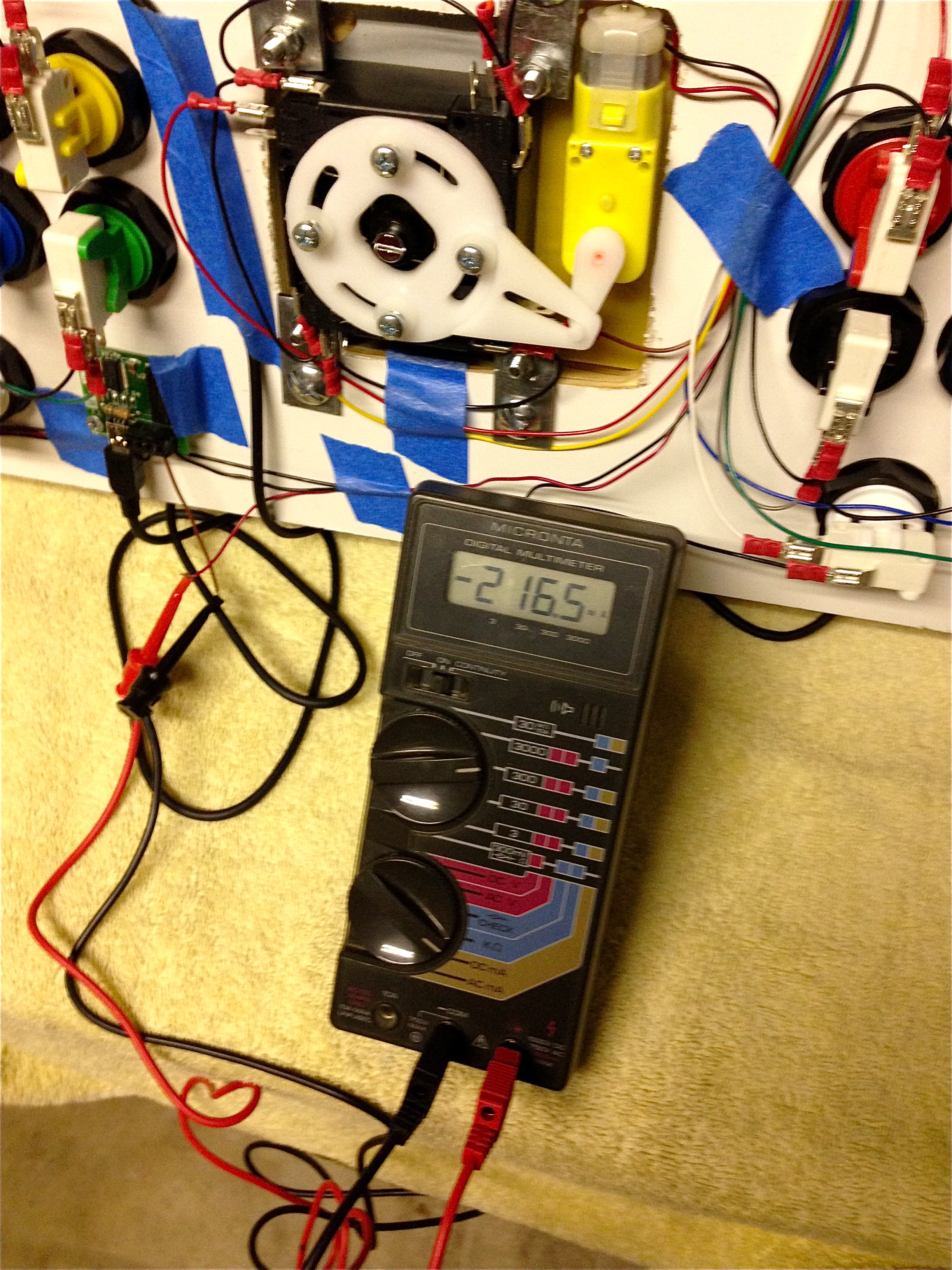
The next challenge was powering the Servo Stiks. They are intended to be run off a PC USB port, which can supply up to 500mA to a properly enumerated client device. However, I’m not going to be using them that way. The Servo Stiks have an optional Hardware Mode, whereby you replace the USB cable with a power source, and connect two buttons (or a toggle switch) to change modes. So, where to get that power?
First I needed to know how much power they need. I put the meter on them and ran them through some paces.
My first thought was to take the power directly from the same USB port as the encoder is using. However, this will be a passive, non-enumerated “device”. The maximum spec a USB port is supposed to supply for that is 100mA. We need more than that.
The next idea was batteries. The switching won’t occur very often, so as long as there’s no idle draw of current, batteries would last a very long time.
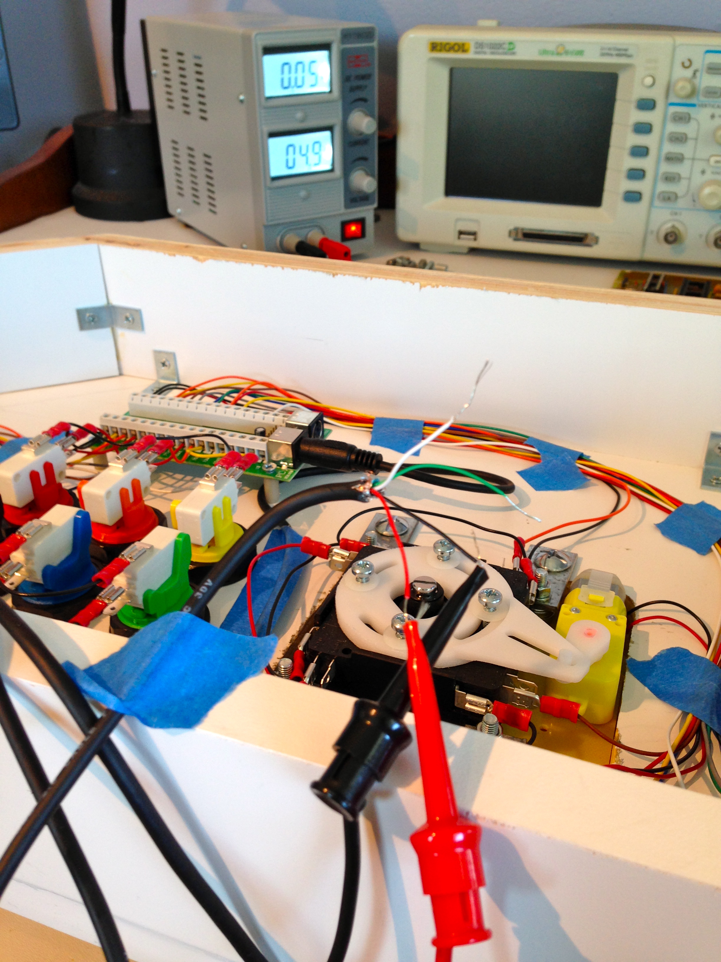
I was really trying to avoid needing a wall wart for this- I wanted the whole control panel to have a single USB cable coming out of it. After further research, it seems that most USB ports will actually let you draw more than 100mA- it just isn’t guaranteed in the spec. Well, what the hell- time to give that a shot. I knew for a fact that the USB port on my laptop would simply shut down the port if I draw too much current, as I’ve had this happen accidentally on other projects. It even throws up a dialog to let you know it has done so.

Well, huzzah! It actually worked great. Apparently the USB ports on my laptop will happily supply at least 220mA with no USB enumeration. So, I decided to strip the guts out of this cheap hub and build it into the design to supply juice to the Servo Stiks. It will give me power for the servos, and extra ports in case I ever want to add a spinner, trackball, or other widgets.
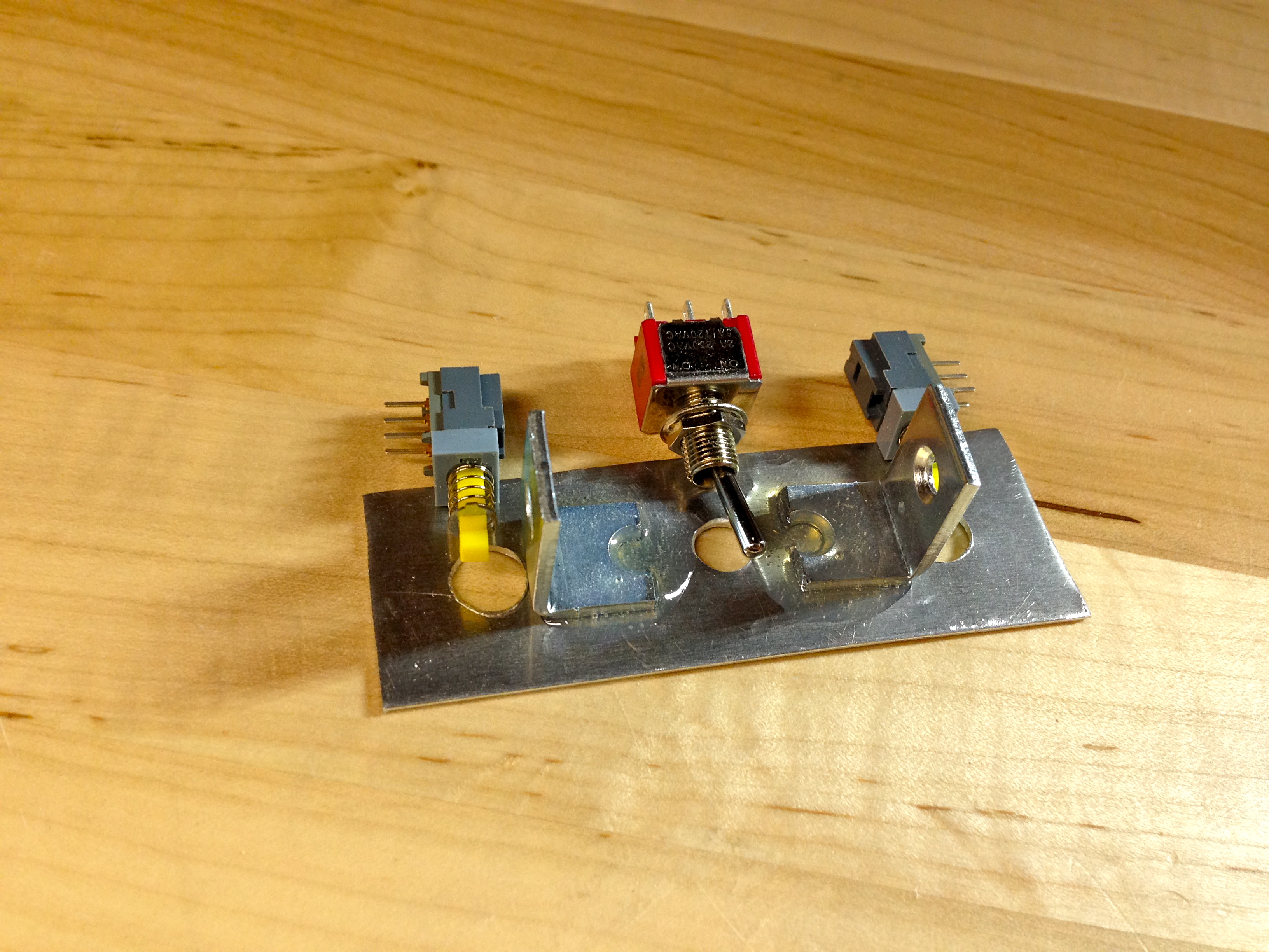
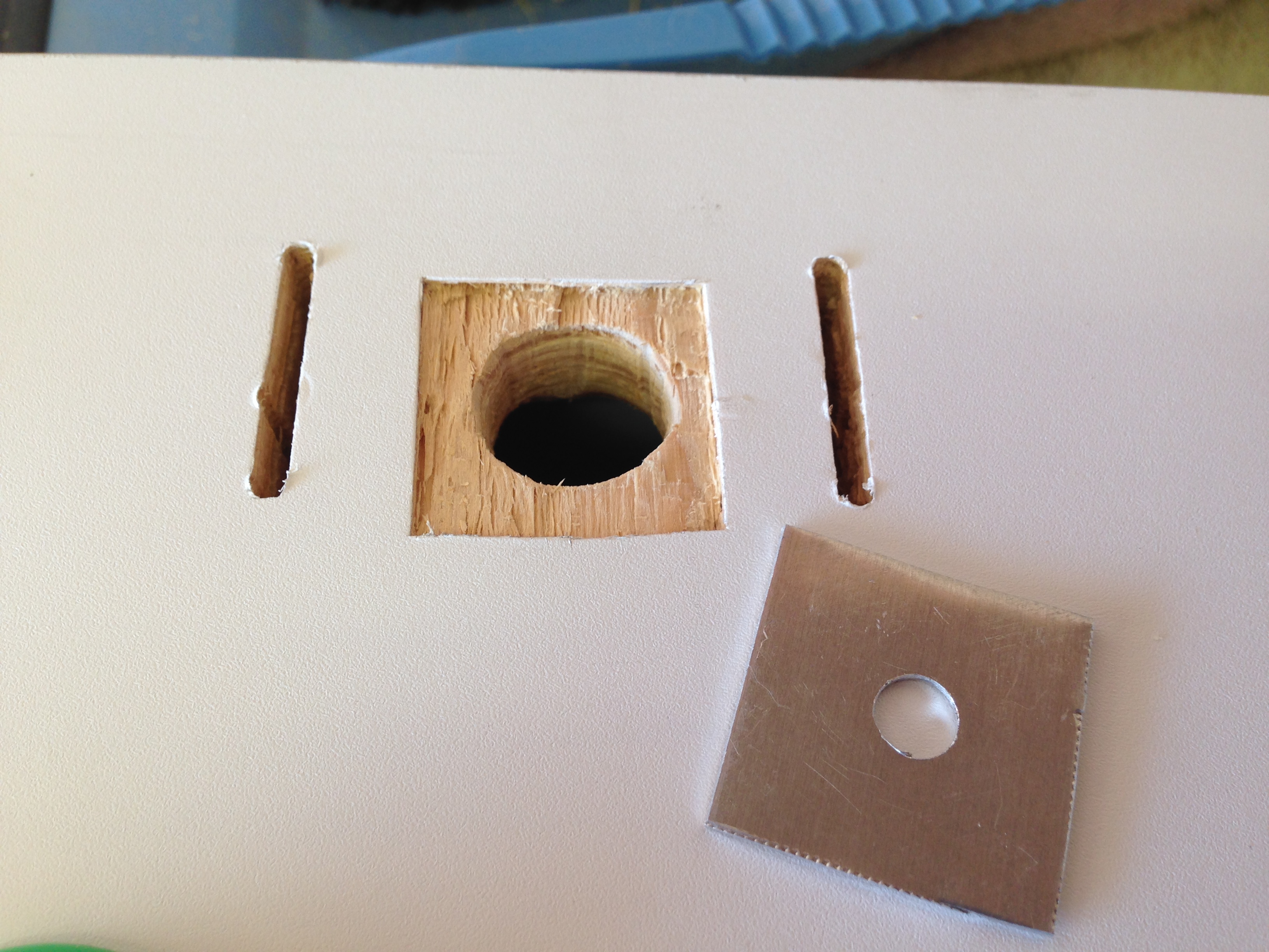
Next, I needed a switch to control the Servo Stiks. I planned to incorporate this with the coin buttons at the top of the panel, using a toggle switch. Toggle switches are nicer than buttons for an application like this, because the switch itself indicates the state of the underlying system. No LEDs or other fancy output required. Toggle switches need to be mounted in a thin metal panel though, and won’t work in a 3/4″ slab of plywood. I planned to inlay a small piece of aluminum to hold these controls.
First I needed to cut the slots for the coins.
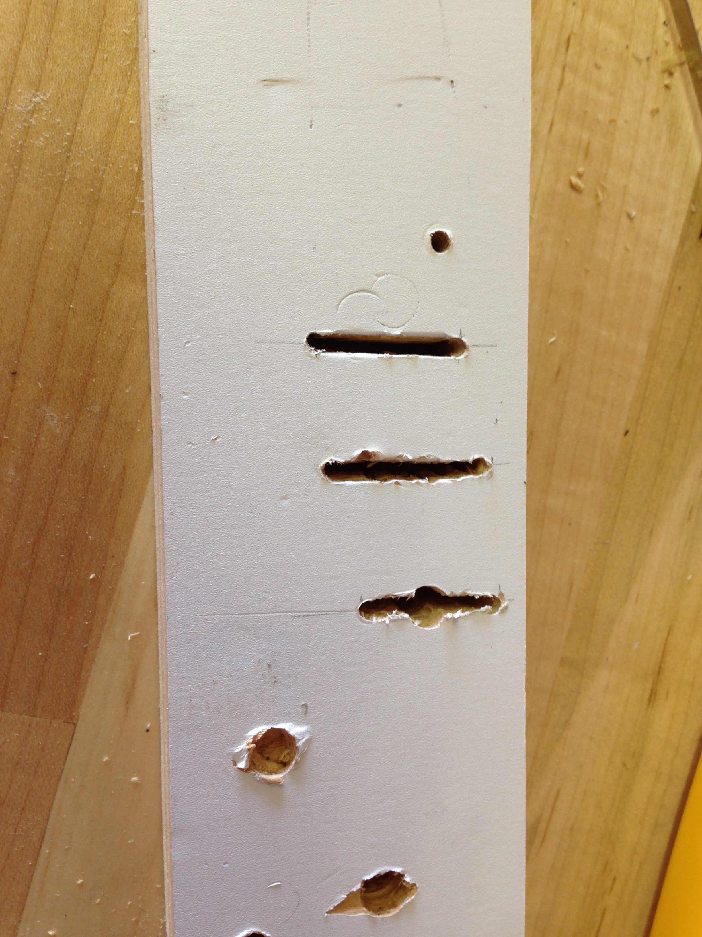
With the slots cut, I needed to mount some buttons underneath for the coins to hit. In my junk pile, I found some industrial switches similar to the Happs, but the mounting holes were too small for the hardware I had on hand. No problem, I’ll just enlarge them a bit.

Well, at least I got to see inside them! Interesting mechanism. I found another set of switches made of softer, less brittle plastic. These were quite amenable to being drilled out.
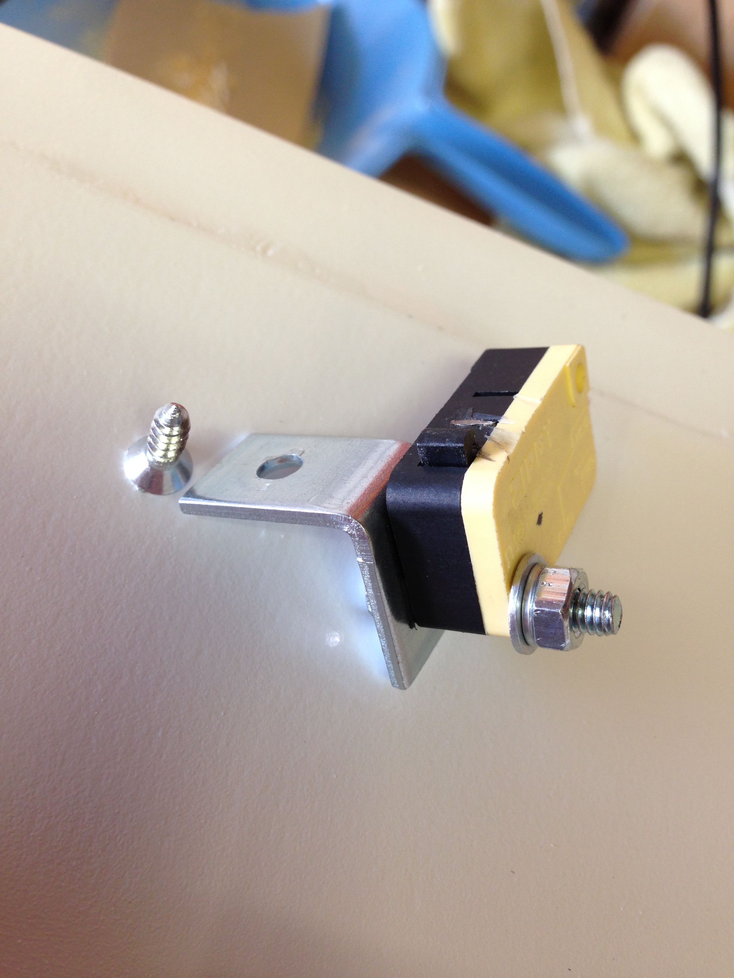
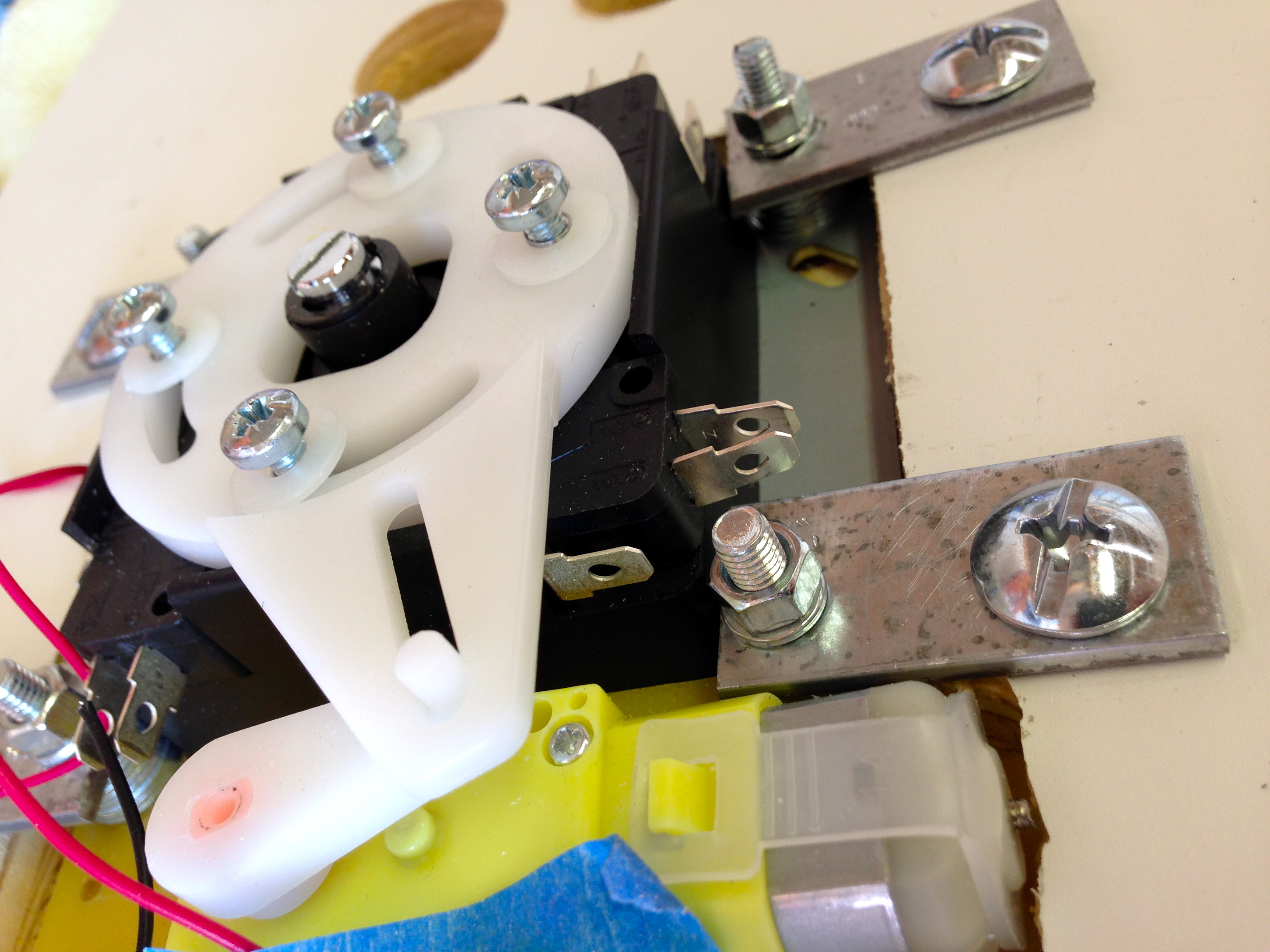
With the coin slots working, it was time to mount the toggle switch.
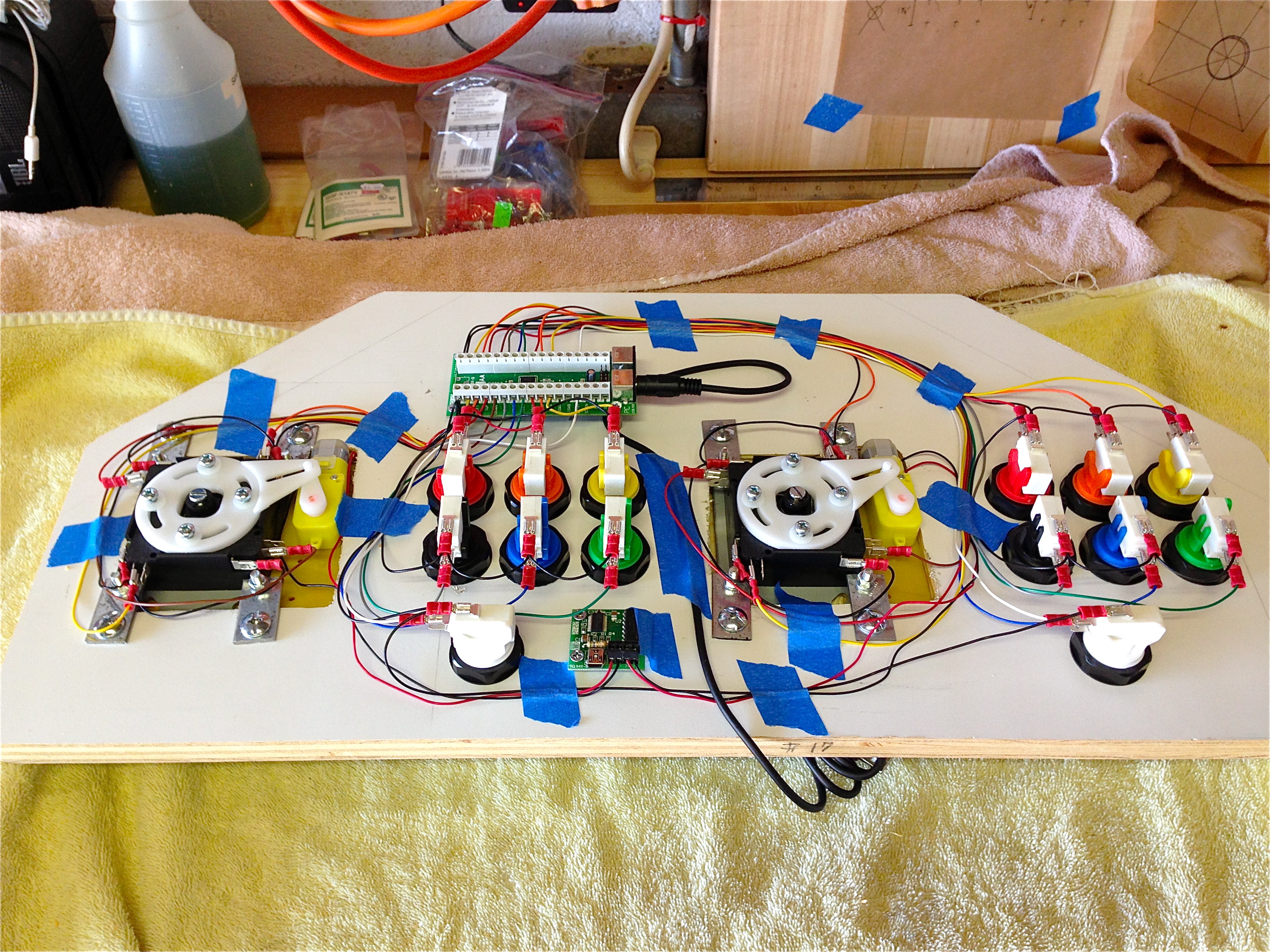
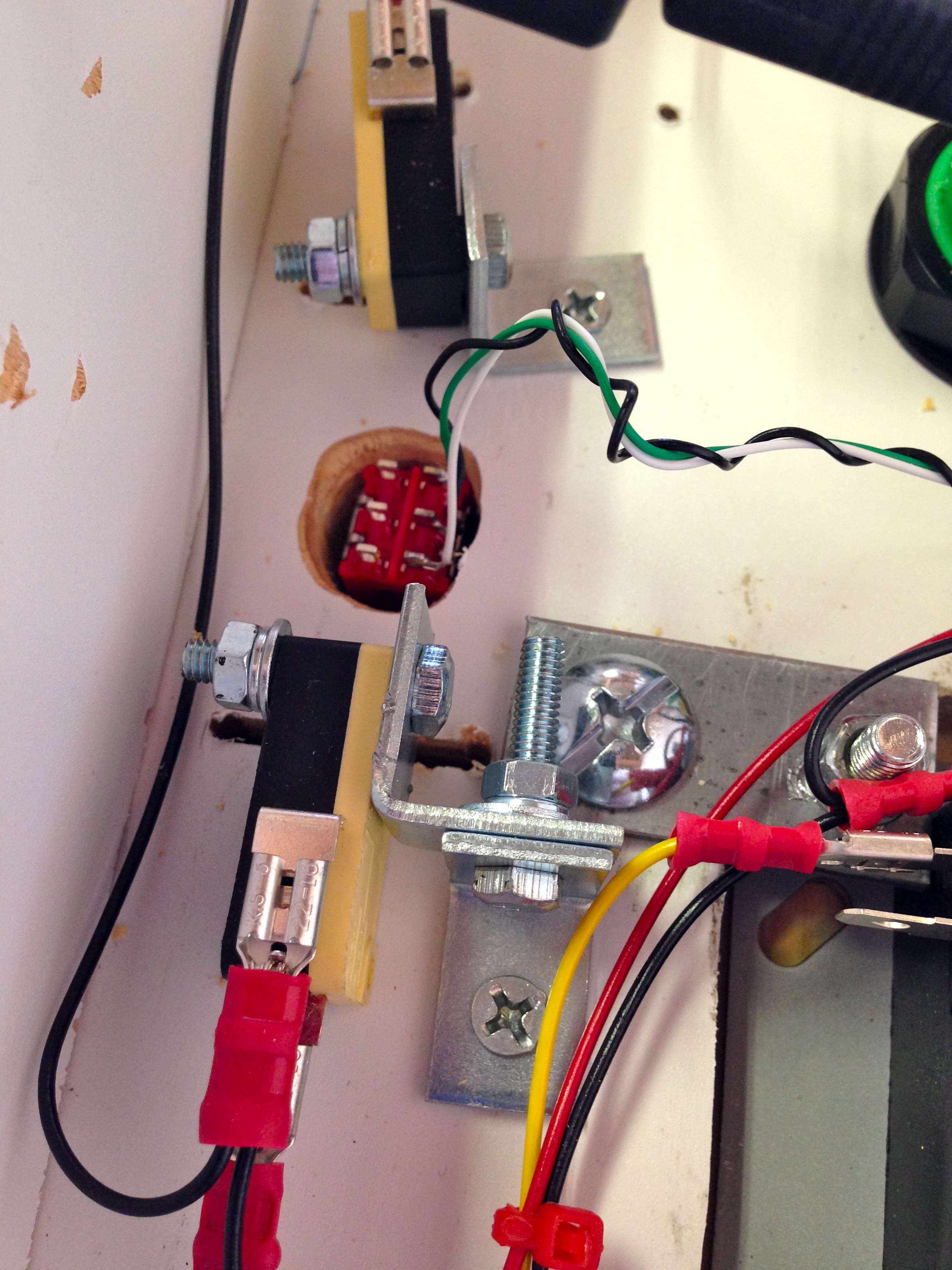
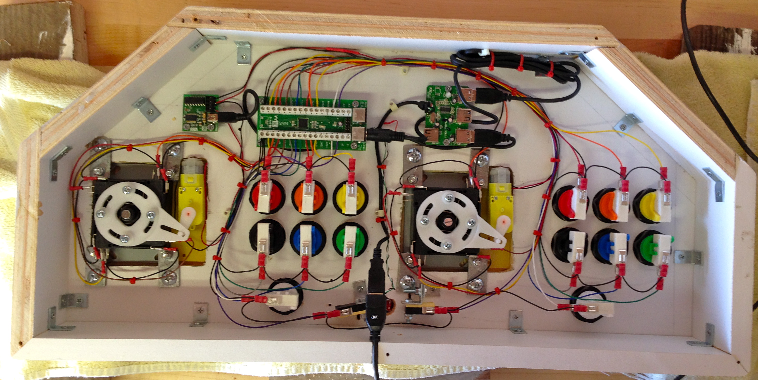
Here’s the finished interior of the control panel.
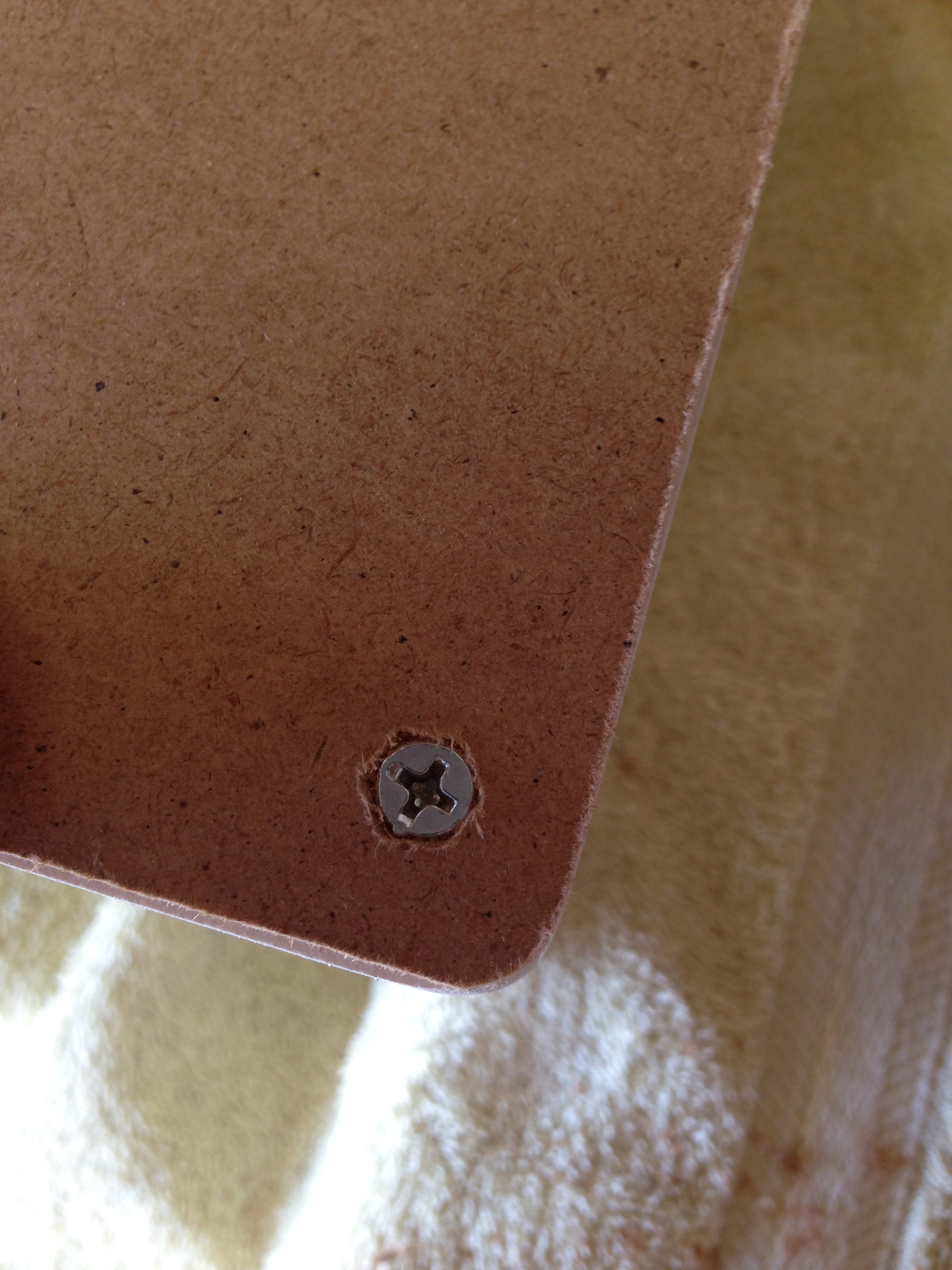
Almost done, now! We need a bottom. Once again, previous-home-owner to the rescue. He left behind a sheet of some kind of thin fiberboard. It seems perfect for the job- all I had to do was trace the control panel’s outline on to it, cut it out, and countersink some screws.
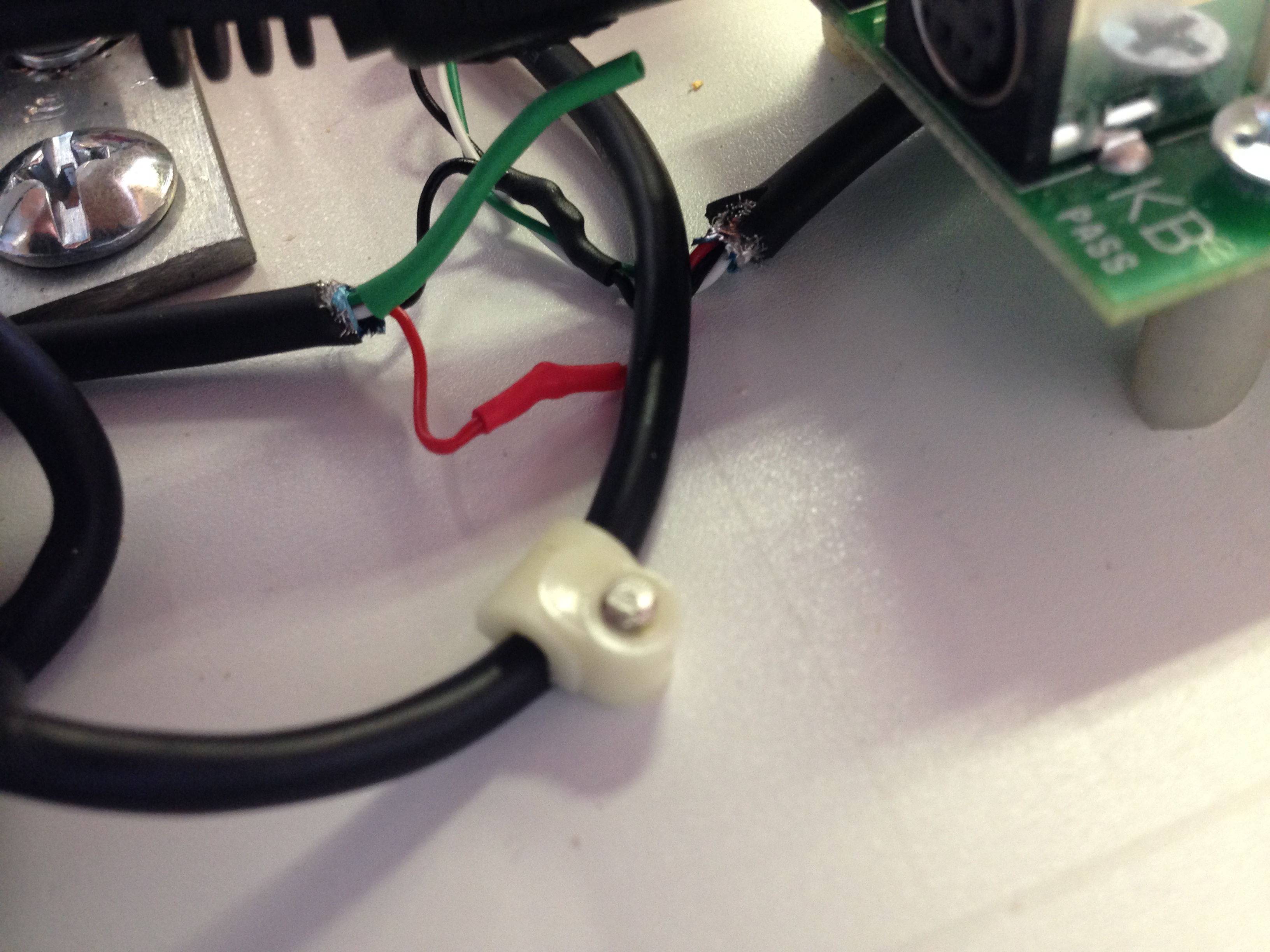
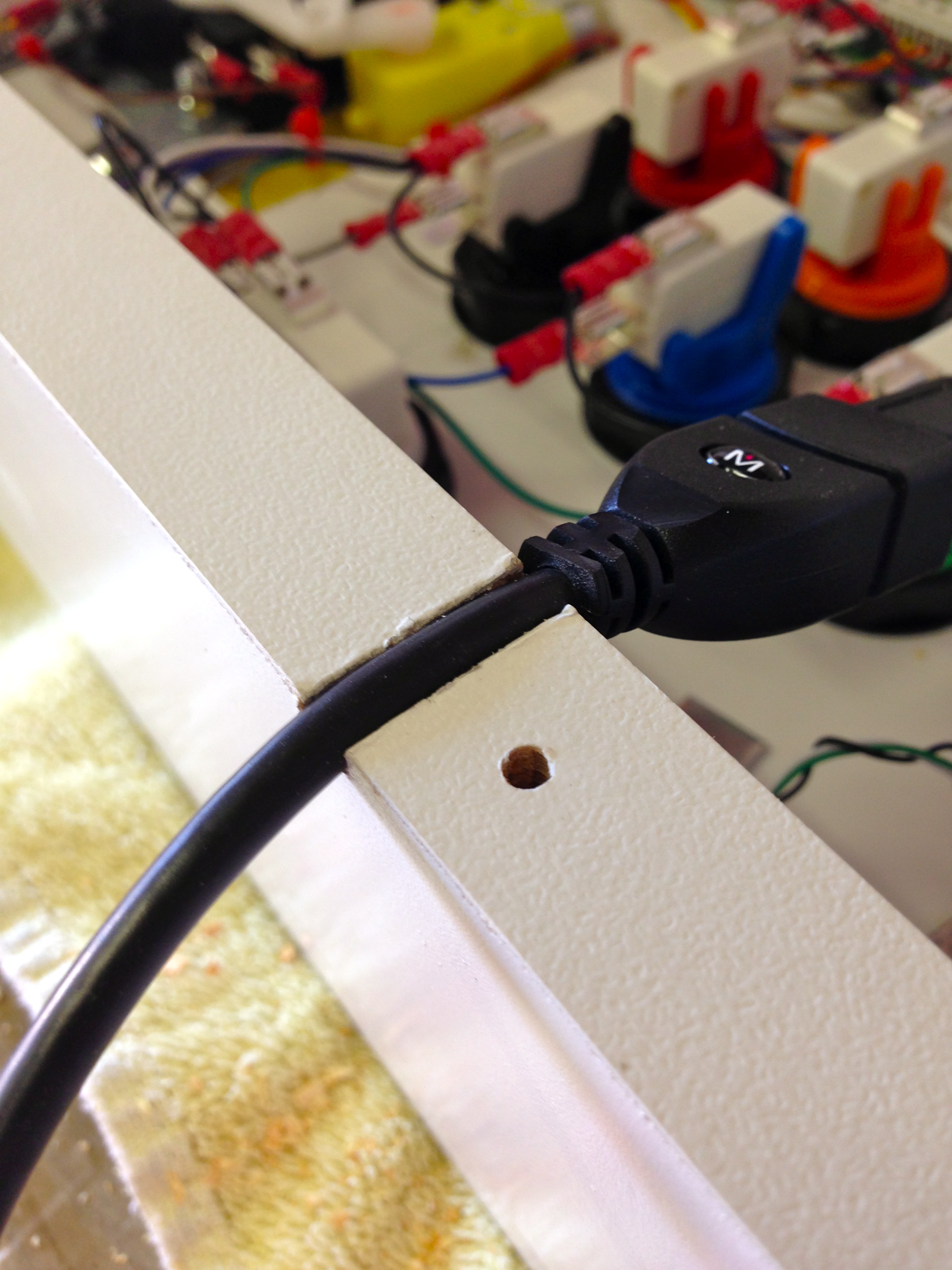
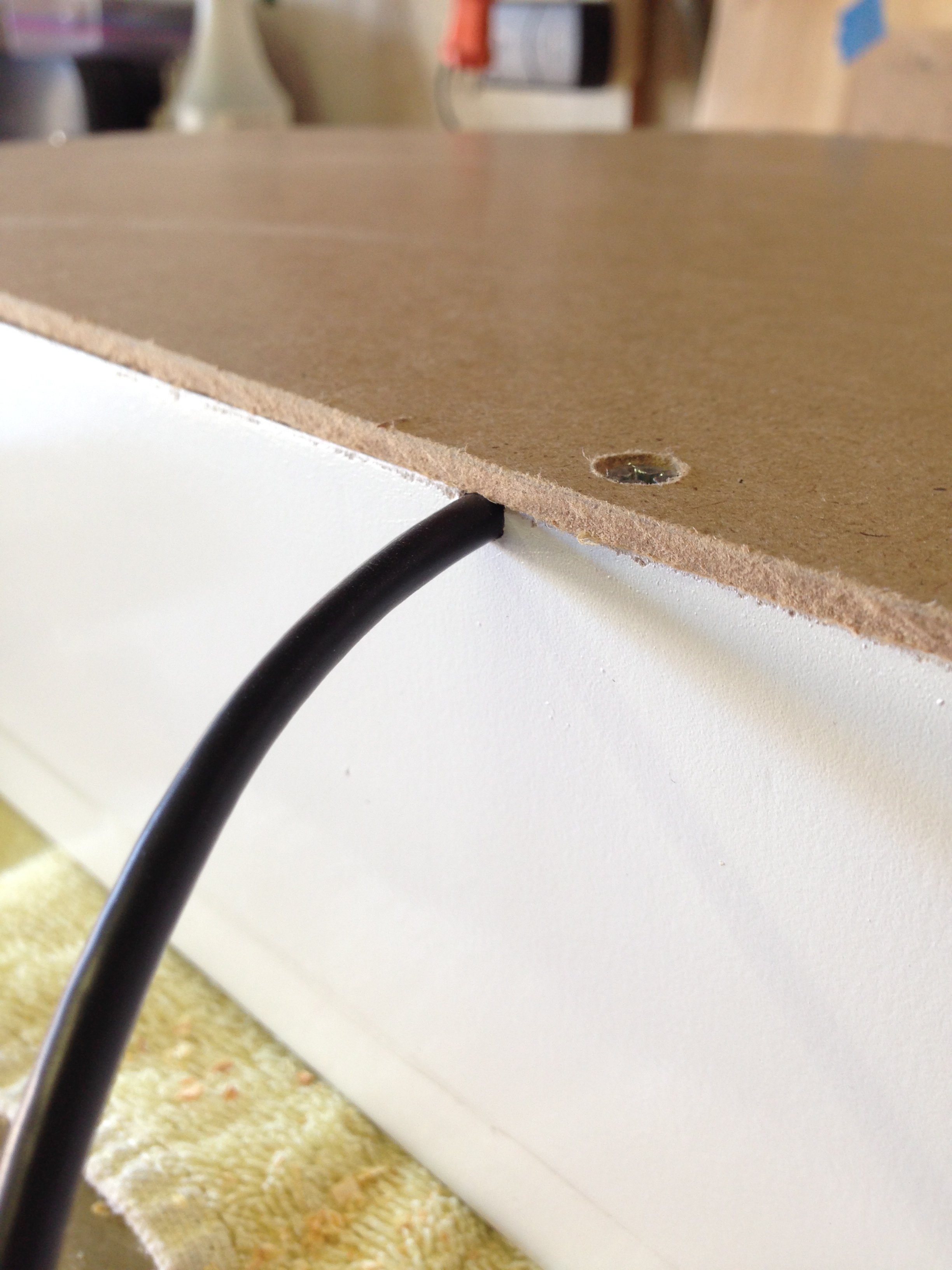
One more detail- the USB cable needs an exit point, and a strain relief. I decided to kill both of those birds with one notch.
Here’s some video of the Servo Stiks in action. First from the top, the way a user would see (and hear it). Next, a view from below with the bottom cover removed.
So there you have it. I’ve already played a ton of games with it, and could not be happier. The whole thing was made with found materials, so it basically cost me nothing beyond the arcade hardware itself.
Eventually, there will be a cabinet to go along with this, for the full stand-up arcade experience. For now though, I can just plug it into my laptop and get my classic game on. Round 1: FIGHT!
Hey Quinn, let’s play Contra 😀
I remember the arcade as the place that drained my coins as I was trying to figure out how to throw a fireball in Street Fighter 2… which we should also play!
hey quinn! drop us an email, we’d like to chat about projects with you! – limor
I’m clearly older than you because, strange as it may seem I never really got much into video games. I DID like Pacman and Ms Pacman, and maybe a few others, but it was the PINBALL machines that got the bulk of my quarters. My favorite machine was an electronic one called “Alien Poker”. I loved it when the sound synthizer cried out “Royal Flush!” Boy, I used to beat the tar out of that thing! I was a wizard on it!
A few years ago my wife and I bought a Gotleib “Jack in the box” machine locally that we found on ebay. I had to search the internet for new plastic targets and a gross of #47 bulbs, but I got it working again!
Indeed, there seem to be two types of people in this world- pinball people and arcade game people. I never got into the former, myself, though I did try. The mechanical aspects of pinball are very appealing, but I never got the hang of the skill set required to feel like I was in control of anything that was happening. It always felt like there was too much luck in pinball (though I recognize that’s just my lack of skill, not a fault in the game, necessarily).
It depends on the layout of the table, but pinball requires good eye-hand coordination and good reflexes. It takes a bit of time to learn the table, IE: just how much English you can give it before it tilts (that is adjustable by the operator!), the wear and polish of the surface change the ball paths in subtle ways, and like billards the ball bounces off the bumpers at various angles.
Pin games have been duplicated in electronic form on computer monitors (you could add accelerometers and gyroscopes to get player input! … hmm me thinks this might make an interesting project!)
There is something very satisfing about repairing an old pinball machine. The schematics for them are drawn like nothing else you’ve ever seen and take a bit of gray matter to figure out! On older games the color coding of the wiring harness is probably faded (and we are talking two or three different colored strips on each wire!). Then you are dealing with EML (electro mechanical logic!). In some cases, you have to rebuild relays by replacing broken contact blades, or lost springs. In a way, a pin game resembles some of the early computers that Grace Hopper might have worked on!
http://www.youtube.com/watch?v=SX-iZdnMeYA
Hmm.. Well, then “I go both ways” although I have to say, I’m about 75% Video game, and only 25% pinball.. And, the sweetspot for me is the timeframe between pong to Joust or so.. Never got into the fighting games, neo geo, etc.. Pacman, Galaga, Burgertime, etc..
Oh well.. Beautiful control panel.. I was wondering about those motorized sticks for the build I’m just starting. I think you’ve convinced me they’re probably worth it after seeing them in action!
Nice job!
-Steve
… I mean pacman/joust are the good ones.. 🙂
Yes, I can recommend the Servostiks. They did need a little massaging to work smoothly. I removed the restrictor plates and sanded the black tabs on the joysticks that retain it. They tend to bind up a bit. Also, make sure all the springs on the screws aren’t getting caught. They tend to slip down into the slots.
One question… When switching from 4 to 8, why did the sticks move at different times? Was that on purpose to conserve current? If so, how, and if not, do you know why one lags? Not a big deal, just curious..
Yes, the sticks switch sequentially. This is a feature of the control board which is probably to keep the peak current below 500mA (the most one can reasonably hope to get out of a non-enumerated USB device).
The Neo Geo has some fun shooting and racing games: Aero Fighters, Neo Drift Out, Captain Tomaday, Metal Slug.
That looks like it was a fun project. 🙂 Neat sticks, with the servo mechanism. I didn’t know such a thing existed.
Great article.
Don’t mean to be picky but … those of us “of a certain age” have certain compulsions we cannot control … that should be “rite of passage” …
Thanks! Corrected. I do aim for quality here at Blondihacks.
There was no reason to use a dremel to cut the metal lever off of the microswitches, all you had to do was pry the two halves apart slightly.
The Dremel is its own reward. 😉
I can haz gameplay video?
I’ll do some video when the rest of the system is up and running, I imagine. Right now it’s not very visually interesting- just a giant controller plugged into a decrepit old laptop. 🙂
I hope you’re going to make this work with your Veronica computer. C64 had it’s wimpy TAC-2, Veronica should have this awesome arcade controller.
Anyways, nice work!
Veronica isn’t… done… is it?
Nope, not yet. I need to step away and work on other things sometimes, though. Don’t worry, Veronica will be back on these pages.
I love the “coin op” buttons. I’ve been mulling a controller build myself and will definitely be including this. Thanks!
Hi Quinn,
Congratulations on your control panel!
I must admit that when I heard about your work on ‘No Quarter’ I feared the worst – Have you heard of a ‘Franken Panel’? It’s what the arcade collectors call an abomination of a control panel with a hundred buttons, spinners, flight sticks, toasters etc all squished on to an aircraft carrier sized panel. I was so glad to see a really neat, well made control panel when I went on your site! I always liked the idea of the servo sticks, as 4 way games are REALLY 4 way and 8 way are REALLY 8 way – you can’t compromise.
Your next build?…A whole cab?
I’m nearly finshed my 2nd build -this time a full size Donkey Kong (as they are so hard to find for less than £800 in the UK)
cheers!
V
*off to look at the rest of your site – I particularly liked the ‘are you even a girl under that shirt’ ‘toon 🙂
Indeed, I encountered the Frankenpanel phenomenon during my research. I even found a couple of blogs devoted to them. I certainly wanted to avoid that, and I also wanted to start small(ish) for my first attempt at this. In my experience, it’s better to set one’s sights lower to ensure the project gets finished. Otherwise large half-done projects just pile up all around.
I do have cabinet plans for this stick, for sure. Stay tuned!
I forgot to say – you might want some ‘coin bezels’ to hide the coin slots a bit. The chrome ones on a Sega Naomi machine would look nice on there…
I use a leaf switch under the reject coin button on some of my machines for a coin input – not as cool as an ACTUAL coin – 10pees in my case 🙂
Not a bad idea! I was going for the most naked look possible, with no frills to speak of. I tried to avoid decorative elements of any sort. However, pulling that off requires flawless workmanship, since you can’t cover imperfections with bezels and such. My coin slots are a little rough viewed up close, but in person they look better than in the video.
I’m not sure how you feel about a router – they certainly make much more accurate and clean slots, but they can be dangerous beasts! – I’m a CNC miller by trade (a massive computer controlled automatic router of sorts) so I’m fairly used to evil machines 😉
You can do all sorts with a router – I mainly use mine for routing panels and t-molding though. If anything more involved is required, I chuck it on my machine at work…
Yes, I used my router to mill out the recessed areas the joysticks mount in. I considered using it for the slots, but there were a number of issues:
1) I didn’t have a bit small enough to cut the coin slots
2) Because of the depth needed, it would have taken an awful lot of passes (my router is pretty light duty, and will only do 1/8″ depth in one pass)
3) Because of the small size, I wasn’t sure I could do it precisely without a whole lot of setting up fences and such
4) My earlier experience with routing melamine taught me it tends to tear up the finish around the cut
The nice thing about the chisel method is that it guarantees no damage to the surrounding finish. A smaller chisel would have done a perfect job, but my smallest one was a little too thick to make it half-way through the material (I chiseled in from both sides). I had to finish with some drill hogging, but that did do a teeny bit of damage to the edges of the slots.
Before I forget:
“You could lash your horse to these sticks, and he’d still be there in the morning (though he may have beaten your Moon Patrol score by then).”
Never mind the joystick. You win the Internet for that quip alone.
😉
The thrilling strains of the Moon Patrol background music running all night long… horse aside, you’re going to have madness issues. 😀
Luckily, I’m already quite mad. Nowhere to go but up.