Some Input to go with all that Output.
There are moments in a big project like this that really stand out. Those moments where it all seems to come together, and…. magic happens. This is one of those moments. After some rough times on Veronica as of late, it was great to have a win. This is going to be a long piece, so grab a nice local microbrew and get comfortable.
As you’ve already surmised from the title, it was time for Veronica to get some input, in the form of a keyboard. My goal throughout has been for Veronica to get along in the real modern world. That’s why I put all that effort into VGA, even though composite video would have been easier. Composite displays are just getting too hard to find. As I’ve said before, Veronica is basically being surrounded in a “1980s bubble” created by fancy interfaces to convert modern tech down to her level. The keyboard interface is another great example of that. In this spirit of getting along, I wanted to support modern USB keyboards. Most homebrew projects go with a PS/2 keyboard, or a serial terminal, or something custom, because those are all easier. The 1980s home computers had it “easy” in a sense, because they all had custom keyboards built in, so the designers could make them produce whatever signals were most convenient. We have no such luxury here.
I also decided I wanted to use the 6522 Versatile Interface Adapter (VIA). This is a general purpose I/O chip that was part of the original family of 65xx chips. It’s designed to work with the 6502, and it’s “period correct”, if you like. I picked up a nice set of W65C22S chips from Western Design Center, who still makes this modernized version. So, the challenge boils down to getting a USB keyboard from 2013 to talk to an I/O chip from the 1970s. Never a dull moment on Veronica.
I started by researching USB hosting, and what it takes to implement that. It turns out, quite a bit. USB is a very complex protocol, and while implementing a peripheral is fairly straightforward (nice single-chip solutions exist), implementing a host is considerably more involved. I found some expensive multi-chip solutions, but it wasn’t going to be easy. Then I stumbled on to a great alternative, as long as you only want a keyboard (as opposed to general USB connectivity).
It turns out that, thanks to globalization, virtually every USB keyboard out there uses the same USB keyboard controller chip. That chip has legacy goo in it for those old USB-to-PS/2 adapters that every PC in the 1990s came with. During that transition period from PS/2 to USB, this backward compatibility was essential, and it turns out the chip makers never bothered to remove it. I’m told some hardcore gamers still use these, because apparently PS/2 keyboards have some superior characteristics with regards to handling multiple keys being down at once, compared to USB.
Anyways, what this means is you can basically implement the much simpler PS/2 keyboard protocol through a female Type A USB connector, and it will just work. Of course, you end up with a “Keyboards Only” USB port, and chaos might ensue if you tried to plug anything else into it. For us homebrewers, though, that’s fine. The main thing is, it achieves my goal of being able to pull a modern USB keyboard off the shelf, plug it in, and have it work. There’s a trivial trick you need to do to force the keyboard in PS/2 compatibility mode. I’ll explain that in a minute.
So, with that USB problem “solved”, it was time to figure out the PS/2 protocol. There are some great resources out there on this. My favorite is the OSDev Wiki. The executive summary is that each keypress sends an 8-bit scan code to the host when it goes down. When the key comes back up, it sends a special prefix byte (usually $F0), followed by the scan code again. There are also some more exotic packets for special keys, but we can safely ignore them. The nice thing about the PS/2 protocol is that it degrades gracefully. Many special keys, for example, are two byte packets prefixed by $E0. If you simply ignore that prefix byte, the scan code will be interpreted as the second byte of the packet, which will map harmlessly to some other key. That won’t mess up any internal state in your driver (if you code it carefully), it just means the Page Up key might return a ‘9’.
One minor catch with all this- PS/2 devices are serial devices. That means they send 11-bit RS-232 style packets that need to be stripped of all their extraneous bits. We also need to be aware of what happens when the keyboard is first connected. The USB chip in the keyboard sends out a bunch of negotiation bytes. The handy part is, it if doesn’t get the proper replies to those bytes (as per the USB protocol), it falls back to PS/2 compatibility mode. So, that “trick” I mentioned earlier is simply “inaction”. That’s good, because inaction is something I’m really great at. If doing nothing was a professional sport, I’d be internationally ranked.
The point of all that is, we have a few housekeeping tasks we need to perform on the data coming in from the USB connector. When I see a job like this, I think microcontroller. I’m a big fan of the ATTiny13, and I tend to throw handfuls of them at the breadboard until the problem goes away.
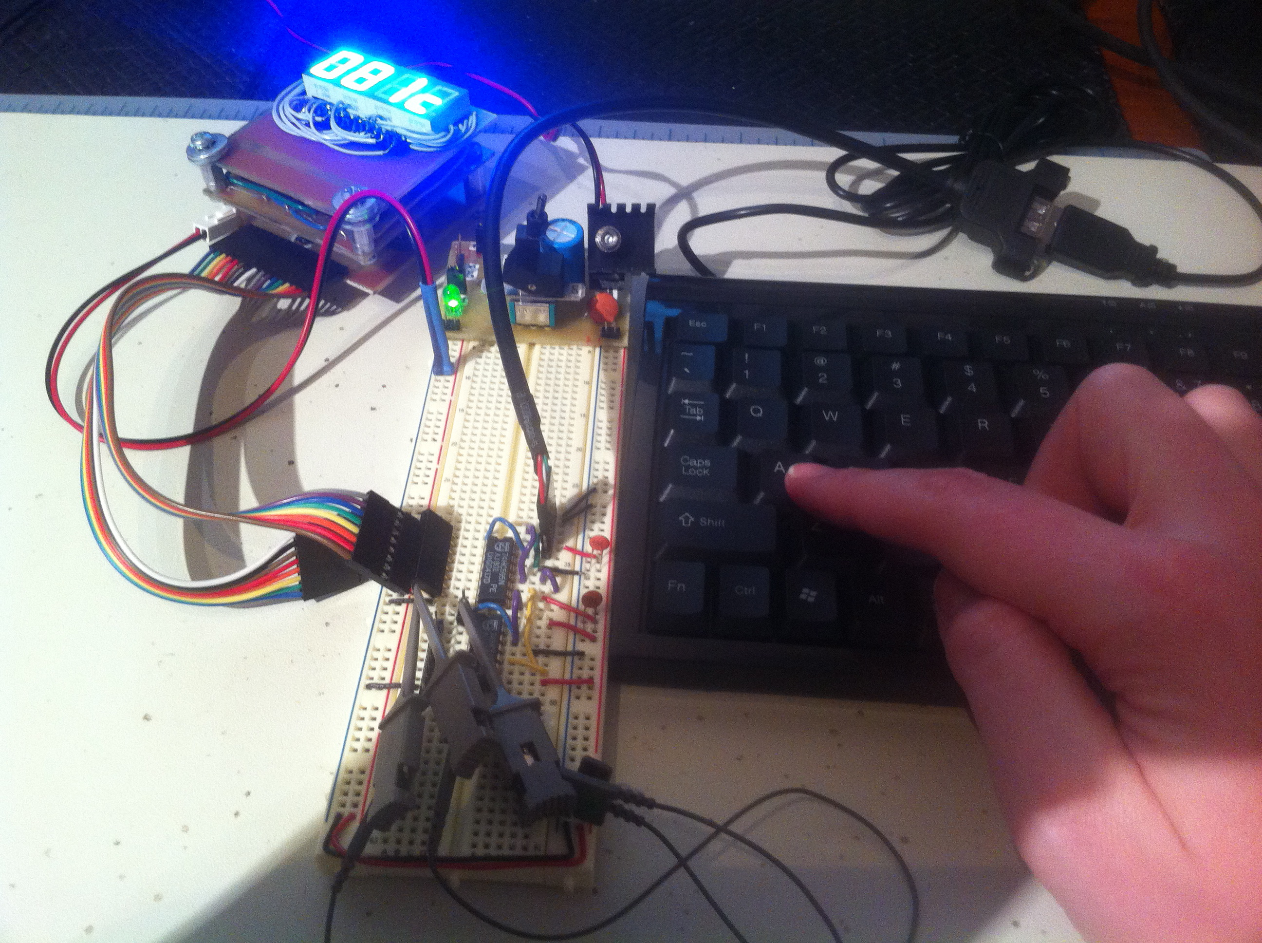
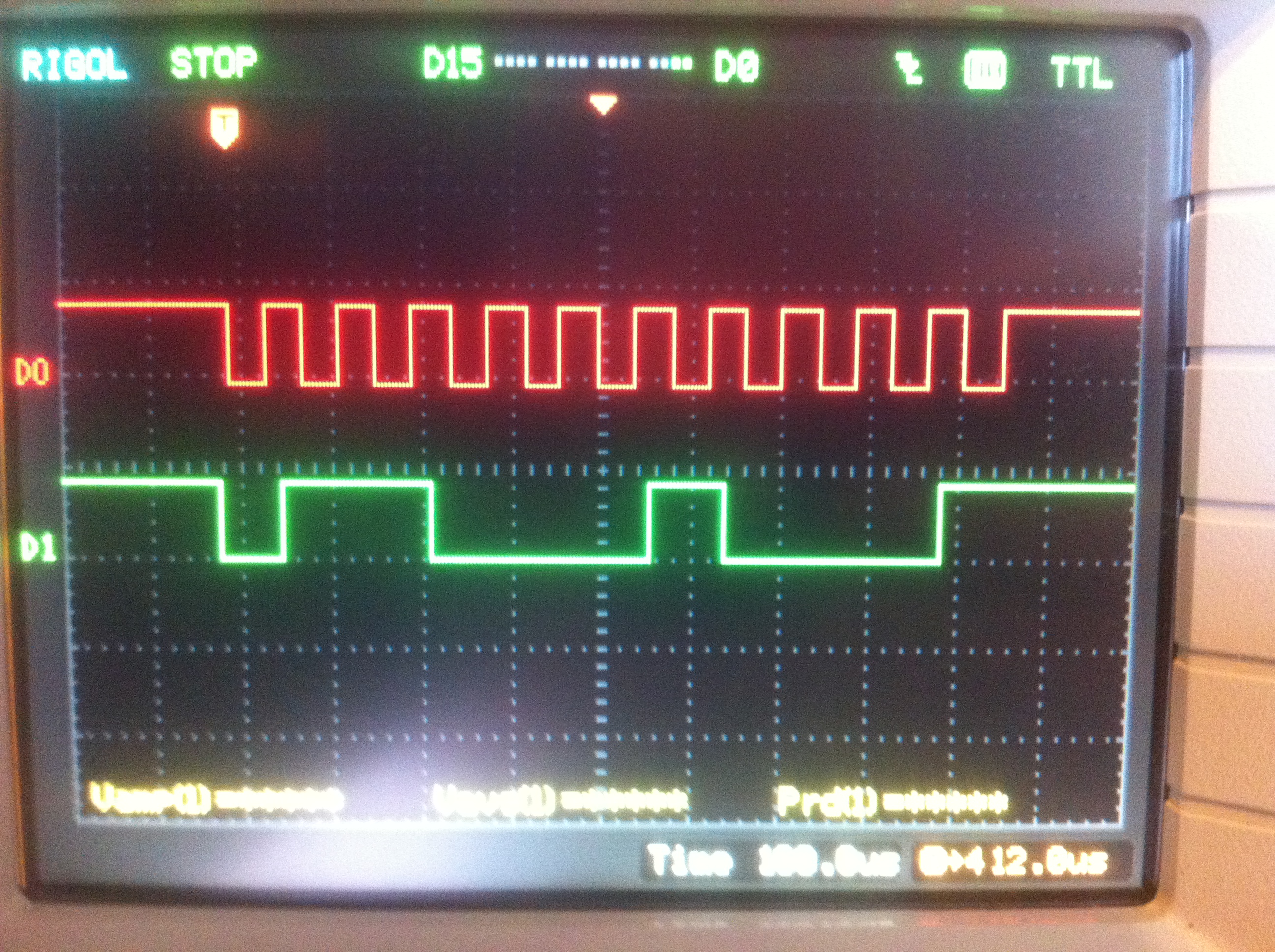
To test this approach, I set up a breadboard with the USB connector, an ATTiny to read the data from it, and a shift register to push the bytes out to HexOut. That would allow me to see exactly what the keyboard spits out, and how I can work with that data. Connecting to USB is easy- it’s just power, ground, D-, and D+. In PS/2 compatibility mode, the keyboard uses D- for data, and D+ for clock. New Egg sells a really nice USB socket that ends in a 0.1″ header. It’s perfect for breadboarding USB experiments.
The keyboard, being an input device, might start clocking data out at any time. That means we need to respond with an interrupt handler on the ATtiny, so we don’t miss anything. Here’s the code that I came up with to do that:
That code sets up an interrupt handler that listens for clocks from the USB connector, then buffers up 11 bits, strips off the start and stop bits, and holds the remaining 8 data bits. The code then uses a couple of other pins on the ATtiny to manage a 75HC595 shift register, which is used to convert this serial data in an 8-bit byte usable by the 6522 VIA. The ATtiny is acting as the glue and signal converter between the USB and the 6522.
So, now that I can get data to the VIA, the next piece of the puzzle is interfacing the VIA to the 6502. This could not be easier, since they are designed to work together. If you’ve worked with microcontrollers, it will seem very familiar. The VIA provides “Ports”, timers, and other facilities, which are all memory mapped into the 6502’s address space wherever you like. The interface uses Data Direction Registers and such, just like a microcontroller. I just need to connect up my shift register to provide the keyboard data, add a little address decoding, and throw the whole thing on Veronica’s main bus. Here’s the circuit I came up with to do that.
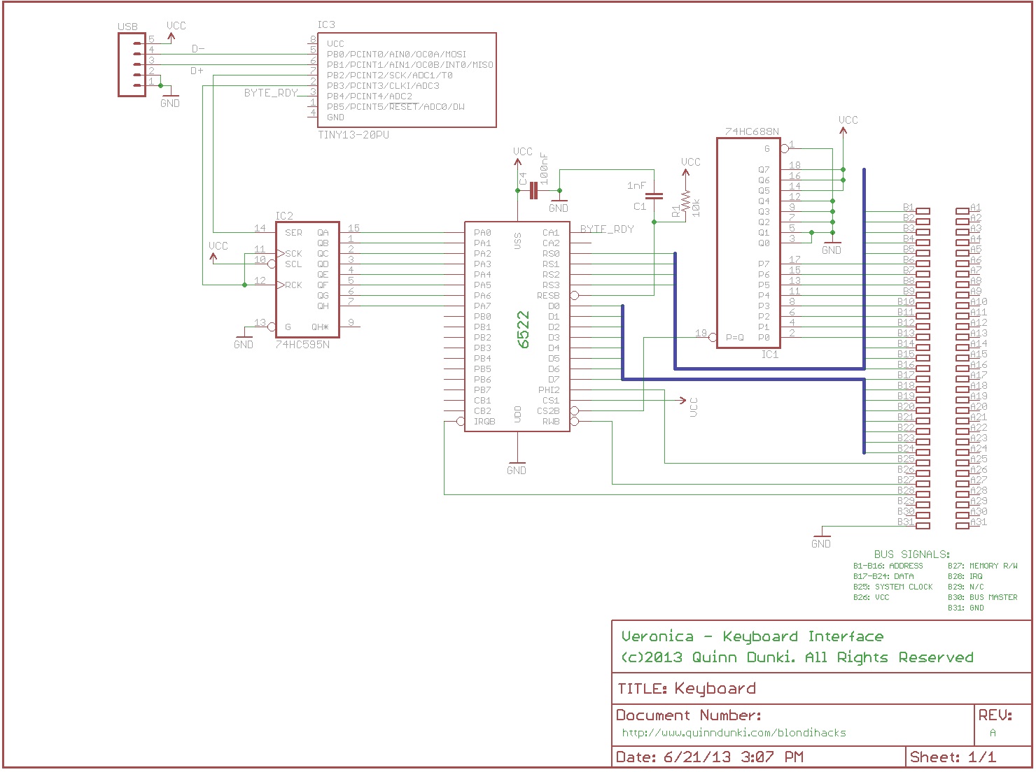
Note that I could not find an Eagle symbol for the 6522, so I made one. Here it is, free to use, if you like. The schematic above is a work-in-progress, hence a few missing details like decoupling caps and power/ground connections. The VIA has a lot more room for other I/O on it, so I’ll be adding more stuff to this before I finish it up and etch a PCB.
The address decoding is handled by a single 74HC688 8-bit comparator. All addresses in the $E0 page are reserved for I/O in Veronica’s memory map, so this is a nice one-chip way to do decoding. The low address bits are routed to the 6522’s internal address bus, which is how you map its registers into the 6502’s address space. A very elegant design by those wily WDC engineers.
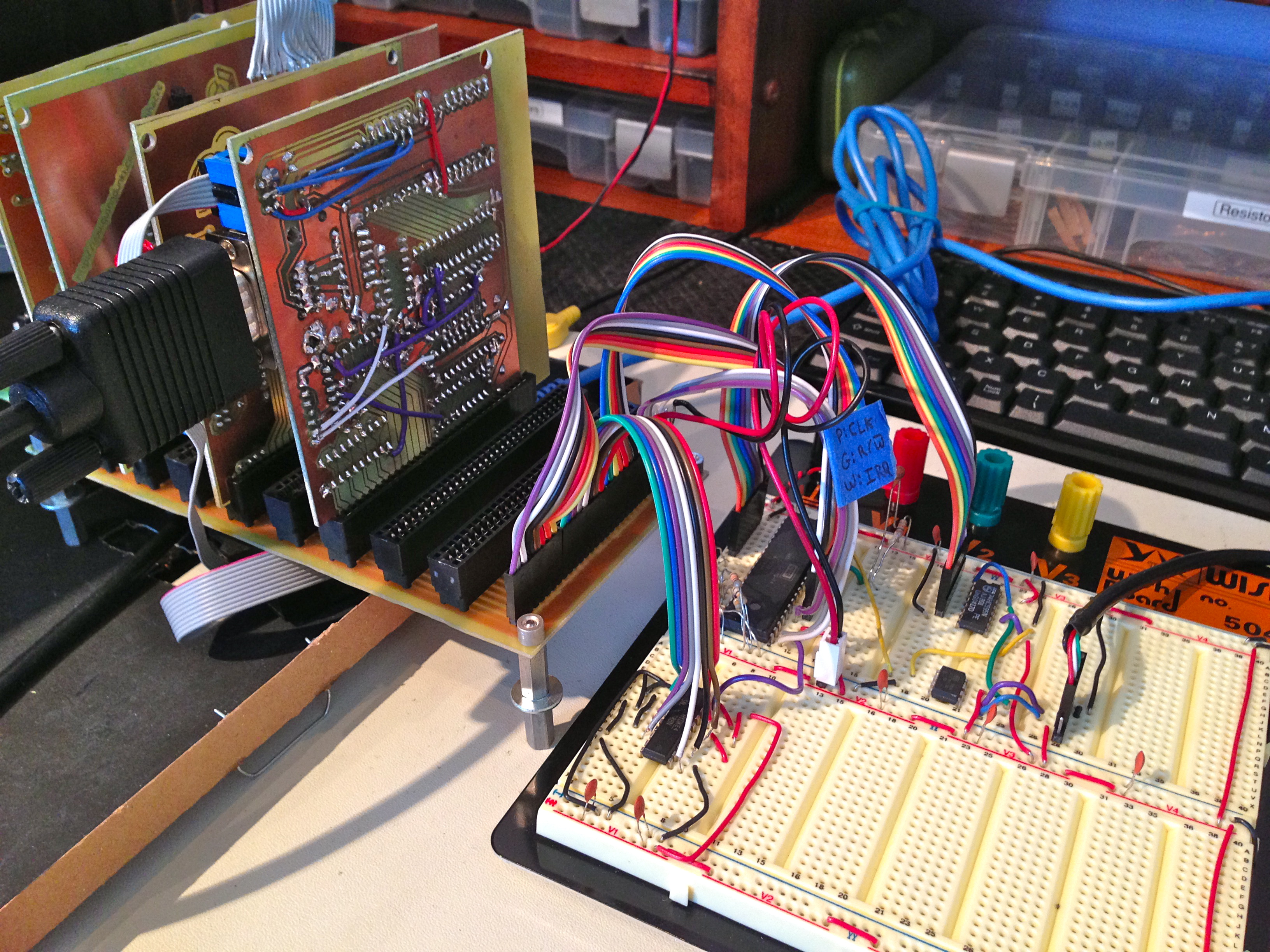
With that design figured out, it was a simple matter of prototyping it on the breadboard and working the kinks out.
When the ATtiny has received a byte from the keyboard, it presents it to the 6522 (using the ‘595), then signals the data is ready using the 6522’s CA1 line. The 6522 datasheet explains very well how to do all this. When the 6522 receives the keyboard byte, it signals the 6502 with an interrupt. So, the next thing we need is an interrupt handler in Veronica’s ROM.
The secret to a good interrupt handler is speed- get in, do your business, and get out. In this case, all I do is grab the byte and buffer it for processing elsewhere.
To debug this, I wrote a routine to print out the hex values that were landing in the buffer (put there by the above interrupt handler). The final result is shown below. Protip- change the quality setting to 720 on these videos. Otherwise you won’t be able to read the screen.
This is a good point to mention what a joy it is to have full character video output on Veronica. It’s a huge milestone when you can debug things using “print” statements instead of having to bust out the logic analyzer, or do a lot of trial and error. There were moments while debugging this keyboard driver that I started to feel like a software engineer again.
In the above video, I’m pushing my favorite key, ‘Q’. You can see it display the three-byte sequence I described earlier- the scan code ($15 for ‘Q’), followed by the “key going up” marker ($F0), followed by the scan code again. Success!
At this point, we can figure out what kind of keyboard we have. It turns out there are three different kinds of PS/2 keyboards, with three slightly different sets of scan codes. Likely, it seems that 95% of the worlds’ keyboards are the same- Type 2. Here’s the scan code list for a Type 2 PS/2 keyboard. I have no idea how all this applies to non-North-Amercan keyboards, mind you, so your mileage may vary.
Once I can read the scan code sequences correctly, the next step is to track the state of all the keys. The keyboard tells you about events (things going up or down). It’s up to the software to keep track of what state everything is in. For that, I wrote some code to track all the keys in a big bit array. It sets a bit for each key when a scan code comes in, to indicate it is down. When an $F0 code comes in, it sets a flag to note that the next scan code will be an “up” event. When the next code comes in, it clears the appropriate bit in the array.
That code runs any time the system is waiting for user input. The interrupt handler is running all the time, pulling bytes off the 6522 VIA and jamming them into a holding area. If that processKeyboard routine isn’t called regularly, keys will be missed (which doesn’t actually matter if the software isn’t expecting input at the time). You might think all that processing could be done in the interrupt handler, but it’s too slow (I know because I tried). The interrupt handler has to be fast enough that it can respond to repeated interrupts coming from the VIA at the maximum data rate of the keyboard (which is pretty brisk). If the interrupt handler is too slow, it starts dropping the ends off the multi-byte commands. That causes the key state array to get of sync with the keyboard, because “key up” events were missed. This makes a real mess, as you might imagine, and made for some debugging challenges.
Speaking of debugging, I wrote a display routine to render the keyboard state array for that purpose. Here I am pushing that ‘Q’ again.
You can see the bit for ‘Q’ go high when the first scan code comes in. Then, the $F0 code comes in as the key is released. This sets a special flag bit at the end of the array. Then, when the next ‘Q’ scan code comes in, the ‘Q’ bit is cleared again. Huzzah!
The final piece of this puzzle is a bunch of grunt work. You see, keyboard scan codes aren’t particularly useful. What software really wants is ASCII characters, and some state bits for shift keys and such. To get to that point, we need to track states for modifier keys, manage the caps lock key, and use some lookup tables to convert scan codes to ASCII codes. Here’s a sample of one of the tables I wrote to do that:
Then there’s a bunch of fiddly state and flag management code that combines those tables with the keyboard state array we set up earlier, to generate actual characters:
Then putting alllll that stuff together, we can write an actual input routine, that polls the keyboard buffer and displays the keystrokes:
Now, the money shot:
My text generator still needs some work- especially the lowercase. But hey, it’s moderately legible.
As I said at the top of the piece, there are a few magic moments in a big project like this. Moments where all the dozens of layers of electronics and protocols and interfaces and software all come together and make something that looks and feels like…. a computer. These are the moments that keep me going through the really hard parts.
Magic, indeed.
Quinn,
Great job adapting current keyboard tech to Veronica!
Did you consider doing ‘Ye Olde column/row scan’ of the keyboard using the 6522 chip? IIRC, that’s how my old OSI system got keyboard input. I guess you can replace keyboards at will.
Cheers.
Thanks!
Building a key matrix scanner might have been an interesting project, but, that would have required building a keyboard (or heavily modifying an existing one). That wasn’t something I had any particular interest in. I also like the idea that I could take Veronica somewhere, and use whatever peripherals are at the destination.
I did a project ages ago where I took an Apple Extended Keyboard (first generation) with lovely mechnical switches and interfaced it with the PCB of a AUD$7 USB keyboard. Both keyboards were column / row scanning ones, however most of the keys were hooked to different rows / columns. (and the Apple keyboard had other special keys too, like “=” on the numpad.) I spent a lot of time figuring out what every combination of column / row did, produced a massive table of this then had a track cutting and jumper-wire rigging party, scraped the membrane keyboard interface gunk off the contacts on the USB controller board soldered that into the mess (with probably unnecessary resistors on the smaller of the two “sides” of the matrix), hooked up the *lock lights, added a cheap USB hub (so I could stick a double USB port in the ADB port on one side of the keyboard), wired stuff everywhere, applied loads of hot melt glue, closed it up and … it works fine and is generally a great, reliable, keyboard.
… … No wait, my point is that the PS2 scan table you have up there looks shockingly like the table I produced for my cheap keyboard – I’m guessing this isn’t a co-incidence – So buying yourself a cheap matrix keyboard could be a quick and easy option, and you could do a slightly different version of your IO card and have a plug-in matrix keyboard card for all that retrocomputing goodness …. or y’know, do the sensible thing and use a USB keyboard, your choice =)
The OSI (Ohio Scientific) computer used a matrix for the keyboard which was very simple: it basically used an address decoder that would trigger on a single address (but if you want to go cheap, you can trigger it on multiple addresses of course), and combined this with an 8 bit latch on the databus, and an 8 bit tri-state buffer. 3 chips total (*) plus 8 diodes and 8 pullup resistors.
When the 6502 generates a write cycle on the address, it latches the data from the data bus onto the rows of the keyboard (obviously there are 8 rows). When the 6502 generated a read cycle on the same address, it enables the 3-state buffer which puts the columns onto the databus.
The OSI didn’t use any interrupts but the 6502 CPU would just scan the keyboard by outputting 1, 2, 4, 8, 16, 32, 64 and 128 onto the keyboard address and would read the values that would come back and look them up in a table.
I recently stumbled upon that circuit and thought: That is just about the easiest way to decode a matrix keyboard, at least if you already have the address decoder. 🙂
(*) The original circuit used 4-bit IC’s but you can re-implement this with a 74xx373 (or 74xx573, same thing but different pinout) and a 74xx244. Oh, and an address decoder 😉
===Jac
That’s PRECISELY what the TRS-80 does.
I originally though it might be possible to use some SPI hardware and a trigger to play with the CS pin based off the clock (go low as soon as clock goes low, and then go high when the clock stays high for more than 2 cycles).
But then I realized that this same kind of trigger could actually be much much more useful. Use that same kind of setup to trigger a pulse, instead of toggling, and then you can actually drive the shift registers directly and actually remove the attiny entirely.
Might be something to think about. Use a 555 timer that gets turned on when something is plugged in to trigger the start of this process.
Then again I’ve been getting into doing stuff with “analog” components lately so maybe this isn’t worth the extra time and circuit space 🙂
Well, I looked at various hardware methods for stripping the start/stop bits off the keyboard data, but they involved at least one 16+ pin chip, and probably multiple chips. The ATtiny solves the problem with one 8-pin chip, even if it is massive overkill, in a sense. Microcontrollers are a bit like “cheating” on a lot of problems, but the fact is, it’s a single $1 chip that solves the problem. Using a bunch of TTL logic to strip the bits off might have been more purist, but I guarantee any solution would require more than a single $1, 8-pin chip.
Ironically, the chip I really could have eliminated is the 6522. Frankly, a larger AVR like an ATtiny 2313 could comfortably do what the ATtiny is doing, AND what the 6522 is doing all in one chip. Like any retro hobbyist project, I draw the “purity” line in arbitrary places. I wanted to use the 6522 no matter what, but I was happy throwing microcontrollers at all the problems around it.
Yea it definitely would have taken a much larger area on the board to do it without the uC. Personally I think the 6522 is actually a good fit, especially if you decide to throw in another input port, it looks like it’ll handle exactly what you’d need to do a mouse or something like that too.
Though I think what would go better for this project would be to throw in a MAX232 somewhere and add a serial port so that you could talk to another machine.
Yah, I think a serial port is in Veronica’s future. It would help a lot with software development.
You know there’s actually a shift register mode in the 6522, right? It’s actually capable of reading directly from PS/2 ports.
You set ACR4 to 0, and ACR1 and ACR2 to 1, and have it clock bits into CB2 under control of the clock on CB1. You only get an interrupt every eight pulses, but you can actually read the data in the shift register at any time- I’ve used the interval timer on the 6522 to generate the “missing” interrupt when reading 14-bit infra-red codes (don’t ask, it was a stupid project a long, long time ago, in a lab far, far away.)
That’s a good tip, thanks! I actually have other plans for the shift register, but that’s an interesting technique for pulling the data bits out of the stream.
Most impressive. And you don’t have to worry about things like problems with key debounce (which plagued early TRS-80 systems, for example), since the keyboard’s internal controller handles all of that. I foresee a similar hack for a mouse, should you ever need one. If you do, it’ll probably be _way_ down the road.
Your font reminds me a bit of the C64 GEOS font for icon captions: University 6. Of course, you have the added constraint of monospace, while GEOS supported proportional font display. And anyway, it’s probably true that there’s not a lot of room for differences in 6-pixel-high fonts that don’t sacrifice legibility. I am sure you can find a way to have a more consistent x-height if it starts to get on your nerves later. 😉
Yah, exactly- using off the shelf keyboards solves a lot of problems. Key debounce, autorepeat, detection of multiple modifier keys, etc. There’s a lot of small conveniences in modern keyboards that we would have killed for in the 1980s.
Ah yes, I remember University 6. I was a very heavy GEOS user (and lifelong fan) on my Apple //e. It was a fantastic OS/Application suite. Really quite ahead of its time, and amazingly powerful for such small hardware. It was better than the Mac was in 1984, that’s for sure.
You mentioned autorepeat. I did not know that was handled by the keyboard uP; I thought it was the keyboard input routine. Does it send multiple key-down (and perhaps also key-up) codes? I guess the actual mechanism is not necessarily important as long as it works, but I’m curious.
Yah, I didn’t expect that either. Interestingly, the keyboard does send repeated key-up, key-down sequences, as though someone is banging on the key really fast. It’s possible this can be changed by sending a command back to the keyboard. The PS/2 protocol is actually bidirectional, and you can send commands back for things like controlling the indicator lights. USB probably has some commands for this as well.
The repeat rate can be changed with the 0xF3 command, and it can also be used to turn repeat off. The OSDev wiki page that’s in the article gives more information.
There’s some more interesting “magic” in the PS/2 protocol, by the way. For example: the Pause button sends 0xE1 followed by the same scan codes as Ctrl+Numlock, the old key combination to pause a PC in the DOS days before keyboards had a Pause button. And the Windows button does something similar with Ctrl+Esc. The host can actually be pretty dumb and still understand a keyboard.
I found out recently that it’s possible to run a PS/2 keyboard with just 1 pin instead of two: you’ll have to let the host figure out what the bitrate is and you can’t send anything from the host to the keyboard so the LEDs can’t be updated but it will save you a pin when you’re working on an embedded project and you’re running out of GPIO pins. See http://forums.parallax.com/showthread.php/118166-1-pin-PS2-Keyboard-amp-1-pin-TV-40×25-Released-on-OBEX
While you say you are using a USB keyboard, you are actually using a PS2 keyboard, IE: a USB KB in PS2 mode. Nothing wrong with that, but I would have just put a PS2 connector on the computer and wired up an adapter to go between them. Actually, many of these keyboards used to come with such an adapter, and so do many USB mice. One of these would work fine. Why do it that way? Well as you said, you ended up with an NON-USB USB socket. Also some day you might want to plug an actual PS2 KB in there.
Now that you’ve come this far, it’s time to download Tom Pittman’s 6502 Tiny Basic! Then for the ultrimate retro experience you can run the old StarTrek game written in Basic. You’ll have to hack it a bit to work with tiny, but it can be done. Pittman’s tiny basic was an amazing bit of code for its day.
I’m guessing disk storage is next. The 6522 VIA will be perfect for interfacing with the older but not quite obsolete ATA hard disks. Better pick one up before they become unobtainum. Though I don’t know how long it will take you to fill up gigabytes of storage on a 6502 computer!
“While you say you are using a USB keyboard, you are actually using a PS2 keyboard, IE: a USB KB in PS2 mode” – I think it’s pretty clear in the article that I know exactly what I’m using, and how, and why.
I disagree that putting a PS2 connector in would have been better. I can’t remember the last time I even saw a keyboard with a PS2 connector. I’d be using the adapter all the time anyway, so why not just put the USB connector in.
It doesn’t matter what protocol the keyboard is running. For all intents and purposes, it’s a USB port that only works with keyboards. What matters is that I can take any keyboard lying around, plug it in, and it will work.
I never meant to imply you didn’t know what was up there with the keboard. Maybe I’m living in the past, but I have a TON of PS2 keyboards from old machines which I never threw out (quite frankly, some of those old keyboards were MUCH better made than the crap that comes with PC’s today.) In particular, I have a few IBM model M’s that you will have to pry from my cold dead hands before I’ll EVER give them up. And yes, they are PS2’s. One of these days I’m going to have to buy an adapter to use them with a newer PC without a PS2 port!
For when you want to treat F keys and the like, you could just drop everything in KBDINTBUF, $E0’s and all, and let processKeyboard filter them out, or process them in the future. Right?
(Also, I see the Thermonuclear War you started isn’t Global. I commend you for your restraint.)
Yep, exactly right. The processKeyboard routine’s job is basically to handle all that… well, processing of the keyboard. 🙂
And congratulations for being the first to get the War Games reference. As is tradition here on blondihacks, you win nothing at all. But nice catch. 😀
I was thinking of something like this — reserve 256 bytes for a keyboard buffer. Overkill, but simpler than a smaller buffer thanks to the puny 8-bit index register. The interrupt code doesn’t check for a buffer overrun — if you typed 128 keys before a read, tough. Tell me if I’m doing something stupid.
cpuInterrupt:
pha ; Save registers
txa
pha
lda $e001 ; Fetch keyboard scan code
ldx KBDFIFOTAIL
sta KBDINTBUF,X
inx
stx KBDFIFOPOS
lda #$7f ; Clear VIA IFR
sta $e00d
pla ; Restore registers
tax
pla
rti
…
…
…
processKeyboard:
…
…
…
ldx KBDFIFOHEAD
cpx KBDFIFOTAIL
beq processKeyboardDone
lda KBDINTBUF,X
inx
stx KBDFIFOHEAD
; do what needs to be done with keycode in accumulator
processKeyboardDone:
…
…
…
GET OUT OF MY HEAD! Heh, seriously, I wrote code pretty much exactly like that in my head, right down to the 8-bit wrapping pointers. However, when I sat down to write the code, I decided the single byte buffer you see in the code would handle 95% of the same cases with a lot less code. I may still beef it up to the 256 byte buffer with stream processing of the multi-byte codes at some point.
Hey, I just realized something! Veronica already has one feature no Apple II had: the ability to detect the RELEASE of a key!
Heh, yah, it’s even worse than that. The Apple ][ keyboard used 7-bit ASCII as its interface, and software could not know the state of modifier keys. It was possible to hack it to detect Shift, so that lowercase could be generated (assuming an aftermarket character ROM). This hack was later formalized in the //e. the Apple /// used the same interface, but got around these limitations with dual keyboard ports. The second one provided access to modifier keys, so chords like Shift-Control-A could be detected for the first time in the product line. Mechanically, Apple // machines had terrific keyboards. Great feel and layout. Software-wise, though, they were pretty awful.
I like the way the TRS-80 does it — just a dumb contact matrix and nothing more. You have near infinite flexibility.
And I did do something stupid. Where it reads “stx KBDFIFOPOS” it should be “stx KBDFIFOTAIL”. Also, you could have less than 256 bytes of buffer by doing this after both inx’s:
txa
and #$0F ;or 1F for 32 bytes, or 07 for 8 etc.
tax
In processKeyboard, surround with pha/pla.
Would that be too many cycles?
Looking good. Have you looked at the PIC32? It is a USB host. Microchip also has all of the libraries for several devices already made up. If you want, for future reference, the have drivers for the top three or four printers so that all you have to do is hook up the chip and plug in the printer. More or less.
That’s cool- I didn’t know that about PICs. There are some higher-end AVRs that host USB as well, but it starts to feel silly if there’s a chip running the keyboard that is more powerful than the rest of the computer combined. 🙂 I’m keeping that option open for a later USB interface, though. I’d like to stay with AVRs if I can, so I don’t have to run two completely different tool chains, two different programming dongles, etc.
I don’t know if it will change your mind any or not, but I believe that the PIC24’s also have that feature even though they are a 16 bit uC. Also, if you create an account with microchip using a business or student email, you can order free samples.
One more thought…
You could do the scan code to ascii conversion inside the AVR and just present the Ascii to the 6502. I know some versitility is lost in doing this, such as multi-key sequences, but even these could be detected within the AVR and presented to the 6502 as extended ascii codes. In fact, the AVR could even generate 16 bit uni-code if you wire up one more shift register. Most 6502 era code assumed a simple 8 bit keyboard without N-Key sequences.
It’s really just a question of how you want to divide up the work, ie: in your video generator all the heavy liting is done by the AVR…..
I did something similar but with ATmega8 MCU (because I have some spare ones) and 8 data bits as output is directly from the MCU without shift register nad 6522. Though – of course – I have some address decoding logic as well, and a simple buffer which emits the data from the MCU onto the data bus enabled by the address decoder (but that decoder not on the “kbd pcb” as I implemented 8 decoded signals to be used at various parts of the computer).
Great writeup as usual! And not too long at all.
I would have just put a PS/2 keyboard plug on it to prevent anyone getting the idea of plugging some other USB device in, but that’s just me thinking from my perspective of designing my project for use by others 🙂 Either way, I don’t think it would hurt to plug any other USB device in, it just won’t work.
By the way, I’ve encountered many USB keyboards that don’t work in PS/2 mode anymore, especially those that come from big brands like Compaq/HP and Dell. Nevertheless, for many el-cheapo keyboard that you can get with a box of serial — excuse me — cereal, your statement is still true: most keyboards speak PS/2 even if they have a USB plug. Adapter plugs to plug a USB keyboard into a PS/2 port are also still common but they’re not included with keyboards anymore because they would double the production cost 🙂
Keyboards with PS/2 connectors are also still easy to get, by the way. Newegg apparently has 78 different ones! But you can also check out lesser-known online stores such as pckeyboard.com (note: no ‘S’ behind pckeyboard — the one with the ‘S’ sells designer keyboards for crazy prices IIRC). At pckeyboard.com they have keyboards that imitate the old “Model M” keyboards, but also some insanely cheap $2 PS/2 keyboards (http://pckeyboard.com/page/Misc/SK720C) and geeky keyboards like the ones that don’t have anything printed on them :-).
Parallax also sells PS/2 keyboards and mice as accessories, because the PS/2 protocol is so easy to implement on the Propeller that it’s part of their reference design, and many of their development boards have a PS/2 connector (or two) on board. Personally I use a Microsoft Internet Keyboard from 2002 which still works great. It has a PS/2 connector but it also came with a PS/2-to-USB adapter.
===Jac
Hello, blondihacks! I’m really happy to see that Veronica is advancing in such a fast way and also keeping your documenting style. I hope some day we will see some awesome demos for Veronica? BTW, some years ago I’ve stumbled upon an OS for the CPC and MSX, called “SymbOS”. I don’t think you’ll be able to port it to Veronica, because it is written in Z80 assembly, but you can get some ideas from it. Hope this helps.
And, as always, happy hacking!
-greenpower
P.S. I’m really eager to see more posts about developement, but don’t work under pressure just for me 🙂
Hi blondihacks,
I read almost all your articles about Veronica, and some more. You gave me quite some inspiration, insight and courage for start building my own 6502 based computer. I’ve not started building yet because I’m uncertain on building a design from scratch or rebuild a VIC-20. Your programming skills pushed me to take the leap from Arduino to regular C 🙂
Perhaps Veronica could use a UART. I probably would use an ATtiny 2313 with a 3.6864 MHz Quartz for “perfect” baud rates. The ATtiny 8-bit B-port would fit nicely on a free VIA port.
A hardware SPI interface would also be very handy. A lot of modern chips have SPI which is fast and easy to program. For that I’d use an ATMEGA48A-PU (for separate SPI and 8-bit data port).
Or perhaps http://sbc.rictor.org/65spi.html , which looks very cool.
I can’t wait to see more of Veronica! It’s one of the nicest projects I have seen^^
PS. I accidentally posted this message in the backplane Article.
Nice project, congratulations – but perhaps this can solve USB Host problem http://www.asahi-net.or.jp/~qx5k-iskw/robot/usbhost.html – Japanese guy make extremely good work and it is sad that his work is not so well known.
What a terrific website and project. I’ve really had a blast looking through the content here. It sure brings back the old Apple ][ days!
I taught myself 6502 assembler language on that machine, so the code looks really familiar. Even the mention of Western Design Center brings back memories – I got a free 65C802 form them back in the day to write an article for my local computer group newsletter. My first “hardware project” was to pry open my Apple //c and replace the 65C02 with the WCD 65C802. I was so happy to be able to use the fancy new 16 bit instructions… lol
Thanks for sharing! My first computer was an Apple //+ and I learned assembly on it as well. Good times!
I am beginning to chomp at the bit waiting and wondering what comes next! 😉