Building something cool that only machine tools can do.
If you’ve been following along with my lathe series, then you now have sufficient skills to build something really interesting – a working steam engine. The engine we’re going to build is a great one to start with because it’s very forgiving of mistakes, requires only a lathe and drill press, and has no castings. All your basic lathe skills will be pressed into service and when you’re done, the result is really amazing.
This project is a great learning experience. I’ve built this engine twice, and both times I made different mistakes (which I learned from!). However both times I ended up with a working engine in the end, so it’s rewarding no matter what.
Here’s the prototype in action, running on compressed air:
The wobbler (or “oscillating cylinder“) is a type of engine that was used in a few stationary and marine applications. It isn’t very efficient, but it is very simple. As the cylinder rotates, it alternately aligns the intake and exhaust ports with a single port on the cylinder. This effectively forms the “valves”. There are a few main sources of inefficiency here:
- The valve alignment has to happen at full sideways swing of the cylinder. However, that occurs when the crank is at 90°, and thus the piston is at the halfway point of travel. That means half of every stroke is actually wasted motion.
- The valve seal is only as good as the cylinder-to-frame mating. That’s a lot to ask of such a large moving surface. There’s plenty of leakage here.
- The mass of the cylinder has a lot of inertia relative to the rest of the engine, so we waste a lot of power accelerating it back and forth on every stroke.
Because it’s so small, it’s capable of some pretty nutty RPM. Steam engines are normally stately, civilized things, running at pleasantly low RPM. If well-made, this engine will run on very low pressure. Mine will run as low as 7psi, but it could be better. There are a number of little areas where I made mistakes that cost a bit of efficiency. The nice thing about this design though, is that it is very forgiving. You can just add more pressure until it runs. If you make it at all half-decently, it will run!
For materials, we mostly need a bunch of brass stock, some mild steel, some tool-steel drill rod, and some bearing-grade bronze. Since the quantities we need are so small, you can try the off-cuts section of a local metal supplier. Alternatively, I’ve found onlinemetals.com to be a great resource when I need a small chunk of something weird.
I’m going to assume you’ve read all my previous lathe articles, and thus I’ll be glossing over most details of basic lathe skills. This article is more about how to manage and approach a complex machining project, and how to get parts to work together.
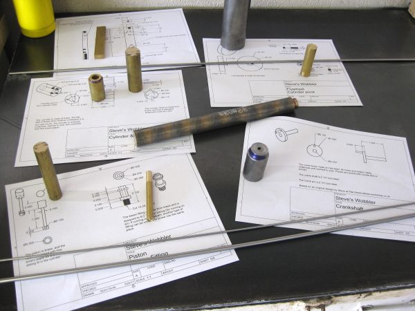
The design of this engine is courtesy of Steve’s Workshop, so I’m calling it Steve’s Wobbler. I started by modeling the engine in Fusion 360 so I could fine tune the timing and valve alignment.
I then used that model and Fusion’s tools to generate drawings in US Imperial units. Steve’s drawings are in metric, if you prefer that. The complete PDF of my drawings is available to Patreon subscribers. If you’re a Patron, check your feed! Okay, let’s make some chips!
The first thing we’ll make is the crank. It’s made of steel. I’m partial to 12L14 free-machining steel for stuff like this. It machines beautifully, especially on smaller lathes with High Speed Steel tooling. The crank is a very straightforward part- just a disk with an off-center hole.
We need a hole in the center for the crankshaft. Center-drill, drill 15/64ths, and then ream to 250 thousandths.
This three-step process for making a hole will be used in most places, because it results in a precisely positioned, precisely dimensioned, very round, and very straight hole. The center drill ensures the hole ends up in the right place. The drill size is always 1/64th less than the final dimension, and the reamer brings us to final dimension. Drills are imprecise hogging tools. Reamers are precise, but can only shave a little bit of material.
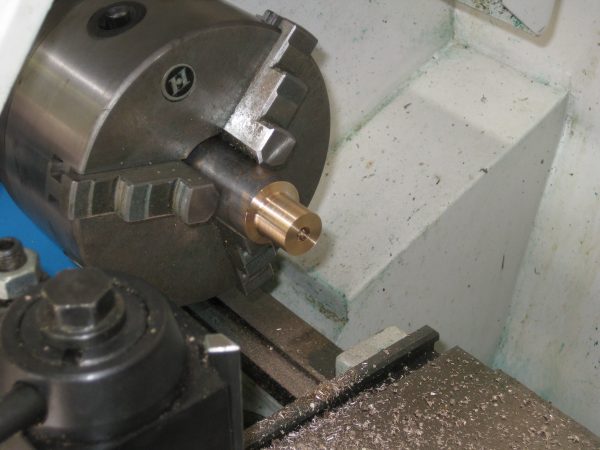
Now we need to face the other side, and get the piece down to final thickness. However the piece is already too thin to hold in the chuck, so we need an arbor. This is easily handled by making the crankshaft next. Cut a piece of 1/4″ tool steel drill rod to length, face both ends, and break the corners.
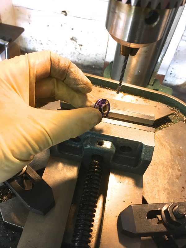
Now we need to drill the eccentric hole. This is what makes it a crank, and not just… a wheel. Lay this out using your fluid and layout tools, according to the drawings. There’s lots of ways to do this, but I used a center-finder to find the center of the whole assembly, and then a compass to mark the arc where the eccentric lies.
We can now make the crank pin using drill rod (refer to the drawings for the dimensions). Simply cut and face to length, and break the edges as usual. It’s a very small part, so it may test your skills with working very close to the chuck.
Next we’ll move on to the main bearing. This is made from bearing bronze, which works really well as a bearing surface against the tool steel crankshaft. Bronze against steel is the magic combination that made the whole industrial world run until ball-bearings came along. Plain bronze bearings are still used in applications where precision is super important. It’s certainly sufficient for our little engine, and easy to make.
The main bearing, as you can see from the drawings, is a more complex part than the crank. It has three different diameters, a precise interior hole, and a bolt circle for mounting to the frame.
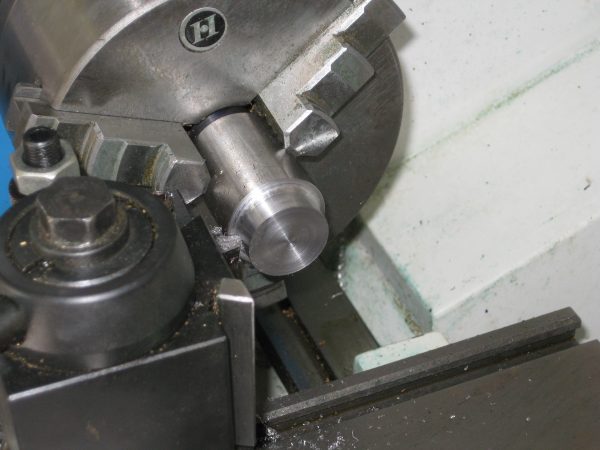
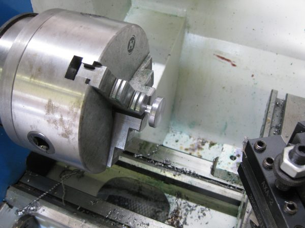
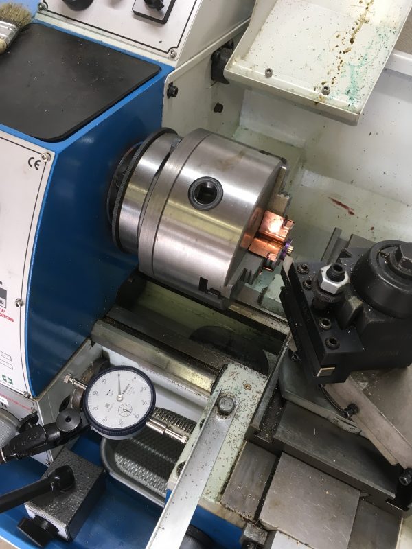
Drill and ream the main bearing to 250 thou for the crankshaft to pass through. Then cut the longer of the two shoulders. This will be important because we need it to grip the part in a moment. The length of this long shoulder is really important. By design, it is slightly longer than the thickness of the frame. The end of the long shoulder forms a bearing surface for the back of the crank, and affects piston alignment (as you’ll see later on). Get this right!
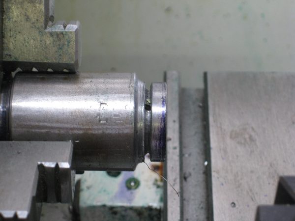
To cut the shorter shoulder, flip the part around in the chuck. Note that we’re technically breaking a cardinal rule of machining here. Three-jaw chucks are precise but they are not repeatable. All three-jaw chucks have some run-out, but when you turn the material down, you cut “past” the runout to a true-rotating center. As long as you don’t move the material relative to the chuck from this point on, all operations will be true and concentric to each other. If you flip the part around like we just did, you lose that. What this means is that our second shoulder will not be perfectly concentric to the center hole. However this is okay, because the first shoulder is the one that holds the crankshaft, so that’s the one that needs to be concentric to the outer surface of the bearing. The small shoulder is just a bushing area for the flywheel.
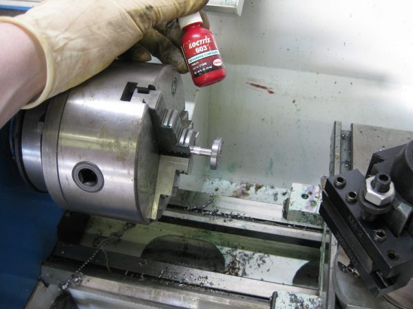
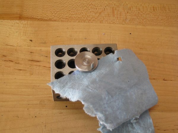
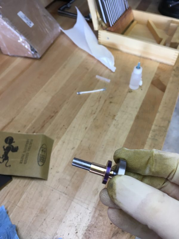
Once the bearing is parted off, it’s a good time to fit it to the crankshaft. It’s important that the crankshaft spin freely. It’s much easier to fit parts to each other as we go along, rather than putting the whole engine together at the end and then wondering why everything is binding up. Debugging a complex mechanism is much harder than fitting one part to another.
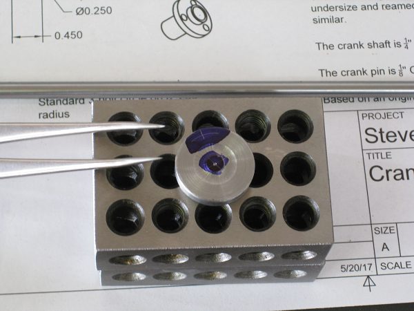
The last thing the bearing needs is the bolt circle which holds it to the frame. Back to the layout tools!
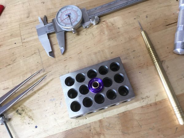
There are a few different ways to tackle this layout. One way is to chuck the part in the lathe, mount a scriber in the tool post and use the cross-slide to measure the right radius. You could also make a bushing to fill the center hole, which would give you a center on which to rest a compass. The way I did it was by locking a caliper to the distance from the hole to the outer edge, and then running that caliper around the outside to scribe the bolt circle.
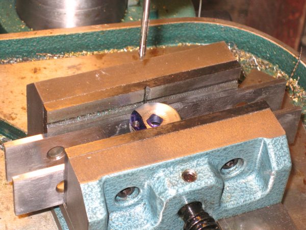
Once the circle is marked, center punch the first hole anywhere on the line. Then using a bolt-circle calculator, set a compass to the straight-line span (or “chord”) between holes. Now you can walk your way around the circle, center punching each hole and using the compass to get to the next one.
A quick note on bolt-circle calculators- most of them are intended for people with digital readouts on milling machines, so they give you X,Y coordinates. That doesn’t do us much good. What we need is one that provides the chord distance between holes so we can walk around with our compass. I haven’t found an online calculator that does this, but there are tables in books for it. Here’s one you can print (PDF warning).
Okay! We now have a fully functional crankshaft and main bearing! It’s a great start for our little steam engine. Next time we’ll get into making the cylinder and piston. So far the precision has been pretty forgivable, but the ante is about to get upped. For the cylinder and piston, our skills will be put to the test. Stay tuned!
For some reason I sense a ‘but…’
Still a good read, even for us not following along in metal.