Wherein we are reminded why dead trees suck.
This article has a companion video for Patrons! Sign up now to watch it!
On the fence about becoming a Patron? Here’s a free sample video!
I’ve often said here on this blog that I am not a woodworker. I don’t particularly enjoy it, largely because the associated tools are all extremely noisy, make incredible messes, and are frequently terrifying. Machine tools, by comparison, are stately and civilized things. Don’t get me wrong, a lathe or mill will happily pulverize your meat into meatloaf if you stop paying attention, but they are not the subject of nightmares and horror films the way table saws are, and I have never seen a human contraption that can make the kind of mess that a router does. The splash-damage range of the dust is measured in meters, because all other units are too small.
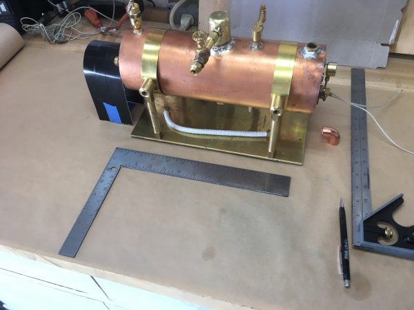
All that said, wood is just the thing in many situations. One of those situations is the base for a model steam engine or boiler. Properly finished, a wooden base is an attractive compliment to all the machined metal, and copes well with the potential onslaught of water. My electric steam boiler is at the point where it needs a base. All the major components are coming together, and they need somewhere to live.
Allow me a quick sidebar on sequencing. Normally here on Blondihacks, I work hard to create an interesting narrative from these projects. That’s usually possible, because I build them start to finish and then move on to the next thing. The electric steam boiler project has been so complex, however, that I’ve had multiple tracks of work running in parallel. One track was constantly getting stuck while I waited for parts or needed to figure out a problem, so I would work on something else in the meantime. While building the base is the next logical thing to show in this series of articles, I can’t avoid showing you pictures of the progress without spoiling some future parts. Consider it a behind-the-scenes sneak peak of upcoming posts in this series. Of course, if you follow me on Instagram or Twitter, you’ve already seen some of this stuff, although without context (which I hope keeps some of the surprise alive). Okay, here we go. Spoilers or not, the blog must go on.
Seeing as how no part of me is a woodworker, I don’t have much good material on my junk pile for this sort of thing. I called a lumber supplier and tried to order some rectangular cellulose bar stock, and they acted like I was crazy. I dunno, what do woodworkers call this stuff? Planchettes? Tree slices? Anyhoo, for nice bases for my steam engines, I usually go to my local woodworking shop, which has a nice off-cuts bin. There’s usually treasure in there, in the form of convenient loins of mahogany, cherry, or other attractive butcher’s cuts of dead trees. No such luck this time- the bin was pretty much empty.
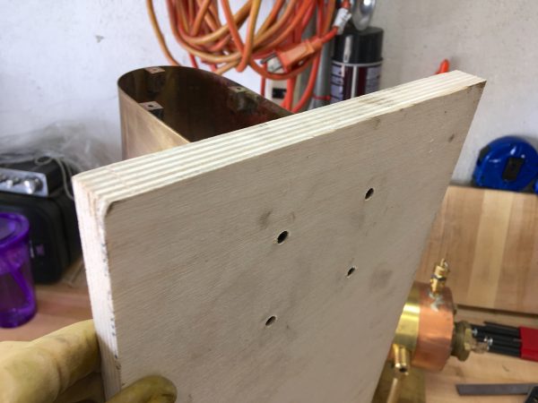
I thought about buying a few board-feet of something nice, but the width I needed meant that no single board would do. I don’t have a jointer or a planer, so gluing up a slab from smaller pieces was mostly a non-starter. I decided to try high-quality plywood instead. They had really nice small pieces of birch, so I grabbed one of those. I hoped that with the right stain and finish, I could make it look like the nice hardwood base I was going for.
With the size determined, I cut the plywood down to size with a circular saw and straight edge. Speaking of nightmare tools, circular saws are high on the list of things that I’m convinced are going to put me in the hospital some day. They sure are versatile though, and it saves me owning a floor-space-eating table saw for the minimal woodworking that I do.
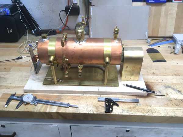
With the major components arranged the way I wanted, I traced the outlines of all the parts so that I could recreate this layout later. I needed everything “fully assembled” to establish the relationships, because (for example) the end of the boiler fits inside the electrical box in a very specific way with little margin for error. However, I needed everything unassembled to mark mounting holes. Tracing outlines is how I reconciled these competing objectives.
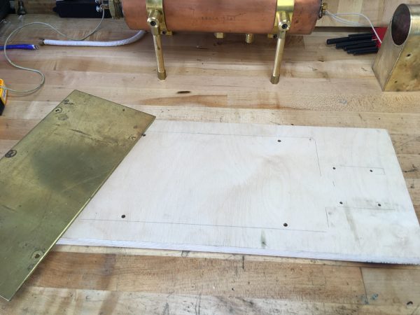
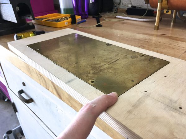
The next logical step was to establish the mounting holes for everything. For the main boiler, this was easy to do, because it has a removable brass base plate with holes in it. This brass plate ties the legs together for stability, and also serves as a heat shield for the wooden base. I decided to use the same screws that mount the legs to this brass plate, and simply run them all the way through the wooden base as well. I lined up the naked brass plate with my traced outlines, and used a transfer punch to mark the holes. These were then drilled through on the drill press, using a backer of scrap wood to prevent tear-out (which plywood loves to do when drilled).
The electrical box was an interesting problem. The mounting points are brass blocks silver-soldered to the inside of the shell, and there’s no way to get a marking pen or transfer punch in there. The box is not exactly square because of my limited sheet metal skills, so measuring wouldn’t work well either. Luckily, there’s a specialty tool that I love which is perfect for this situation- transfer screws.
A transfer screw is a screw which has a point on the end instead of a head. Just behind that point is a hex profile which can be grabbed with a special tool. The screws are hardened like a punch, so you can hammer on them. All you do is thread the correctly-sized transfer screw into the hole you want to transfer, line up the object, and tap it to mark the locations. Since there are no heads on the screws, you then need the special tool to fish them back out of the hole. They are a marvelous tool, and I learned about them from years of watching Mr. Pete on YouTube. His channel will teach you more about shop practices than just about anything else, so go watch! While you’re over there, tell his viewers to come and subscribe to the Blondihacks channel too.
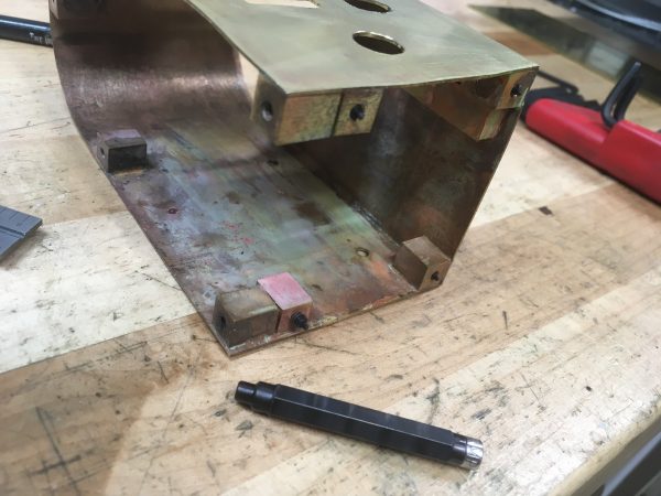
With the transfer screws inserted, I just had to line up the electrical box with the outline I traced earlier, then press down on it. I’m marking holes in wood here, so no hammering is required.
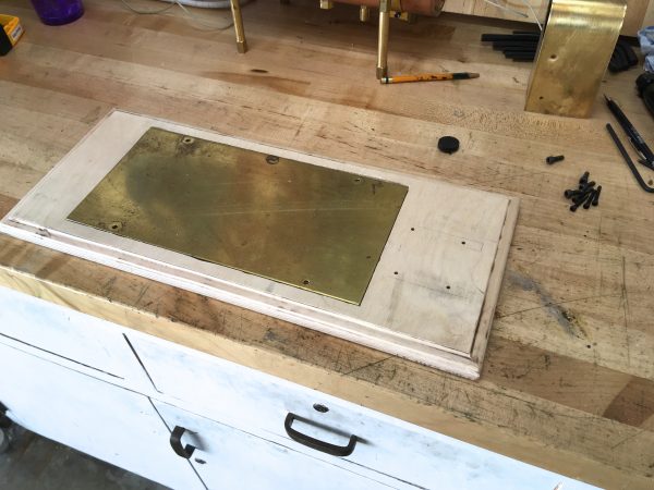
After all the mounting holes were drilled, I also countersunk them with a larger drill bit so the cap screws would be flush with the bottom.
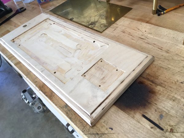
With the basics accomplished, I couldn’t help myself – I needed to get a little fancy. I didn’t love the way the brass plate on the boiler sat on top of the wood. I felt it needed to be inlaid so the top was flush. Time to bust out my least favorite power tool- the router. I am not skilled with this thing, and it has a unique ability to make a colossal mess, no matter what dust remediation methods I try. It is, however, the right tool for this job, so we shall press on. Press On. How about that power switch pun I just made? Did you appreciate it? Good.
The outline that I had traced for aligning the holes was also conveniently the exact area I needed to recess. I used a clamped straight edge with the router to get the edges crisp, though I did still manage to make a couple of mistakes. Routers are difficult beasts to control. This process is tedious because you have to get the distance between the straight edge and the edge of the router bit just right such that it ends up cutting right up to your line, and remains parallel the whole way down. This setup needs to be repeated for each side of the rectangle, and if your desired depth is enough that multiple passes are required, you may have to repeat all this setup work. A router table would be the perfect tool for this, but the tedious-setup method gets the job done.
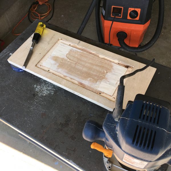
I made a bit of a mess of the center area because of a rookie router mistake. The recessed area is larger than the base plate of the router, so I lost the ability to control depth in the middle. What I should have done was left an island in the middle to support the router, and done everything around it. Then the island could be removed with a chisel. Luckily, it doesn’t matter that the middle is a mess, because the brass plate covers it.
I also brought out a decorative ball-bearing bit and did a filet on the edges. This fancy look is a bit of an odd thing to do to plywood, since you can really see that it’s plywood around the decorative edge, but I hoped it would look nice after staining.
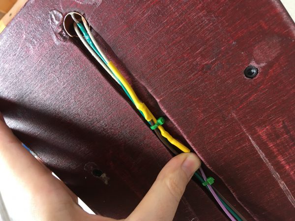
The next task was to handle the wiring at the far end. By necessity, the thermoswitch is in the opposite boiler head from the heating element, where all the electrical stuff is. That means we need to get those wires from one end of the boiler to the other. I want to hide the wires, so I decided to run them inside a copper pipe, then through a channel under the base. I carefully lined up this pipe, and marked the location on the base for drilling. The pipe is a press-fit in the wood, so I drilled it slightly undersize and opened it up to fit perfectly, using a round file.
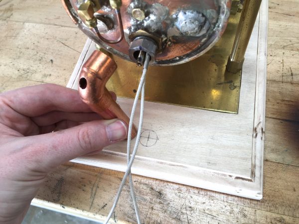
There’s a tricky order-of-operations to make this all work. The vertical pipe slides in from above, further than needed, then the wires are fed through the elbow and down the pipe, then the pipe is slid back up into the elbow. It took some gray matter to figure out how to make this happen such that it was all still removable for servicing!
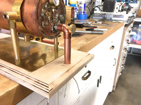
You might have noticed that I completely glossed over a pretty interesting part there- what’s that whole deal with the copper elbow and the fancypants brass knob running through it?! Well I’m glad you interrobanged, because I have a video explaining that whole situation! As you may know, I’m now producing private video content for my Patreon supporters. However, to give everyone else a sample of what you’re missing, here’s a public video of the making of this feature. If you like it, subscribe on YouTube and pledge on Patreon to catch all the rest!
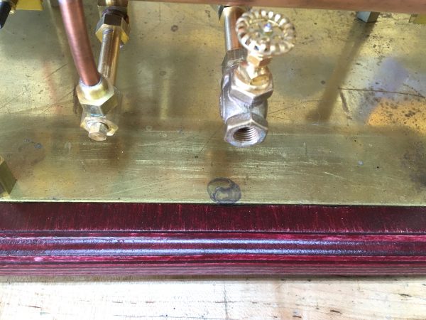
Okay, moving right along. At this point, I was very happy with the inlaid brass plate, but now I had a problem. The electrical box had been sized to line up with the end of the boiler before I recessed the base plate. Whoops. I couldn’t rework the electrical box without messing up the carefully planned internal dimensions (more on that in a later post), so what to do?
While I had the router out, I also cut a channel in the bottom of the base plate to run the thermoswitch wires from the far end back to the electrical box. I didn’t show that in photos because I did it super half-assed. At this point in the day I never wanted to see the router again, so I regret nothing.
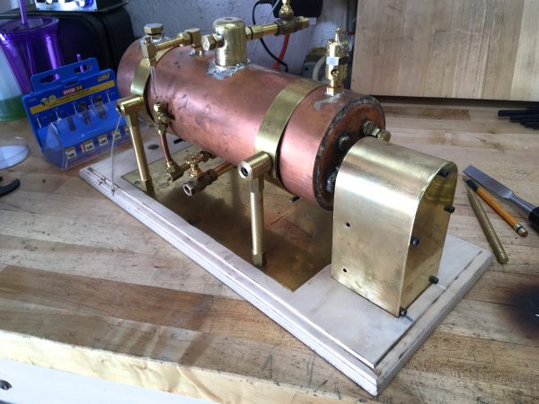
After some light sanding to tidy up all the edges and corners, it was time for finishing. My other steam projects are all red-toned woods like mahogany or cherry, and I wanted the boiler to kinda match. This birch plywood was not going to do. I opted to use a colored stain, then coat it with polyurethane for protection from water.
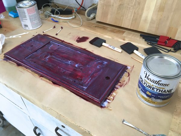
I did two coats of polyurethane with a light sanding in between, and for my first-ever wood finishing project, I’m pretty happy with the result. It’s very smooth to the touch, and water beads right off it.
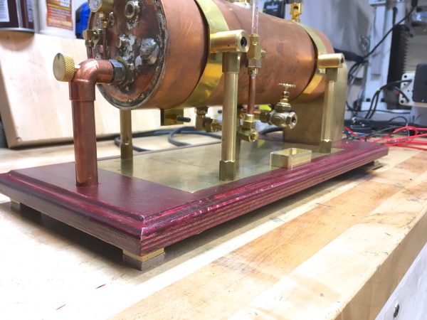
The last thing I wanted were feet for the underside. Steam engines and boilers are a wet environment. Things are going to get damp, despite best efforts. Valves drip, steam condenses, blowdowns happen, and so on. If you’re working with steam, water is a thing that will be everywhere. If water gets down around the base, that high-voltage wiring underneath will be sitting in water. I’m not crazy about that notion, so I want to lift the base off the deck.
I decided to make some feet out of scrap brass stock with felt furniture pads on the bottom. Good news Patreon Patrons- I made a video of the making of these feet just for you! Check your Patreon feeds and email boxes for that. Yes, that’s TWO videos for this one post! The public sampler and a second one just for you Patrons because I heart you so very much.
That’s all for the base! I believe the last thing to do is finalize the electrical, so stay tuned for that! This epic project is very nearly complete!
Woodworker here! It’s fun to see you dabbling in my hobby, even if it isn’t your first choice.
“A router table would be the perfect tool for this, but the tedious-setup method gets the job done.”
I do have a router table, and I think I’d still do it how you did it. Partly because stopped cuts (ones that aren’t all the way from one end of the work piece to the other — is that the same terminology in machining? I’m not sure) are a bit of a pain on the router table. But mostly because to do the cut, you’d be flying blind — the cut would be happening with the work piece face down, and you wouldn’t be able to see if something was going wrong. Some people might choose a table, but I’d probably grab the plunge router and do what you did.
I can’t tell you how many times I’ve forgotten to leave an island, and had the router tip and make a deeper gouge than I meant to make. Fortunately, it’s usually somewhere that is getting covered up anyway, just like with your project here. Perhaps someday I will stop needing to relearn this lesson.
“This fancy look is a bit of an odd thing to do to plywood, since you can really see that it’s plywood around the decorative edge, but I hoped it would look nice after staining.”
Some people do that on purpose because they like the look! There are wood turners who glue up plywood and then turn them on a lathe, and it reveals interesting patterns of the plies on the final bowl or vase or whatever. Anyway I think it’s kinda cool looking, especially because of how infrequently it is done.
I get how it always feels like a compromise when it wasn’t the first choice, though. Still, you did a nice job. You didn’t rip up the birch veneer on the plywood, which is something that has happened to me plenty of times. And after staining, what you can see of the plywood appears to look a lot like edge grain would have looked had it been made out of hardwood.
Oh, you’re one of THOSE. 😉 Thanks for the input! I see what you’re saying about the router table. The entry and exit points would be really hard to get right. Regarding plywood, yah, I’ve seen how it’s popular to do interesting things with exposing the end grain in patterns and such. Seems to be especially prominent among the “modern” furniture crowd. It’s all concrete, white melamine, and plywood end-grain over there. 🙂 I wanted to avoid accidentally creating a modern look with blonde plywood, since that feels at odds with a brass and copper boiler. Now that I think about it, it would be fun to make a modern looking steam setup. Maybe use all stainless steel.
Anyways, great to know I’m not alone with stranding my router at sea, no islands in sight.
If you absolutely have to do stopped cuts on a router, it’s worthwhile to calculate offsets and clamp stops to the table, so you run the workpiece until it hits a stop, then lift it off, and spin it 180 and do it again.
But man, doing these exact same operations on a piece of wood clamped in a vise on a milling machine is sure pleasant. I own a router and a wood lathe, but I do 90% of my woodworking on the mill and metal lathe.
Aside about damage: wood is somewhat similar in consistency to skin, so tooling designed to remove lots of wood does the same to skin. Metalworking tooling usually has much lower chip loading, so you remove a lot less skin per unit time.
I considered doing this inlay cut on the mill, honestly, because in one sense it seems like the perfect tool for the job. However, I’m pretty hesitant to work wood on the machine tools because of the problem of sawdust getting in everywhere and messing with the oil and such. What tooling do you use? Router bits in the mill, or normal end mills? What spindle speed?
Normal end mills (two flute), as fast as the mill can go (in my case, that’s about 9000 rpm.) I got some loc-line 3/4″ segmented tubing and stuck two runs onto an adapter for my shopvac that’s bolted to the bench beside the mill, so I can stick the shopvac nozzle onto it, and put the termini of the loc-lines on either side of the bit. That catches about 90% of the chips, whether metal or wood. (For endmills. It’s grossly inadequate for flycutting.)
Ditto. We have a small benchtop mill in the shop. It’s perfect for inlay cuts and pockets. FWIW, I get better results with 4 (or even 6, if I can find one the right size that isn’t too dull) flute end mills. No (manual) mill in the world has the spindle speed to use a router bit to good effect. You get a lot of rubbing, especially on hardwoods.
I actually prefer a wood lathe for circular section wood work. A metal lathe is more accurate, but you generally aren’t trying to hold a couple thou on a stair rail balluster, so a wood lathe is faster. I mark the blank where the diameter changes, set up however many outside calipers are necessary to get it done, then use a parting tool to cut the marked lines to diameter. Once that’s done, break out the gouge and turn it “by eye” in smooth curves to the parting tool cuts.
And one exception: if you want spiral climbing cuts, nothing beats a 4-axis CNC machine, whether mill or router.
As luck would have it, I chance to be a master craftsman in wood, presently employed as a cabinetmaker. You’re right about the router, but we woody types don’t mind. If your bench is knee deep in shavings, nobody can accuse you of not working 🙂 You’re also right about the table saw, but it can be done safely. I’ve got 50 years in… and 10 fingers. A handheld circular saw scares me more, actually; albeit I also have a regrettable amount of experience with one. I often clamp a straightedge to the workpiece to get a clean cut, just as you did. (Actually, I have a set of quick-grip clamps for the purpose, featuring both a nice edge to run the base plate of the saw on, as well as an inlaid rule to gauge non-through cuts; but you won’t use them enough to make the purchase worth while.) The easy way to find the set-off is to change to the blade you intend to use, clamp a straightedge to a scrap, make a short cut, and measure out from the straightedge. You’ll get it right every time. I saw a combination square on your bench; that’s a good tool to use for the set-off.
Good choice on your material as well. From the one clear edge shot, it looks like a piece of 19mm Baltic Birch. The stuff sands sweet and smooth, as well as takes finish beautifully, as you have discovered. Nice material to work with, even if most of my personal work is with natural hardwoods rather than engineered materials. I laughed out loud at the “rectangular cellulose bar stock” crack. Be warned, I shall use it at work as soon as I can.
Good job on the base. It looks neat and well done.
Thanks for sharing! Clearly I should hit up my readers for woodworking advice in the future. I’m glad someone got the “cellulose bar stock” joke. I wasn’t sure if that one was too obscure. 😀