Finally we can make flat things.
The lathe is called the King of Machine Tools for very good reason. There’s arguably nothing you can’t make with it. Other machine tools mainly serve as ways to make it quicker and easier to do things lathes can do. There are a few exceptions, but you have to work pretty hard to need an operation that can’t at least theoretically be done on a lathe with a sufficiently elaborate setup.
It turns out that one of those commonly-needed elaborate setups is flattening things. On a lathe, you typically do this with the somewhat-ironically-named “milling attachment”. This generally takes the form of a vise with a vertical slide attached to the cross slide on the lathe. That gives you the third dimension that the lathe is missing, thus giving you two dimensions of travel orthogonal to the spindle and one dimension of travel parallel to it. Milling attachment setup is time-consuming enough (and sufficiently lacking in rigidity) that it’s worth having a dedicated machine just for this. Enter the vertical mill.
A vertical mill is essentially a lathe stood on end with a large milling attachment permanently affixed. It’s arguably the current “standard” for multi-point machine tools (in contrast to the single-point cutting tools like lathes and shapers). The vertical mill is far from the first attempt to optimize the flattening operation on a lathe. Flat surfaces and features were previously made on things like shapers and metal planers. A shaper is particularly useful, because it’s extremely adaptable to different operations, can reach inside parts in ways other tools can’t, and can use the same tool bits as the lathe (perhaps with a slightly different grind). However, as the old machinist’s joke goes, “you can make anything with a shaper except money”. Shapers are versatile, but they are not fast. Vertical mills are fast, so as soon as metallurgy and manufacturing advanced to the point of making complex tooling like end-mills practical, milling machines came to dominate.
When most people think “mill”, they think “J-head Bridgeport”, unless they are not a machining nerd and thus think “making flour from grain”. Bridgeports are popular, well-respected, and all the cool kids seem to have one, but they are far from the only choice. The Wells Index machines, for example, are an underdog that real machinists know and love. For those of us without a lot of shop square footage, a bench-top mill is a great choice. The main difference with a typical bench top mill is that there is no “knee”. A knee-mill is the most well-regarded design, and dominates among large machines. The knee is what provides most of the vertical table movement (in addition to the quill), and it’s a very rigid way to do so. It also consumes a lot of space, so bench-top machines trade the knee for moving the head itself up and down on a column. So-called column mills are less rigid, but compact and versatile for their size.
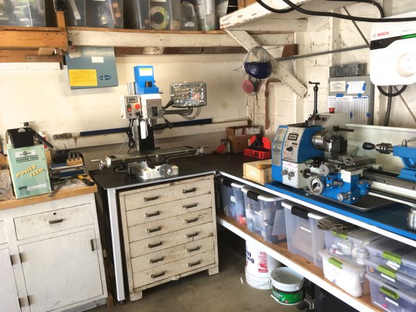
Nowadays, for bench top mills, you’re going to be talking modern Asian-made clones like Grizzly and Harbor Freight. While there were bench-top mills back in the day, they were not common and are now hard to find. After a fair amount of research, I landed on the Precision Matthews PM-25MV. Not least because I’ve been quite impressed by the build quality on my Precision Matthews 1022V lathe. I’ll spoil it now and declare I’m extremely happy with the PM-25. The build quality, rigidity, motor, and bearings all seem excellent. Let’s dive into how mine is set up.
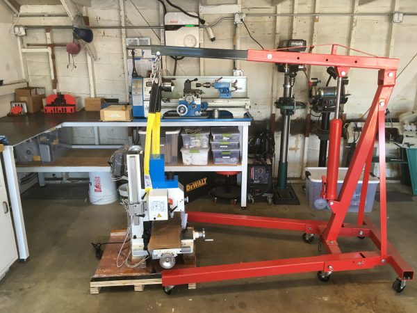
First things first, we need space! I had built an extension to my bench with this in mind, but there’s a catch- an overhead shelf. While the shelf will clear the mill, I need a lot more vertical space in order to get the crane in there to place the mill on the bench. Dilemma!
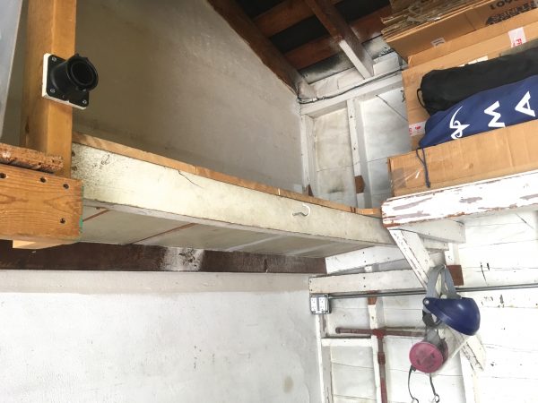
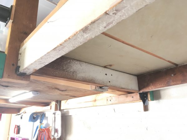
After some pondering, it occurred to me that the shelf is attached to the wall on one end, which makes it a great candidate for hinging upwards. I had built it years ago as a standalone frame to fill that otherwise wasted corner, so hinging was an easy decision. By being hinged, I can move it out of the way for the rare times I need the headroom, and still take advantage of the storage 99.9% of the time.
After trimming a few areas of the shelving boards to add clearance for the soon-to-be-moving structure, it was time to take it down.
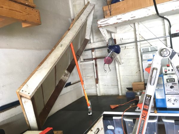
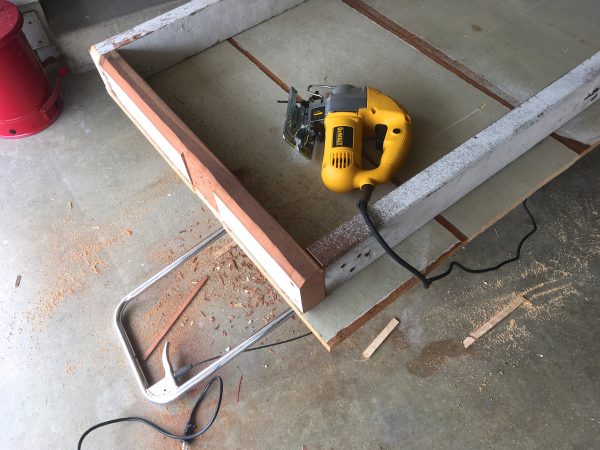
With the shelf out, I need to modify it for more clearance. A moving thing requires a lot more personal space than a stationary thing. In particular, the end opposite the hinges will describe an arc as it moves, and any material within that arc needs to no longer exist. Otherwise, the shelf will not be able to swing up.
Okay we’re ready to attach hinges, right?
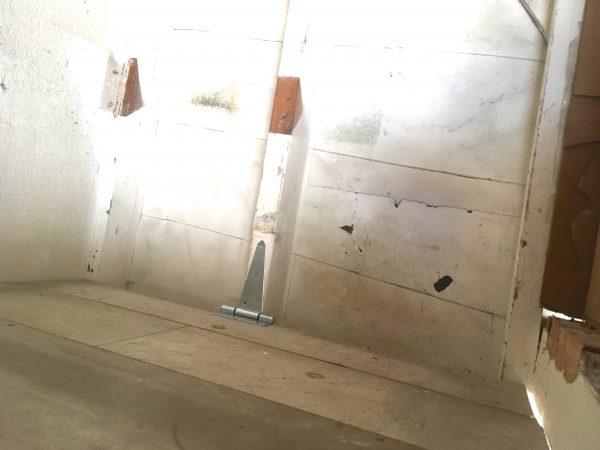
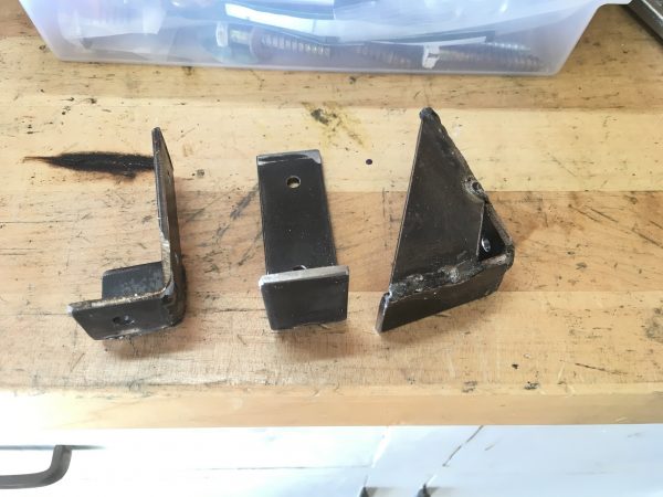
In my experience, virtually all problems in life can be solved with sufficient application of steel. This is no different.
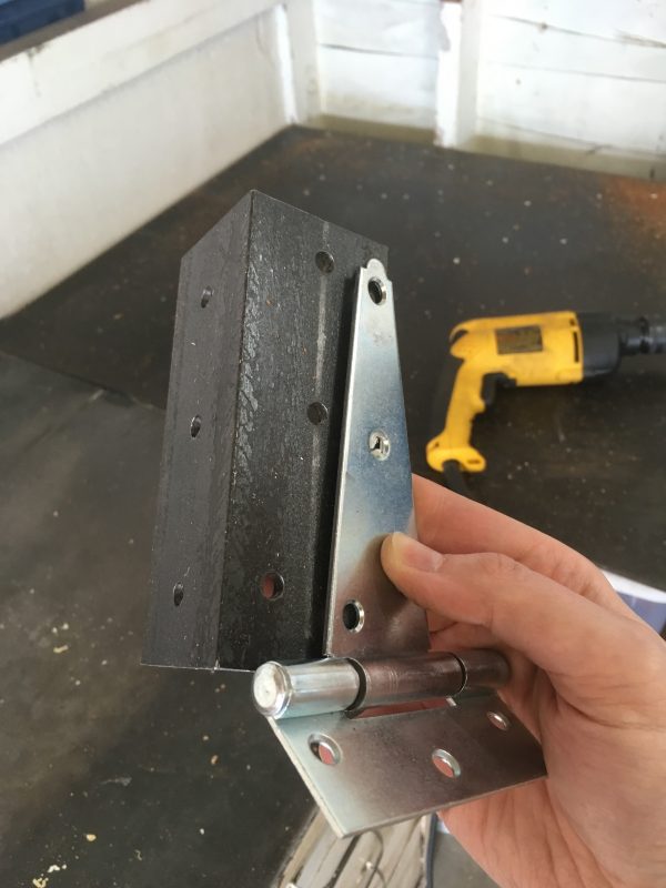
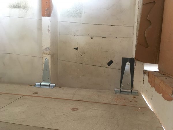
For this hinging idea to be complete, the end opposite the hinges needs to be supported. Once again, steel to the rescue.
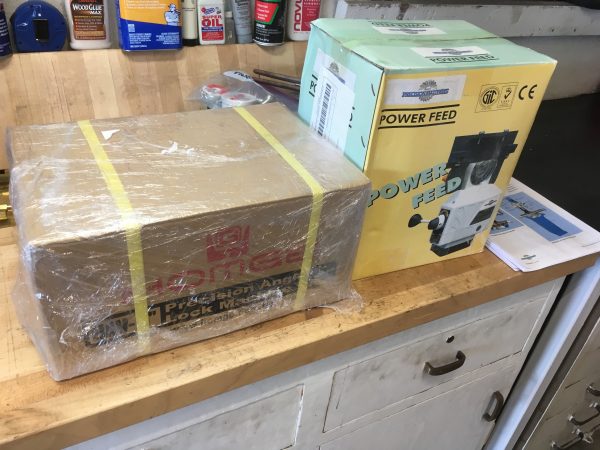
Alright alright- enough futzing around with shelving. Get to the mill, already! Let’s do a bit of an “unboxing” blog.
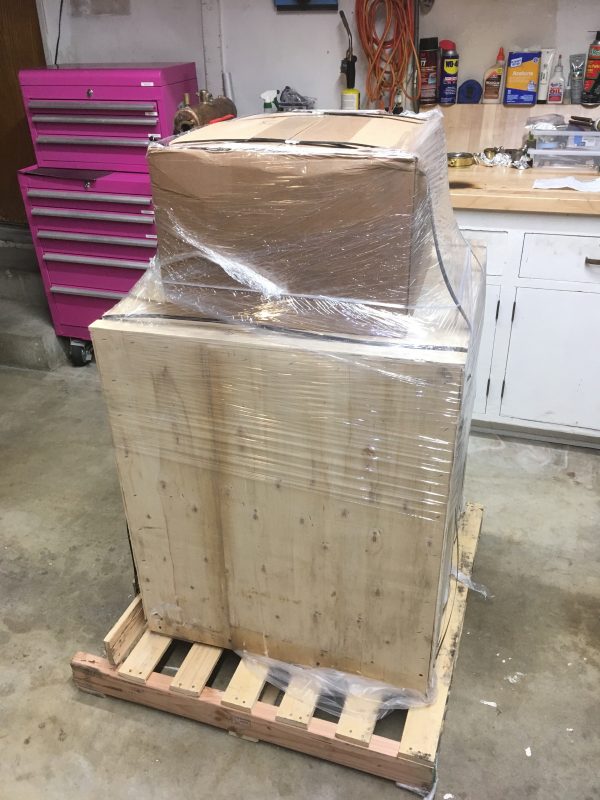
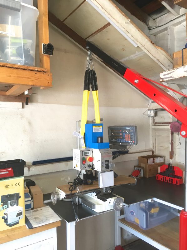
The next step is to get it rigged for lifting. While this is a small bench machine, it’s still about 300lbs. It needs to be lifted with proper tools and safety measures. The manual describes the proper lifting point.
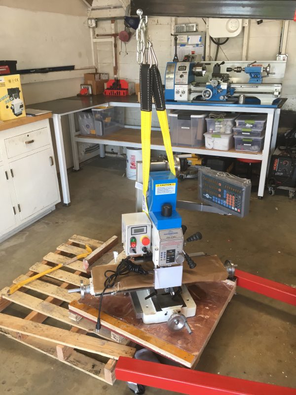
The standard lifting safety rules apply here. Always use a proper lifting sling, not random ratchet straps or whatever ropes you have lying around. Lifting slings resist shearing, distribute load, and are reinforced in the hook areas. Make sure nothing is under the sling that can be crushed. In this case, we need to mind the electrical box and the DRO arm.
When the load is up, keep all meat-based things out from under it, control momentum, plan your moves, and don’t do anything suddenly. Never do anything in a hurry.
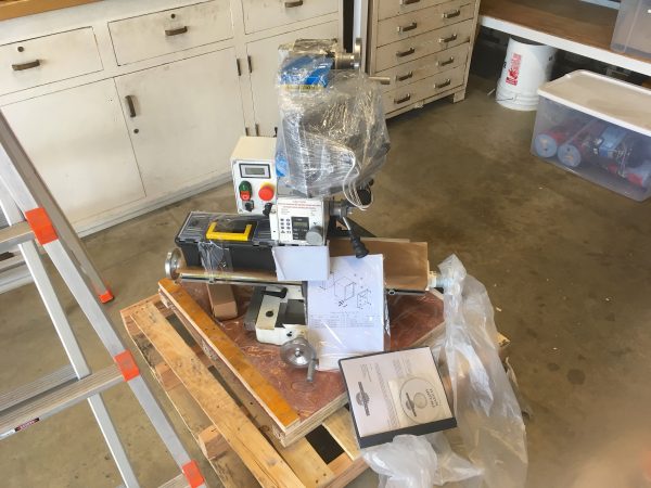
You may notice that the chip tray is not shown in these photos. Truth be told, I thought it didn’t come with one. I certainly expected one, but when it wasn’t in the crate, I figured it was part of the optional stand, and so I didn’t get one. No big deal, I figured. Turns out, which I learned while dismantling the crate for disposal, that the chip tray was bolted to the underside of the lid of the crate. Whoops! Just as well, I actually prefer the mill without a chip tray. Mills throw chips like crazy (much more than lathes) so a chip tray is largely decorative in any case. A flat bench under the mill is easier to clean. I may install it later if I start running flood coolant, as the tray would be helpful for catching that.
At this point, I needed to get the mill positioned where I wanted on the bench. I wanted it as far back as possible while still having room for the front crank to be comfortable to use. Pushing it back reduces the chances of bumping into the crank handle and snagging it. The trick to maneuvering the mill into place is to leave the crane attached, with some tension on the sling. That takes most of the weight off it, so you can easily slide it around as needed.
After marking the holes, the mill then has to be lifted off the bench and put back on the floor again. This may seem silly, since you could just measure the mounting holes or make a template of them. However, the only way to be sure the crank handles are exactly in the right place is to put the real mill where you think you want it. It’s also important that the table have full travel in both directions, and that doing so is comfortable from the working position. I really wanted to get all of this right, so I did the extra work of physically prototyping the mill’s location.
Now we just need to lift it back into place, and…
Now it’s time for a little tune-up and customization. No machine tool is perfect, and anytime you ship something heavy across the country, damage is fairly inevitable. This machine is terrific, but it did arrive with a few issues to sort out.
The first issue was the DRO mounting.
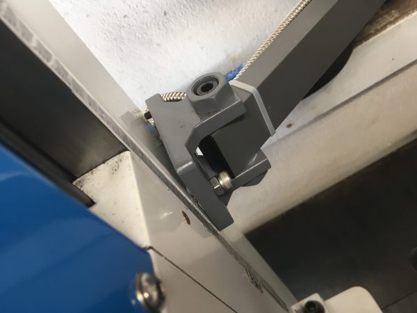
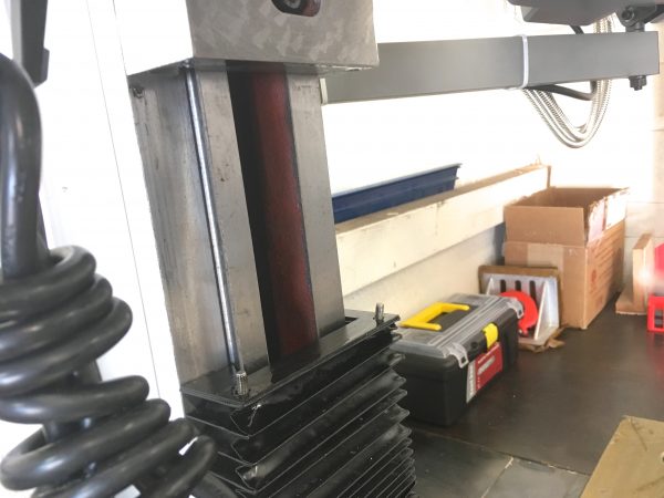
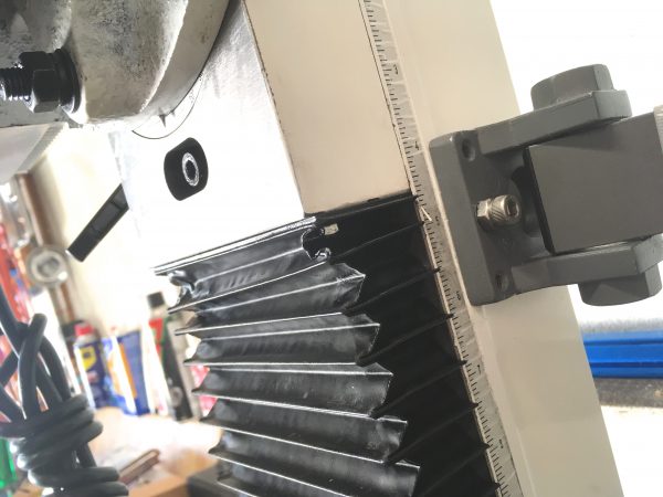
The other problem area was the column ways cover. It’s a typical accordion-fold cover that slides on the ways.
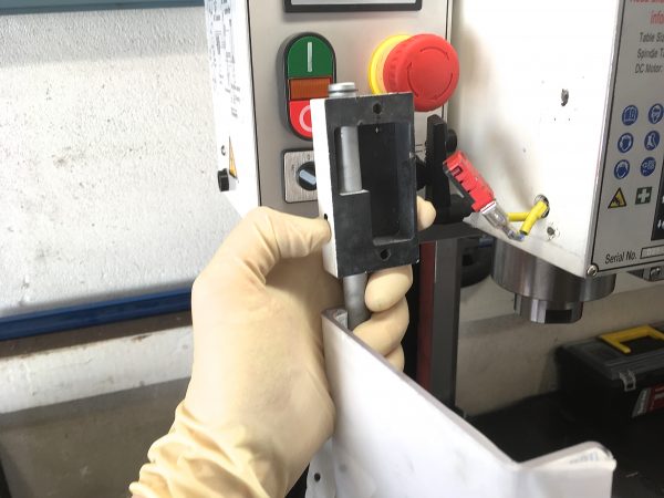
With the shipping problems sorted, there was one customization I wanted to do right off the bat. The mill comes with a safety shield that opens and closes around the spindle. It’s interlocked, so the mill won’t run with it open. I’m not generally a fan of circumventing safety equipment. However, it was immediately obvious that this thing was going to be colossally in the way, and needed to go. Removing the shield is easy, but we need to defeat the interlock so the mill will run without the cover.
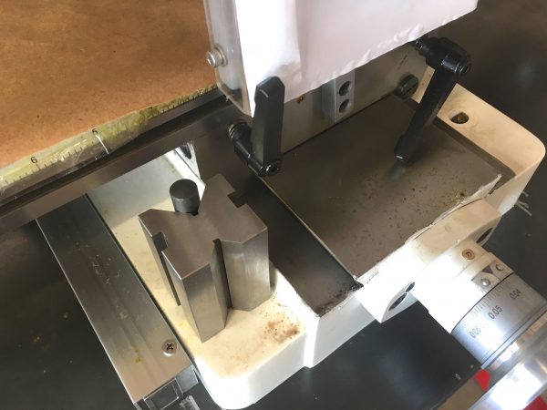
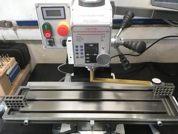
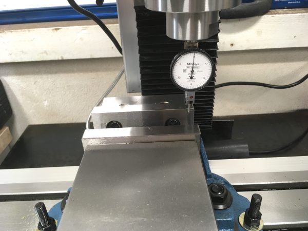
The machine looks ready to go now, but before we can make chips, we need to tram the head. It will be close from the factory, but “close” is only good enough for woodworkers. You can buy fancy tramming tools, or you can take ten minutes and make one from some scrap. Guess which option I took?
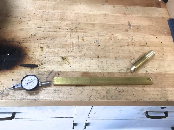
All you need is some sort of arm that will hold a dial test indicator at some distance away from the spindle. The longer the arm, the more precise your tram will be, but the more time you’ll spend doing it. Precision always costs time (which is why it also costs money, by the transitive property), so it’s up to you to find that balance. My simple brass tramming arm is a piece of round stock turned to fit in the spindle on one end, and is press-fit into some bar stock on the other. The bar stock has a 250 thou reamed hole for a perfect snug fit on the dial-indicator’s post.
Tramming is an exercise in patience, but it isn’t difficult. You loosen the head-tilt bolts just enough that it can be moved by a tap from a soft mallet. Then you swing the arm back and forth and measure the difference in height at the ends of the table. Make small movements until you get them the same.
With the tedium of tramming out of the way, we’re ready to make chips, right? Right? Not so fast. A vise is a supremely convenient way to hold work on the mill, and 90% of what we do will involve a vise. However, when you bolt a vise to the table, you’re introducing a whole new source of error. If it’s a pivoting or swiveling vise, you could be introducing multiple new sources of error. We minimize this by “indicating” the vise. This means adjusting it until it’s as square as we can get it, then bolting it down.
No head tram is perfect and no vise is perfectly indicated (or itself perfectly square). All these little sources of error add up and appear in your final part. The best we can do is minimize them all.
With our head trammed and the vise indicated, we’re finally ready to make some noise.
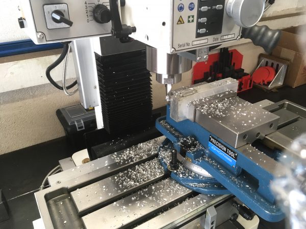
Spending some time on scrap with the machine is time well-spent. Learn the personality of the machine! For example, the manual says this mill’s worm-drive fine down-feed on the quill has zero backlash, but I found that to be incorrect. I found it has about four ten-thousandths of backlash in it, so I can hit dimensions much easier by feeding it down past where I want, then winding it back up to the right value on the quill DRO (thus removing backlash in the direction of tool pressure). Learn how to love your machine, and it will return the favor.
There you have it- a fancy new tool in the Blondihacks shop, and I really could not be happier about it. I hope you enjoyed reading about the basic process of installing and setting up a new mill. Stay tuned, because we’ll be making lots of stuff on this machine in the very near future.
Very nice! I’m envious.
It’s pretty obvious that you are not going to be making any money with a mill either. You sure love to knock woodworking, but that’s because you can afford metal and and all the equipment to work it. I made every piece of wood furniture in the room where I’m typing this now, including the desk and the computer case, and yet all the wood to build it all, together with every woodworking tool I own, had cost me less than you paid just for this one mill. I don’t begrudge you your entertainment, of course; what good is having money if you can’t have fun with it? Who doesn’t like cool expensive toys? I would merely point out that woodworking is a considerably more useful skill for most people and you could reap greater benefits from doing more of it instead of complaining about it.
My sense of humor seems to have offended you Mike, and for that I’m sorry.
> Pushing it back reduces the chances of bumping into the crank handle and snagging it.
And for when you drop something, bend down to pick it up, and on standing up hit the handle with your head.
Nice new addition to the shop!
Quinn, nice job on the setup, your machine shop is growing by leaps and bounds!
Did you get the option where you can drive the sucker with a CNC system as well? Or is the panel to the right (where you talked about the crappy arm mount I think) is just there for digital readouts?
I’m curious what you’re criteria were for the unit and if CNC was anywhere in the list?
The PM25 is a good candidate for CNC conversion, though there isn’t an official option for that from Precision Mathews. My understanding is that there are 3rd party kits for it, but I haven’t looked into their feasibility. I suspect they are like low-cost 3D printers: they work, but are a constant project to keep them that way. My machine tools are there to do work, not be projects unto themselves (mostly 🙂 )
The panel you’re seeing is a DRO, which is exceptionally useful for mills. A DRO allows you to ignore backlash in the hand wheels, and also does math for you for laying out bolt circles, finding centers, things like that. They also have programs for milling arcs, tracking waypoints, marking dimensions, and so on. People use them on lathes as well, but for a mill, the ROI of a DRO is huge.
I didn’t consider CNC, mainly due to cost. For an off-the-shelf robust CNC solution, you’re looking at 3x the cost just to get in the door. That gets you into the range of a low-end Tormach, which is built on steppers rather than proper servos (not that they aren’t good machines, but they are criticized widely for this). A Tormach is a huge investment in money and space, and the tooling for them is also very expensive. The other options are those CNC routers that people do some light milling with, but those are much too lightweight for much real machining work. Meanwhile, a stout robust manual mill that can do real work and uses inexpensive standard tooling is quite inexpensive now.
In my opinion, the main advantage of CNC is for production. They are great if you need to make ten of something. If you’re making one of something, the advantage is much less compared to the cost, and you’re also taking a lot of the fun out of the process. Machining manually is fun and kinda the whole point! CNC turns everything into a software exercise, and I spend too much time on computers as it is. When I’m in the shop, I want to be making things with my hands!
That doesn’t rule out CNC conversation later, but I’m very much enjoying manual machining right now.
As for why I chose the machine I did, I basically got the biggest one that would fit in my space, and the most I could afford. 🙂 Like with lathes, bigger is generally better, and you generally get what you pay for.
I run my mill manual about 2/3 of the time, but, wowie, automated drilling is sweet. Finally, my bolt-together parts are perfect. That’s especially nice for things like steam chests, where there’s a cylinder, the valve plate, the chest body, and the chest cover, all of which need four to twelve holes perfectly lined up.
That does sound nice! My bolt circles always end up close-but-not-quite. 🙂
i totally get the manual aspect of using tools vs a cnc machine of sorts. of course in my lab the closest thing i got to a lathe is chucking up a peice of metal in a hand drill and shaping it with files and such and the closes thing i got to a cnc machine is a $400 3d printer with a tiny build area (and i think its robust enough to convert to a pcb mill). like i had to make a small pcb recently and while im pretty comfortable with doing toner transfer, i wasnt about to waste an entire $2 blue sheet for a one inch pcb. so i ended up cutting the traces with a box cutter and a dremel. i was actually rather pleased with the result.
A trick I often use to avoid wasting blue sheet is to print on plain paper first, then cut out the the same size patch out of blue sheet, painter’s tape it to the plain paper and feed it back into the printer. Use your printer’s manual feed an mark a corner of the page so you know you’re feeding it the same orientation both times.
A small quibble WRT your tramming arm:
All cantilevered beams flex proportionally to the cube of the distance between the supported end and the load. Their resistance to bending is proportional to the cube of their vertical thickness.
For a brass arm of the length and thickness shown above, surprisingly little end force will produce 0.001″ of deflection. You might want to check the repeatability of the measurement by putting a finger on the end of the beam three or four times to see how well it springs back to position.
If there’s enough error to be a problem, turning the bar on its edge and brazing a rod along the hypotenuse of the triangle will make the arm much stiffer.
Rigidity doesn’t matter a whole lot in this measurement, because you’re just comparing one side to the other. There may some lowered repeatability due to spring as you allude to, but when tramming you go back and forth about 50 times, so it averages out anyway.