Because everything is better with bluetooth.
This article has two companion videos! There’s an overview on the Blondihacks YouTube channel, and an insider look at resin casting just for Patrons. Sign up now to see it!
I normally have a pretty strict hipster-punching policy, but I’m about to do the most hipster thing I have ever done. Bear with me.
Every year, I attend an Apple-II-centric retrocomputing event called KansasFest. One of the defining activities of this event is a sort of swap-meet/community-redistribution thing called the Garage Giveaway. It started as a couple of collectors donating their very large stashes of Apple II gear to the community that will appreciate it, but has since morphed into a more general “free retro stuff” table. A couple of years ago, something amazing was sitting there, and the moment I laid eyes on it, I knew I had to do something with it.
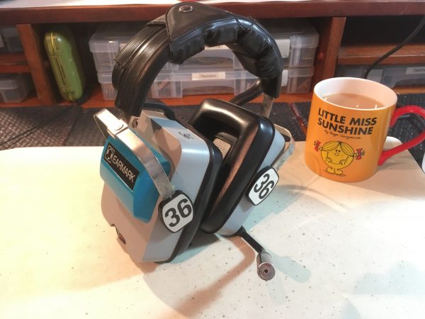
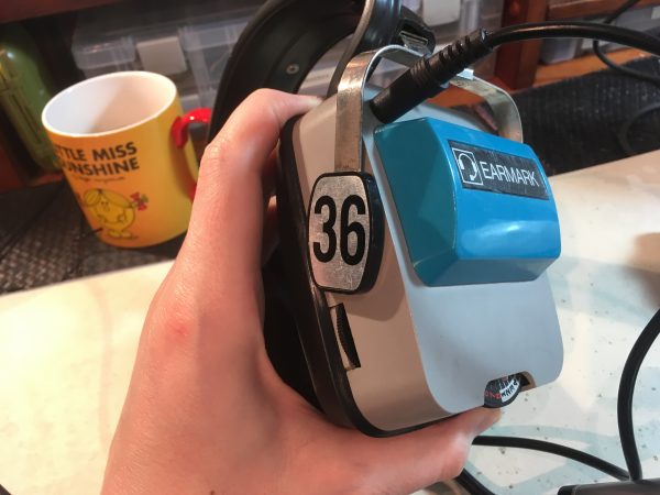
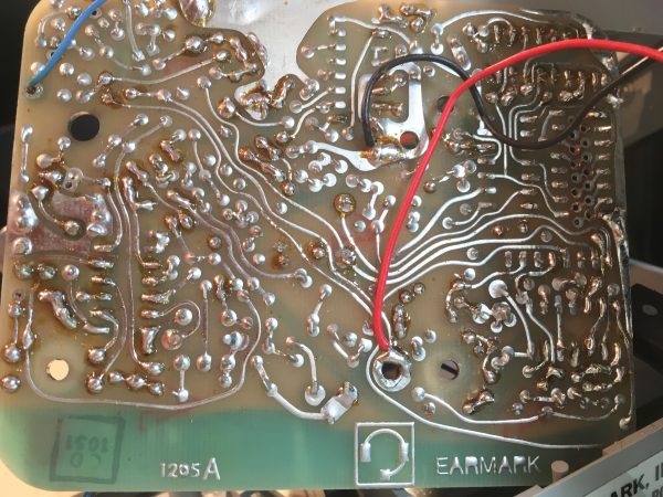
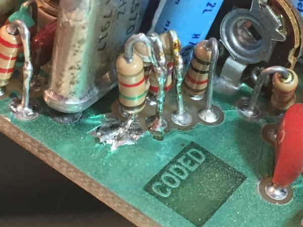
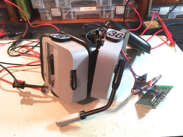
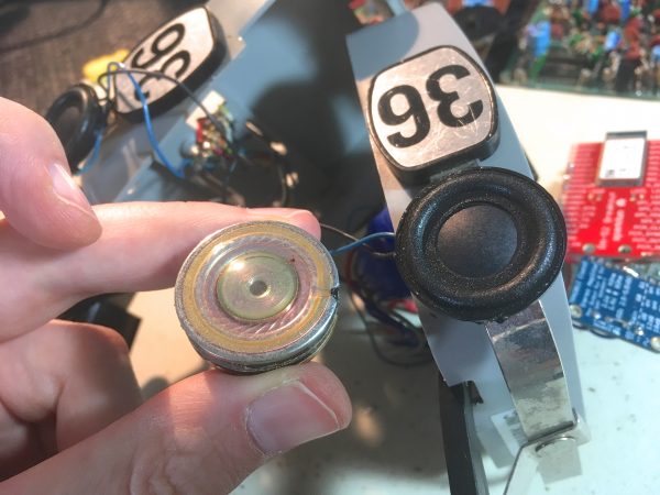
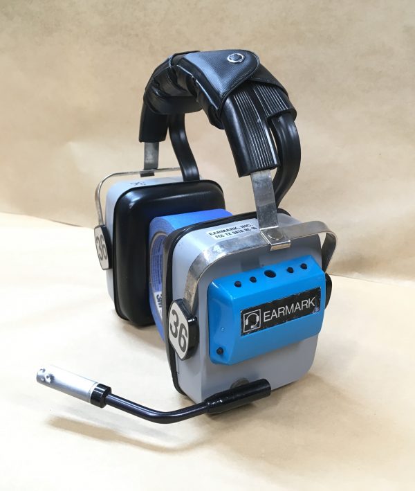
The Earmark company still exists, but I couldn’t find anything that would suggest what model I have or what year it is from. Earmark makes headsets for air traffic control, construction, mining, that sort of thing. This unit appears to be part of a larger “closed circuit” system, because the number 36 is marked on strategic components, as we’ll see. Let’s dig into this thing and see what treasures await us.
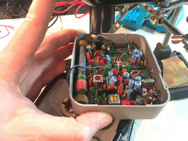
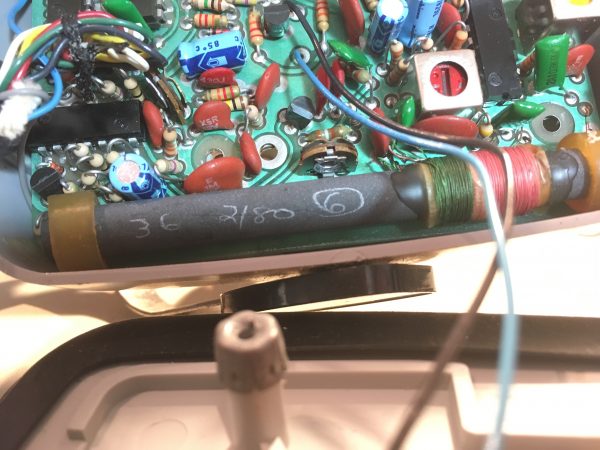
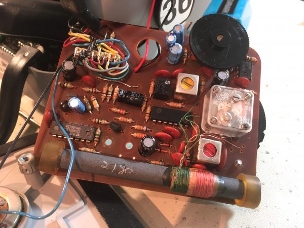
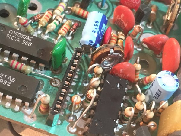
In that last photo, you can see the crystal can for the radio there. The can is marked 154.5700 MHz, which shoots down my “2180” theory. In hindsight, that makes perfect sense. 154.57 is the “A” band in FCC nomenclature, which is VHF, commonly used in aircraft (and perhaps air traffic control?).
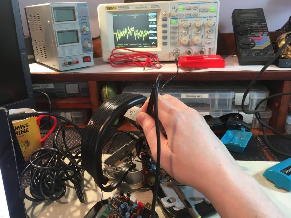
I gave the headset a quick test, but couldn’t get any life out of it. The functional condition is unknown, nor is it known what sort of base station would be needed to get the radios to perform their intended duty. However, I wanted to do something with it.
The obvious thing is to convert it to a bluetooth headset for modern use, right? As I previously warned, converting a 1980s-era air traffic control headset into bluetooth headphones is probably the most hipster thing possible. Normally, I don’t allow projects like this around here. But look at these headphones. They are amazing and I love them and I want to use them so I am going to make them bluetooth also shut up. If I have to punch myself as result of now being a hipster tool, so be it. I set out to do this in a non-destructive way that was reversible, at the very least. I wanted to respect the original hardware as much as possible.
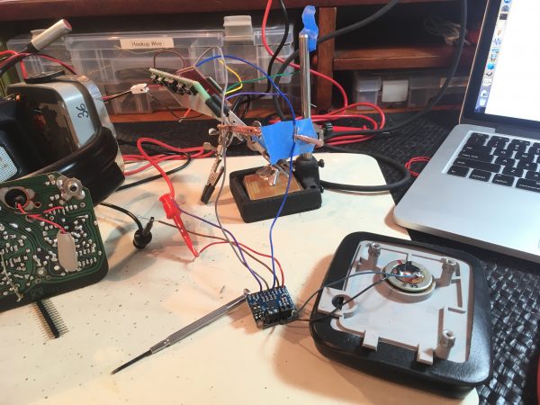
The first job is to find a way to interface with the audio. There is what appears to be an external input jack, so I plugged some music in there. I could hear it in the headphones, but very very faintly. Let’s bust out the ‘scope and see what’s going on.
A quick look at the datasheet for this op-amp revealed my problem- the external audio jack is an output, not an input! This makes sense in hindsight. The operator would be using the two-way radio, and the jack would be so a supervisor or co-worker could plug in and listen along. The audio I was hearing was leakage current from driving the op-amp backwards. Neat!
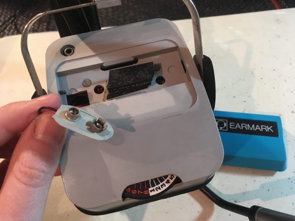
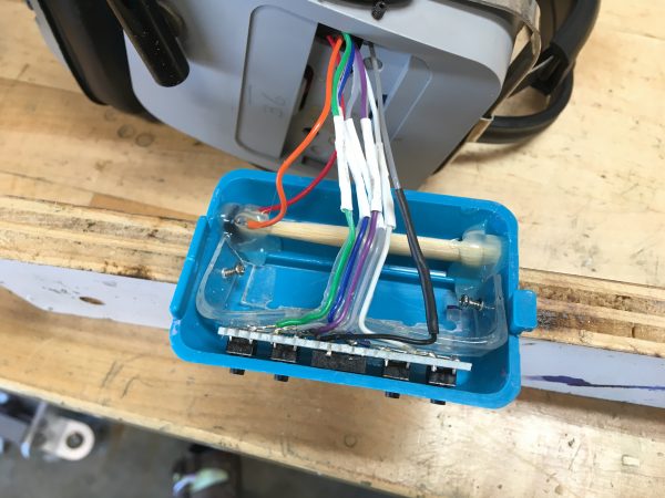
After a bunch more circuit tracing, I decided there wasn’t a great place to tap in to the old radio hardware to gain access to the speakers. Not without introducing a lot of audio noise, anyway. However, there was a nice harness that runs from one earpiece to the other (through the headband) with a 0.1″ header on each end. Some tracing revealed that both speakers were available in this header! That meant I could simply repurpose this header and gain access to the speakers directly, all while being non-destructive and reversible.
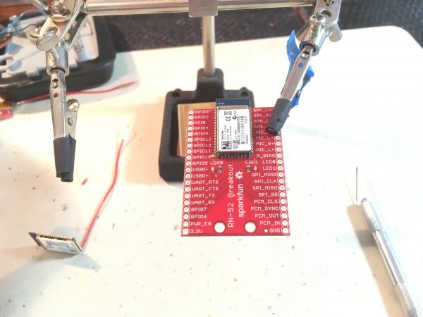
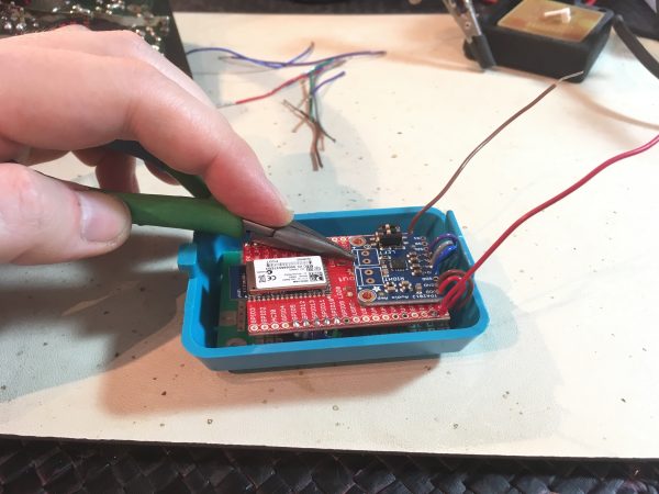
Normally, for a project like this, I would design and lay out a PCB with whatever chips I needed to do the job. However this seemed like a good opportunity to try out all these “maker” products that the kids use today. Turn-key breakout boards that solve a specific problem are all the rage, and they could be a quick route to a solution. They certainly aren’t cheap- a $20 breakout board often has a 25¢ chip on it, but hey, my time is worth something, right? Well somebody’s time is worth something.
This bluetooth module is designed to be surface-soldered to a PCB, but I’m pretty handy at soldering small pitch stuff like this, so I felt I didn’t need to do so. I had dead-bugged a very similar module back on my microcontroller wi-fi project so I wasn’t concerned. I should have been concerned.
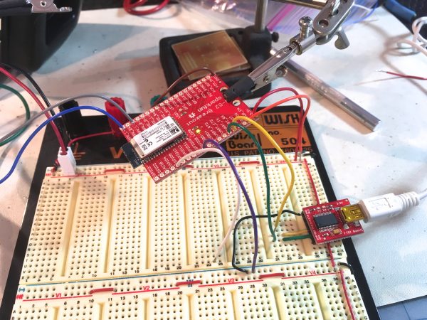
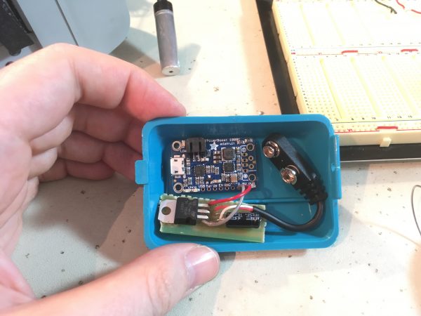
At this point, the project seemed plausible, so I pressed on with a plan. My idea was to reuse the 9V battery compartments on the outsides of the headset. Modern technology is such that there is plenty of room for bluetooth audio components on one side (radio and amp), and power components (LiPo and charger) on the other. I can make these into bluetooth headphones entirely within the battery compartments of the original unit, which makes me very happy (and tells you a lot about how far technology has come).
The RN-52 module is great, but only produces line-level audio. It claims to be good enough for headphones out of the box, but it definitely is not. Headphones for ants, maybe. I needed to supplement it with an amp, so I chose the TPA2012 class D amp from Adafruit. This is a very cool little unit! Surprisingly powerful and very small.
I wasn’t able to find a LiPo charger that outputs regulated 3.3V, which is what the RN-52 needs. There are a lot of LiPo managers on the market, but they all seem to produce 5V regulated outputs. I ended up adding a low-dropout 3.3V linear regulator and a couple of caps to get it down to 3.3V. It seems strange to me that there isn’t a better way to do this, but I wasn’t able to find one.
Everything seemed to be going great, but this is when the trouble started. I had traced out all the circuits and had interfaced to the Earmark’s speakers through the PCB’s headers, and had supplied power through the original power bus and confirmed all the boards were working. However, I would consistently get very poor audio quality and a lot of interference. No matter what I did, the left side never sounded good. I switched leads around on the amp and the bluetooth module to isolate where the problem was coming from, but it was always that left speaker. The audio quality overall was pretty poor also because it turns out these drivers are unusual. They are not 4Ω or 8Ω speakers like you’d expect to find in headphones. They measure 260Ω! That’s an enormous load for a speaker, and I had to crank the gain all the way up on the Adafruit amp just to get something at reasonable volume. With the amp cranked up, I still only got about 80% of typical maximum volume, and distortion was evident. Not a great setup.
After spending several days experimenting and diagnosing, I came to the unavoidable conclusion that the left speaker was blown, and I was never going to get good quality out of either them anyway because of the 260Ω drivers. My plans to keep the headset all original were collapsing around me. I had no choice but to replace these drivers with modern ones.
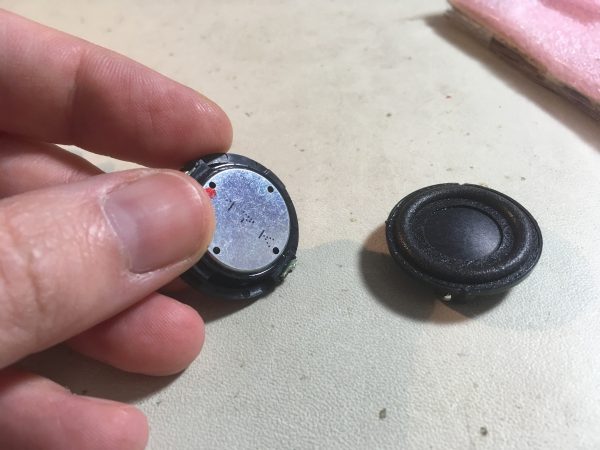
The speakers were glued into the housings, but after almost 40 years, the factory glue had no fight left in it. A light twist with some pliers and the old speakers popped right out. After installing the modern drivers, I still found I needed to remove the original PCBs from the circuit to eliminate the rest of my interference and sound degradation. I was effectively powering up all that old radio gear for no gain (pardon the pun) other than access to the speakers. I made 0.1″ header connectors to match the internal over-the-head harness, and the PCBs were bypassed.
So, here’s the thing. The original PCBs were now totally out of the loop. Also, a 1980s two-way radio is heavy. Since the PCBs were no longer part of the circuit, they were dead weight, and I fancy actually using this headset for extended periods. I’m not doing an internet “maker” stunt here. I’m trying to build something I will use in the real world. It just made sense to remove the PCBs. My plan to keep the headset original continues to implode, but it makes no sense to have them be too heavy for comfortable use just for the sake of having original PCBs inside, doing nothing.
There’s one more problem left- I need access to my button controls, and to the charging port for the battery. Right now these are trapped inside the battery compartments. I could cut holes in the original battery covers, but I wanted to take one more stab at maintaining originality. I decided to try and copy the original battery covers via resin casting. I could have 3D printed some, but that wouldn’t look as nice, and I’ve been wanting to try resin for a while, so it was a good excuse.
Hey Patrons! I have a video all about resin-casting these battery covers, so check your email/Patreon feed for that. If you’re not a Patron, you’re missing out, so sign up now! I’ll show the final result here, but the process is pretty interesting and you’ll want to watch it.
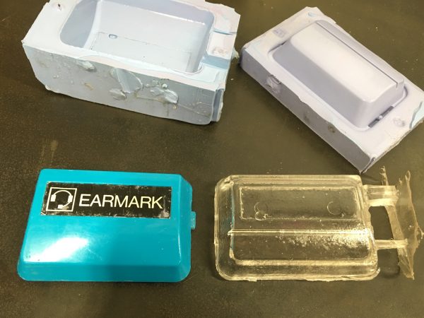
You’ll need to watch the video to see the whole process, but the short version is that I made two molds and four attempts to resin-cast this part, and I simply couldn’t get good results. Resin casting is trickier than the 68 YouTube videos I watched make it look, and I never got a part I was happy with. I got one almost-very-nice mold, but I had trouble getting the resin parts themselves to cure properly. They always ended up rubbery, as though there wasn’t enough hardener in the mix (despite careful measurement and extremely thorough mixing). In any case, I learned a lot, and it’s definitely an interesting process that I will try again some other time.
At this point I had a moral quandary. I set out specifically to maintain the originality of this headset, and to do everything reversibly. Well, by now I have already removed the factory PCBs, soldered in new speakers, and moved several wires inside that were soldered and needed to be relocated. I think the great ship Originality And Reversability sailed a long time ago, leaving me on the wharf oblivious to what just happened. I got comfortable with the idea that I was going to cut holes in the factory plastic for this project, and got to work.
I decided to at least respect the original’s design, and make my changes tastefully. Those failed resin parts turned out to come in handy, because I could practice several operations that I was going to need to do to the original battery cover. I only got one chance to do this perfectly, so having a copy of the part (even a poor copy) to practice on was immensely valuable.
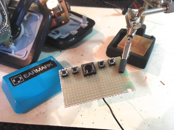
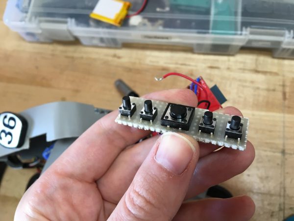
The first challenge was exposing the buttons on the control panel that I had made to fit inside the battery compartment.
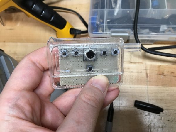
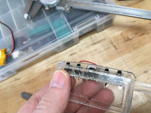
I learned several critical things in this practice attempt. First, I needed a better way to measure the button positions. You can see how off I was there. Second, my buttons are too short. The plastic is a lot thicker than it seemed (go ’80s), and my tactile switches don’t poke through far enough to use. Third, I decided I didn’t like this layout, because it would mean cutting through the Earmark logo in an off-putting way. It would look like a hack job, not a Blondihacks job.
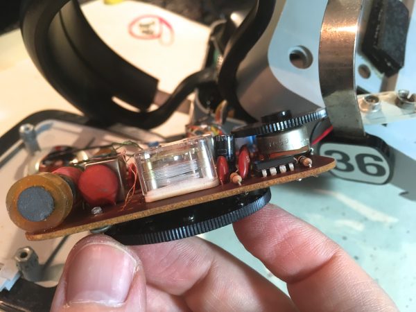
Instead, I decided to remake my control board into a slim form factor that would fit along the top edge of the battery cover.
Once again, I practiced drilling on the failed resin-cast parts, This time with a lot more math and being a lot more patient with the calipers.
I’m so glad I had two practice shots at this, because that was exactly how many I needed to make all the mistakes. My final mistake was that I failed to notice the large play/pause button is not on the same centerline as the small buttons. I needed to account for that in my hole layout.
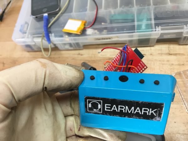
I think having the buttons along the top is much nicer and more respectful of the original design. I like to think this is how Earmark might have done it if they needed to add five control buttons to the device.
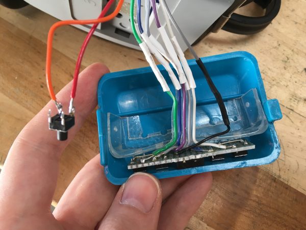
Now I had a new challenge though. The top-edge location is way more challenging than the front face for securing the control panel. It also takes more space, so I no longer had room for the bluetooth and amplifier in there. I went back to the electronics bench, cut all my harnesses, and extended them so I could move those modules inside the earpiece. That was a bummer, but it had to be done. At this point we’re in week seven of this quick Saturday project.
Securing the buttons was still a problem, though. It’s a tricky angle, and there’s nothing in there to anchor to. I didn’t want screws showing anywhere, so what to do? Well, failed resin-cast parts to the rescue again!
I didn’t want to rely on any type of glue here, because glues just don’t tend to hold up long term, and I wanted to actually use this headset in real life. The plastic is quite thick on the sides of the compartment, so with the U-shaped resin bracket holding the buttons in place, I was able to put small screws into the sides just deep enough to hold everything, without the screws coming through and being visible.
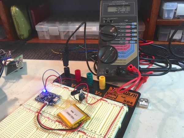
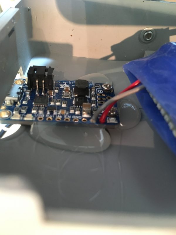
Finally, it was time to install the power components in the other ear. I needed access to the USB port on the PowerBoost 1000C for charging the battery. Since I had failed to copy the battery cover part, I moved the charger inside the earpiece. There was a large gap where the tuning dial used to be which was a perfect fit for the board edge with the USB port.
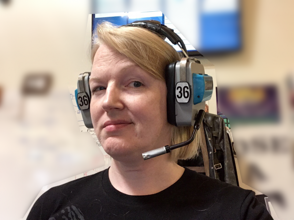
I’ve been wearing these at work every day for several weeks, and they’ve worked out great. There are a few little quirks. Because the RN-52 has no “off” or “sleep”, it consumes power all the time. With the big LiPo I put in there, they easily last all day, but I do need to plug them in to charge at night. Second, there is a safety issue with the RN-52. The various status and acknowledgement beeps that it makes can be very loud. Like, insanely loud. I’ve learned to turn the bluetooth’s volume all the way down, and adjust the source volume on my phone as needed. This keeps from the RN-52 from deafening me at random. The RN-52 also beeps very audibly every 10 seconds or so when the phone goes out of range, which tends to annoy my coworkers when I go to a meeting or to the restroom. A workaround is to disconnect my phone before walking away, but this is a pretty ridiculous feature of the RN-52. Things like this are why people hate bluetooth. One last improvement I made is to stuff the earpiece cavities full of foam rubber. The cavernous 1980s plastic shells tended to create an echo of ambient sound in the room. The foam rubber fixed that.
For a lot more build details, be sure to check out the Patron video! Sign up on Patreon in order to see it, as well as all the other exclusive companion video content that I’ve been posting. Thanks to all my current Patrons for making this all possible!
Hey, have you seen Michal Zalewski’s resin casting guide? http://lcamtuf.coredump.cx/gcnc/ch4/
He has a few ideas for what can keep it from curing, and lots to say about resin choices.
Oh, great tip, thank you! I’ll check that out.
I do resin casting too, 17 years now, making reproduction parts for classic cars. Here’s a quickie how to I did a while back. http://partsbyemc.com/pub/mold-making.htm
For resins, almost everything I use is from Smooth-On.
I didn’t notice any mention of the microphone. Did you get/attempt to get that working with the RN-52? Would be pretty cool to also do calls on the headset.
Great question! I left out the microphone because the article was already getting too long, but I did investigate it. There’s something fishy with it, because there’s only one wire leading to it. No chassis ground, nothing. You can see it in one of the photos- there’s one brown wire coming out of the hole leading down the mic arm, but that’s not enough to make it work. I need to disassemble the microphone element itself to see what’s going on and why there is a wire missing. I wasn’t able to figure out how to disassemble the microphone without ruining it- I suspect it’s all well-glued together, and I don’t want to destroy it. I’ll likely revisit it at some point, because I agree it would be super cool.
What a great project! I just love the look of the manually laid out circuit boards! And I would totally wear these every day if I had them, too! 😀 Also, that Micronta 22-850 looks like a rebadged Fluke 🙂 (I’m probably wrong).
Thanks! 🙂
The Micronta meter is about 35 years old, believe it or not. A Radio Shack house brand from the 1980s that I got when I was six years old. It’s been good to me ever since.
Looking at your photo of the crystal, there’s a clear date code on it: 7917. So that’s 1979, week 17. Which makes me think that the 2180 on the ferrite rod antenna is also a date code, 1980 week 21. Would that be plausible?
Oooooh, date codes- of course. I bet you’re right!
…or perhaps 2/80? That number 1 looks awfully like a slash in my handwriting. I sort of remember that final assembly and tuning (and testing, QC) was done in-actory and had to be marked by the tech. Maybe there’s a set of initials somewhere?
Also a good thought!
I scrolled down here to write exactly that – I’m sure it’s 2/80!
4 Ω or 8 Ω headphones are still quite rare. The cheap stuff usually has 32 Ω, good hi-fi and semiprofessional ones have (or used to have) 600 Ω, and professional equipment can have 2 kΩ.
Mini-speakers with 4 Ω or 8 Ω are usually designed to be used as beepers in non-audio devices, e.g. to play back warning or alarm sounds, where the distortions of piezo drivers are not acceptable.
High impedance headphones were a logical consequence of having relatively high voltages (30 V or more) available in the amplifiers. You can get away with very low currents through the headphones, and so you don’t need fat and expensive transistors to drive them. A few tiny small-signal transistors are sufficient, even in a class A configuration. Often, the regular amplifiers for the speakers were also used for the headphones. A switch disconnected the speakers, and the headphones were supplied via a small resistor from the speaker amplifiers. Because of the high impedance of the headphone, the resistor did not have a significant influence on the sound. (It does have a negative on with low-impedance headphones.) This setup does even work with bridge amplifiers, you simply use only one half of the bridge via a resistor, and, in case of asymmetric supply voltage, a small decoupling capacitor in series with the resistor and the headphones.
The 32 Ω headphones are a direct consequence of mobile audio equipment. Running a compact cassette player from two or three cells limits your available voltage to 3 V / 4.5 V. Some rare ones even worked on a single 1.5 V cell. So to get the same power to the headphone, you have to increase the current by decreasing the impedance. The typical common ground configuration forced by using a TRS plug prevents you from using bridge amplifiers in that situation.
Modern high-tech headphones and earphones have impressive capabilities of playing back low frequencies, compared with cheap 1980s headphones. Partly because they use very powerful rare-earth magnets, and partly because you can push even more energy through the coils with modern equipment. The impedance had to drop below the common 32 Ω, the amplifiers have changed from cheap bipolar transistors to low-resistance MOSFETs, and they are powered by low-impedance lithium-based cells that provide about 3.6 V per cell.
Great info, thanks! That’s a lot more than I knew about headphones (as was no doubt obvious 🙂 )
I wouldn’t worry about being too hipster. It’s been my experience that modern day hipsters lack the required skills to do anything this complex. They may be aficionados of the end result, but as for making something? Not so much…
Those headphones are utterly ridiculous, and I love them!
(I now need a VR headset with a similar industrial design.)
i usually call this kind of hack ‘redneck’ rather than ‘hipster’. sometimes ‘ghetto’ applies (in the same vein as early afrotechmods shenanigans), but i dont think its as fitting as ‘redneck’ in this case as it kinda has a ’70s trucker vibe to it.
as for dev boards its often easier to find chinese knockoffs of sparkfun boards and save like $18. of course that usually means 4-6 weeks shipping.
When James and I found that headset in the M. Mahon collection, we -=knew=- it was perfect for you.
<3 <3 <3
Hmmm. I think aircraft frequencies have been AM and in the 108-136 MHz range for quite a long time. It looks like prior to creation of Multi-Usr Radio Service (MURS) in 2000, 154.57 MHz was a business band frequency and it’s now called the Blue Dot frequency under MURS. (I didn’t dig far enough to determine what that means — it wouldn’t surprise me if business license holders were still allowed to use it.
Anyway, do you have any plans for the air variable capacitor and knob?
P.S. if all of those (mostly) defunct airline headphones were part of the same collection, thanks Michael. I picked up a few to tinker with but they obviously have much less space to cram modern electronics.
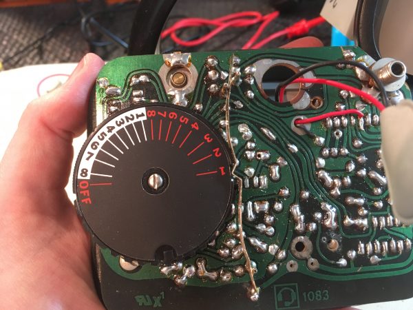
You say the PCBs are single-layer single-sided, but on the transmitter board I see at least a ground plane on top and wave soldered traces on the bottom? And what appears to be plating on the through holes. Am I getting confused or should that not be single-sided, dual layer for the transmitter?
Yes, I misspoke there. One of the boards is definitely at least double-sided.
Now the important question, is your shopcat a fellow worker?
That’s Sprocket H.G. Shopcat, and I’d say she’s more of a supervisor. At least, she must be, based on how much she disapproves of everything I do.
I picked up a bunch of BT boards from icstation for under $4US each and dropped one in each car that doesn’t have BT audio. USB micro socket for power, 3.5mm jack for output. The ones I got don’t appear to be available anymore, but there are plenty of other super cheap options, some with amplifiers.
If you just want to mod old cans for music, get a Blackberry Music Gateway. 3.5mm stereo out jack. Mini B USB for power. Capacitive sense top surface with a red/blue LED for control and indication. That’s all there is to it. Toughest part would be modding the touch sensor to some unobtrusive bit of metal on the headphones and extending the LED to somewhere.
Just a fyi with needing a separate 3V linear regulator, I haven’t looked at the schematic for the adafruit lipo/power board, but it might be an easy bodge to tweak the feedback resistor on the switching 5V regulator to instead regulate to 3V (assuming the chip can do buck/boost, if not then you would be stuck with Vout>Vin anyways in which case ignore my senile suggestion). That’d certainly save you some wiring and be a bit more efficient. Anyway, great job and I love how clean it all came out in the end! Very tempted to try my hand at building something similar.
I don’t think your soldering skills are suspect, it’s more that the wire you chose was so stiff that it had enough leverage to remove the pads. I switched to using thinner and softer wire, and I’ve never looked back.
Awesome hack!
This is up on Hackaday. https://hackaday.com/2018/10/30/a-bluetooth-upgrade-for-an-unusual-set-of-headphones/