Wrangling the angry pixies
This project has an exclusive Patreon video about the internals of the electrical controller.
Sign up now to see it!
The raison d’être of this steam boiler project has been to have a boiler than can operate steam engines in a pleasant indoor setting. No smoke, no fumes, no dead dinosaurs being burned (on site). We’ve built an actual boiler, so now it’s time to finalize the part that makes it an electrical one.
My basic idea is to build a box around the heating element that sticks out of the end of the boiler. This will dress things up, keep all the high-voltage stuff out of harm’s way, and provide easy servicing of the parts. There will necessarily be wiring running to the far end, where the thermoswitch is located. This wiring will be hidden inside the base of the boiler. The idea is to make it all look kinda like a traditionally-fired boiler, and not like the glorified electric tea kettle that it kinda is.
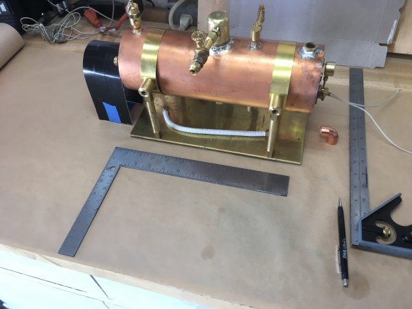
Mocking up the electrical box with cardboard was very important here, because I needed to get the size just right. It needs to cover the heating element, but leave the expansion port on the end of the boiler clear. The box also needs to have enough interior space to hold the contactor, power switch, fuse, wiring, and so forth. It was also important that the box not actually touch any part of the boiler, because it would conduct heat into the electricals and damage them. Once I had the dimensions perfect, I was able to easily transfer the dimensions from the cardboard to the real stock.
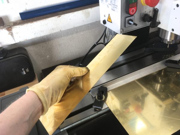
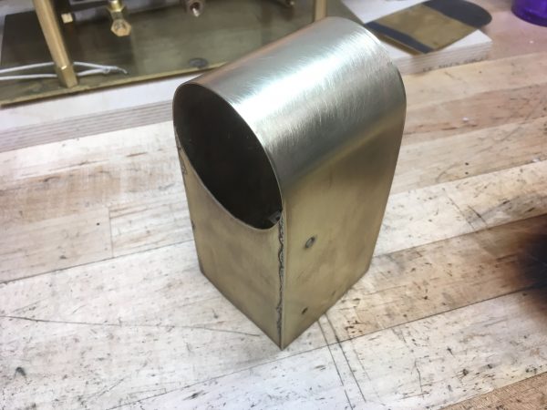
I wanted to make this box out of brass sheet, because I felt it would look nice. You may recall the trouble I had previously trying to work with brass sheet without proper sheet metal tools. I certainly recalled that. However, we now have a glorious and lovely milling machine here at Blondihacks World Headquarters, so I decided to give that a try. I’m happy to say it worked beautifully.
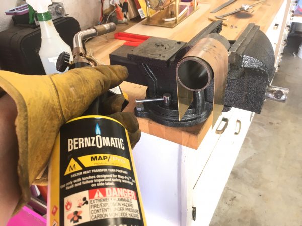
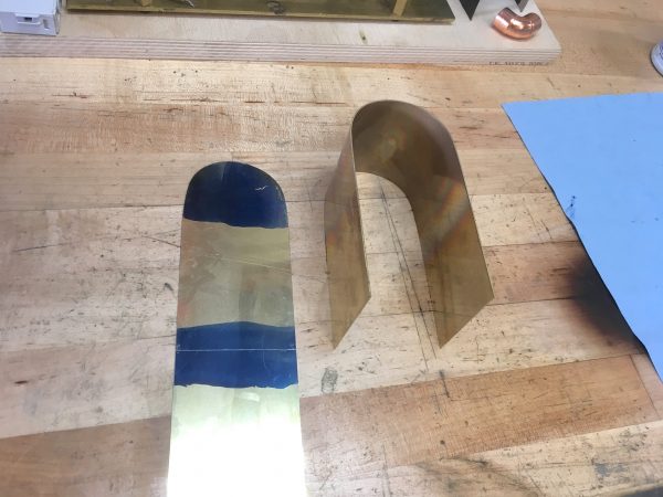
Next, I needed to make the curved top of the box. The junk pile provided a scrap of pipe of roughly the correct radius for the curve I wanted, so I used that as a form.
The next challenge was the rear plate for the box. I wanted it to form a round opening with the top surface, so that it neatly slips over the heating element without touching it. This means I needed a half-circle cut-out in the part. I was very happy with my milling-machine cutting method, so I wanted to use that, but I needed a curve this time. There’s no fancy CNC here- my mill is a manual machine. It does, however, have a DRO, and DROs often have a curve-cutting feature. The way they work is you input various dimensions and other information about the curve you want, then the DRO gives you a “recipe” of sorts. It puts numbers on the display for each axis, and you have to zero them out with the hand wheels. Then you push a button and it gives another set of numbers. You’re effectively cutting a polygonal representation of the curve. You might call it Human Numerical Control. There’s a fair amount of skill in doing it though, because you need to move smoothly in multiple dimensions at once with the hand wheels. It feels like playing the drums or double-clutch-downshifting a racecar in a corner. You need multiple limbs to be moving independently.
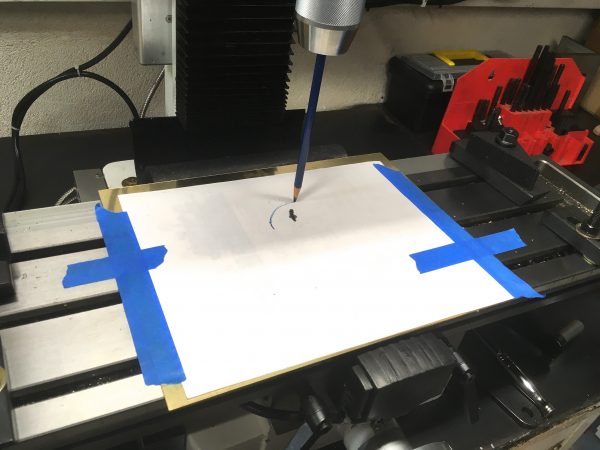
After practicing for a while, I decided this would probably work, but it was also a bit of silly overkill. I decided to go old school instead, and did a simple layout of the curve on the part.
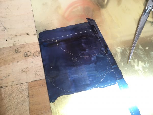
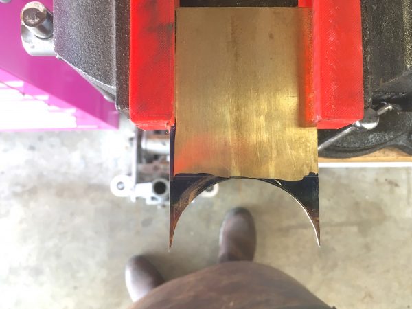
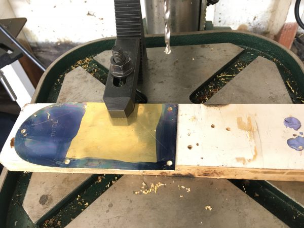
To cut the curve, I chopped out the rough outline with a hacksaw, then finished it up to the line with a Dremel sanding drum. This worked perfectly and was a lot simpler than the DRO method (although that was fun to learn).
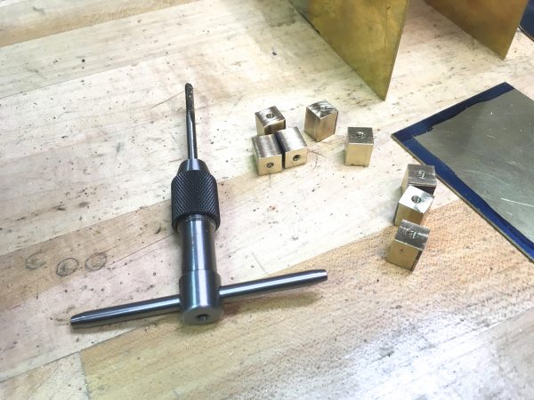
This thin sheetmetal box needs some mounting points. We need to be able to affix it to the base, and we also need a removable door on the front. Both of these needs will be met with some square screw bosses.
Now we were ready for some assembly, so it’s time to fire up the torch. All the parts of this electrical box are silver soldered, starting with the mounting blocks. This was a bit tricky, because they are small and the wind of the torch wants to blow them around. I used a combination of scrap blocks to weight them down and provide backstops to keep them from moving. I didn’t succeed perfectly (some of them definitely moved), but they came out okay,
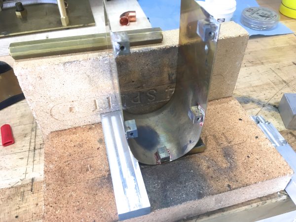
Next, the back wall needed to be attached. This was tricky, because I wanted the sheet metal to sit precisely edge-to-edge, with no misalignment or overlap. Once again, even with everything perfectly arranged, the torch would tend to blow things around. I handled this by arranging the pieces carefully on the fire brick, then put some weights on top to keep it all still. I also applied very light clamping pressure to the sides to keep the curves tight together. This all worked well to hold the alignment precisely, but there was an unanticipated side effect- as the brass softened from the heat, the weight on top tended to deform it. The back was perfectly fitted when I was done, but the sides had a slight bow in them. I was able to mostly correct this after the fact, but it’s not perfect. Live and learn!
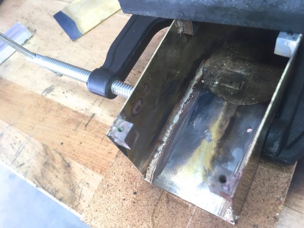
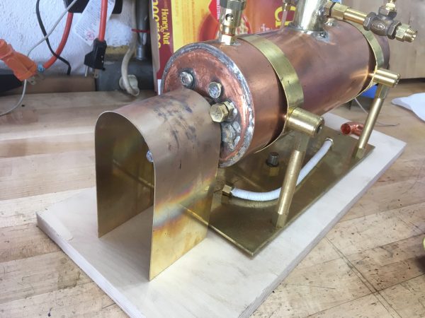
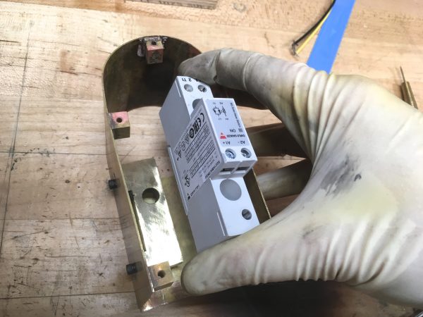
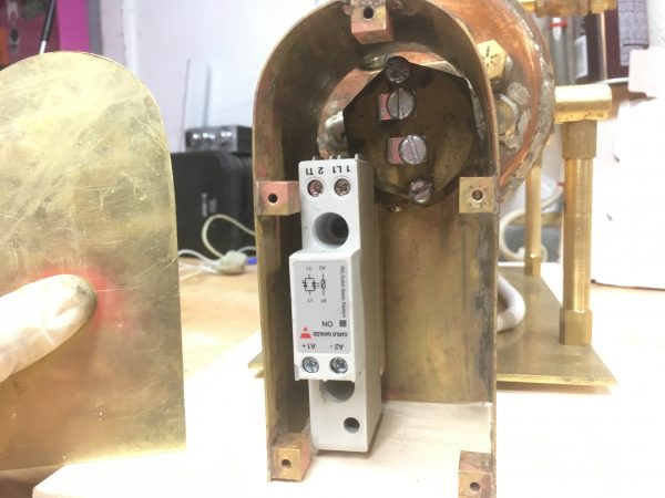
The next step was to figure out how to mount the contactor inside. I wanted it suspended off the deck, in case water gets inside this box. Steam engines are wet environments, so it’s wise to anticipate water getting everywhere you don’t want it. The other catch is that the contactor has a very large heat sink on the back of it. This is presumably needed when the contactor is switching heavy loads, such as big AC motors. My application should be pretty easy for it, bit I still wasn’t totally comfortable foregoing the heatsink. I needed to do something though, because with the heatsink there was no way the contactor was going to fit.
My solution was to remove the heatsink, then use those attachment points to mount it to the wall of the box with a heavy chunk of brass. This should effectively make the entire electrical box into a heatsink for the contactor. The electrical box is designed to enclose but not touch the end of the boiler, so it should remain relatively cool.

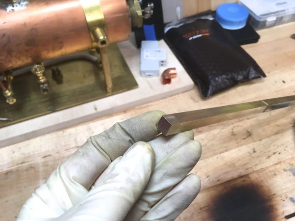
With the fabrication on the box done, it was time to clean up all the silver soldering mess. People always say you can clean up silver-soldered parts by pickling them in something like Sparex #2. I’ve honestly never had this work very well, but everyone says it’s the thing to do. I bought some fresh Sparex and gave it a try once again.
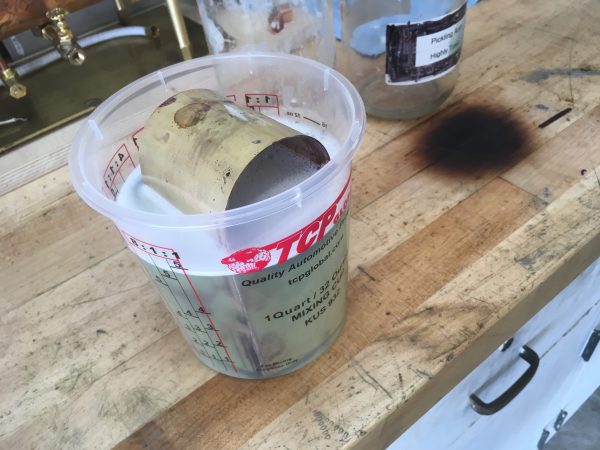
With yet another failed attempt at pickling, I went back to my old standbys of sandpaper and Scotch Brite.
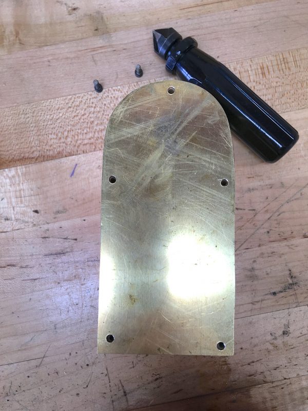
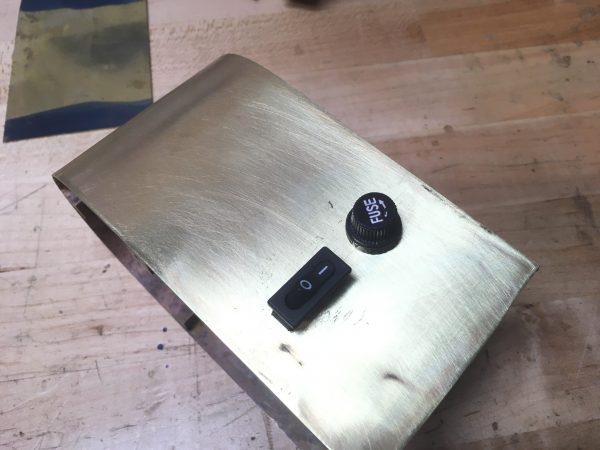
The next part to make is the door on the front. It’s held on with five cap screws, which is completely unnecessary, but looks very “steamy”.
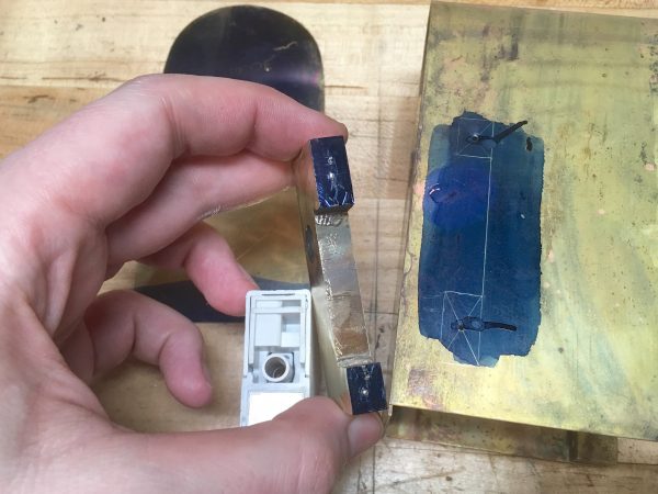
For the door’s mounting hardware, it would be nice if we could just measure and lay them out, knowing they would line up. However, recall that it was difficult to keep the mounting blocks from moving during soldering, so their positions are all little… freestyle. Luckily, transfer screws to the rescue. I talked about how great these are in a previous post and that hasn’t changed. They are, in fact, still great.
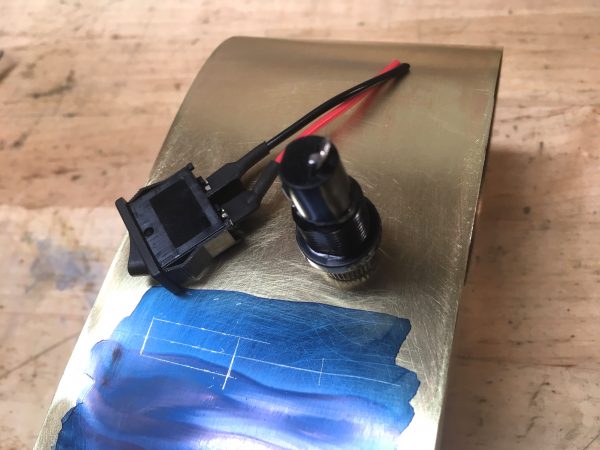
Now we need some controls. There needs to be an on/off switch, of course, and very importantly there needs to be a fuse. We mustn’t lose sight of what we’re building here- a high voltage circuit dunked in water. We’ve intentionally built a toaster in a bathtub. This is no time to skimp on safety. A fuse is one part of that.
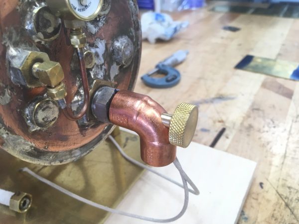
The vast majority of the wiring is done inside this box, but there’s one part external to it. The big heating element lives in one head (inside our new box), but the opposite head has the thermoswitch in it. This is the 120V temperature sensor that tells the contactor when to do its contactor thing. The wires for this thermoswitch need to get from one end of the boiler to the other. I made a YouTube video all about this, and it’s available here. If you like this video, sign up on Patreon. I post lots of private videos just for Patrons!
The final step is to wire everything up! I won’t be blogging this part, but I did shoot video of the whole process. That video is only available to Patrons, so sign up now to see it! I post lots of special content just for Patrons, so sign up to get the full Blondihacks experience.
I do want to cover one wiring topic here, in the interest of safety. As I said, we’ve basically built a toaster in a bathtub here, and the most important tool in our safety toolkit is grounding. Every single piece of metal on this boiler is separately grounded to a proper third-prong plug, and it should only be used in properly grounded outlets. The heating element inside the boiler has a protective coating isolating the high voltage from the water, but if that should fail, the water, and by extension every metal part touching that water is suddenly energized at 120V and eight amps. You really want that current to be dumped to ground without passing through your pancreas, hence the meticulous grounding. I cover all the details of the grounding features in the Patreon video, but I didn’t want to go without mentioning it here in writing as well.
To see the boiler powered up and running an engine, you’ll need to watch the Patrons-only video!
The electric steam boiler project is now complete, which is hard to believe. It’s been almost a year-long project, but I’m very happy with how it turned out. You’ll be seeing more of it in these pages occasionally, as I’ll be making tweaks and improvements to it. I’m thoroughly enjoying my forays into steam engineering, so this won’t be the last we see of this charming little Victorian death machine.
“German engineers are taken out back and shot for this sort of thing, so they don’t have a word for it.”
Our engineers in training get a proper spanking for the first misaligned part or hole that they will rarely forget. There are rumors that the offenders won’t be able to sit for a week. The few ones that misalign a second part during training will be subject to a very painful secret ritual that ensures they won’t ever misalign a third part. And yes, if a professional engineer misaligns a part, he will be instantly shot. The last time this had to happen was about 150 years ago.
But our engineers have to create products intended to be used by untrained mere mortals, and so they invented the Langloch (https://de.wikipedia.org/wiki/Langloch), perfectly aligned as any other hole, but capable of compensating for misalignments, even at ridiculously large scales like several thousand micrometers.
Well, as an engineer, the designs I’ve rendered were all perfectly aligned.
But they had to be implemented and built by skilled tradespeople. Therein lay the problems with misalignment and compensation. Usually the solutions were slotted holes. Sometimes the issues were so bad they had to be corrected by cutting and welding (“blue-flame field engineering”) which I hated.
Sometimes it came to fisticuffs:
Skilled trade: “This can’t be done… you should do it my way.”
Engineer: “Just MILTFM” (Make It Like The F#$% Drawing)
Skilled Trade: “F@#$% off”
An IEC320 C14 socket for the power cord brings benefits to electrical appliances large enough to embed it. A permanently attached cord often gets in the way, unravels from the device while you are carrying it, drags on the floor and trips you. I speak from much experience 🙂 IEC cords, on the other hand are easy to replace, easy to pull through various holes between the outlet and the place where you want to install your boiler, and easy to detach when installed there in case you need to move the boiler to the workbench to make repairs. IEC sockets are also available as an integrated module with a switch and fuse, reducing your parts count and requiring only one hole instead of three.
I tried to incorporate a power socket, but there wasn’t room inside the box. Those sockets are quite deep.
Look at https://www.ebay.com/itm/263446639971, a horizontally oriented socket with switch (despite the item description, the fuse is not included). If turned on the side, it is only 2cm wide, and should fit in that space to the right of the contactor. Are you sure you can’t fit a horizontally oriented socket in there? It looks wide enough, but I suppose if it doesn’t fit, it doesn’t fit. As for the depth, it is true that spade connectors might be too long. You can, however, clip the blades off the socket and solder wires directly to them, bringing the total depth to 2cm. The contactor has screw terminals, and you really only need one end of the wire free.
1) Love the boiler project. Electronics are one thing. Machining another. But mix in thermodynamics and you have magic.
2) Someone’s a fan of AvE!
Haha, yes, I have shamelessly stolen some of AvE’s idioms for this post. I am indeed a long time fan, and never miss one of his videos. I watch your channel too, as a matter of fact!
I’ve always used Sparex hot, in an old crock pot: that’s how I learned back in my silversmithing days. It doesn’t entirely remove the copper oxides but it sure makes them easier to scrub off.