Time for our girl to learn some new tricks.
If you were to ask me what questions I get asked the most in my life, the list might look something like this:
1) Who the hell are you?
2) Wait, you like computers?
3) Wait, you like machine shops?
4) Wait, you like race cars?
5) Can I hold your cat? She looks very soft.
6) How did you get in here? I’m calling the police
7) No seriously, who the hell are you?
8) Can you do more projects with Veronica?
9) Can you hold my beer?
10) For reals, who are you and how did you get in here?
As you can see, Veronica makes the top ten. If you’re new around here (and if my analytics are to be believed, a lot of you are), let’s recap.
You see, way back in 2011, when CDs were maybe(?) still a thing and Blackberries still thought maybe they could make a go of it, I decided to build a computer. Usually when I tell people I built a computer, they think I went and bought a power supply and an ATX motherboard and some silly neon lights and whatever else the kids do to play Crysis these days. Then I have to explain that, no, I mean I built a computer. You know, like Steve Wozniak. The next question is, “Who the hell is Steve Wozniak” because all of my co-workers are under 30 and Steve Jobs did a lot of rewriting of history before he donned his last black turtleneck.
Anyway, more to the point- I was inspired by Steve The Smarter to build my own computer from TTL parts the same way he had done with the Apple II. I’ve always been a software person, and while I learned enough electrical engineering to be dangerous in school, I had not done much in the realm of actual computer design. I wanted to give it a shot. You can read the whole story here, if you need a refresher.
I wanted a computer in the vein of the 1980s home computer wars. For those of you who weren’t there, it was an amazing time. There were dozens of competing brands, each with a whole line of machines, all entirely mutually incompatible (often within the same brand). The world had not picked any standards to speak of, and it was a marketplace of (mostly bad) ideas. Among all the many things I did not know that I didn’t know about computer engineering, one major thing stood out. I had always thought of computers as basically a CPU with some RAM and I/O hanging off a bus. Good old Von Neumann, right? For 1980s computers, this made them really quite simple because TTL logic is basically digital lego, clock speeds are low, and buses are narrow. It should be easy to build such a computer! What I failed to appreciate is that any given 1980s computer was not a CPU and some RAM hanging off a bus. It was a crazy mad scientist method of generating video based on the fever dream of a hardware engineer who had spent a little too much time watching The Last Starfighter, and maybe not quite enough time reading reference circuits for the parts in her drawers. Every 1980s computer was an experiment in a new way to generate graphics, and everything else (CPU, RAM, etc) was an accessory to that effort. This is crucial to understand, and it’s something that nobody in the home-brew computer world ever seems to talk about. I mean sure, if you’re happy talking to your “computer” over a serial port and having it spit ASCII back at you at 300 baud, great. Go nuts. Personally, I like actual fun. And that means pixels.
It was with that pile of lies in my head that I plunged into a 5 year odyssey of attempting to build a GPU of my own design. Because I don’t know what I’m doing, it was largely implemented in software on an ATMega microcontroller, and could spit out passable VGA video while talking to a 6502 over an 8 bit bus. I succeeded in this dream, but juuuuust barely. While I achieved my stated goal of building a computer that you can sit down in front of and program itself with itself, the video always nagged at me. Don’t get me wrong- reverse engineering the VGA standard and bit-banging it out of a 20MHz microcontroller with 10MHz of I/O bandwidth using little more than a logic probe and a complete lack of good decision making skills is one of the finest things I’ve ever done. However, at the end of the day, it wasn’t a good way to do video. Yes, it renders text and a couple of sprites and even plays a decent game of pong, but the implementation was so clunky that I knew it was never going to achieve much more than that.
I had started down this road of designing my own GPU because I couldn’t find one suitable. There are vintage graphics chips still available, but all either output composite video (too old and limiting) or didn’t have video output at all. Often they would output something like 15KHz linearly clocked pixel data, and you were expected to build a video generator to hang off the back of it that generates all the analog waveforms needed to speak to a monitor. This approach made perfect sense when these chips were new, because there were few video standards to speak of back then. Most computers did some form of composite, but as the Apple II demonstrated, it’s possible to be officially “composite”, yet not display properly on most monitors. Other machines like the Apple IIgs technically have composite, but it looks like garbage. The machines renowned for their graphics (Amiga, Atari ST, Apple IIgs, etc) made up their own video standards because existing ones were crap. Many (again like the IIgs) used variations of arcade video, which had its own unofficial-but-defacto way of getting pixels onto a tube. The point of all this is that, as a video chip designer, it made perfect to stop short of generating actual video, because nobody in the 1980s agreed on what video signals we should have. We haven’t even talked about interlacing, resolutions, overscan, color depths, bit planes, VRAM layouts, etc. Those are all entirely other cans of worms that nobody agreed on. You think modern PC video is a wild west of different variations? Oh, honey.
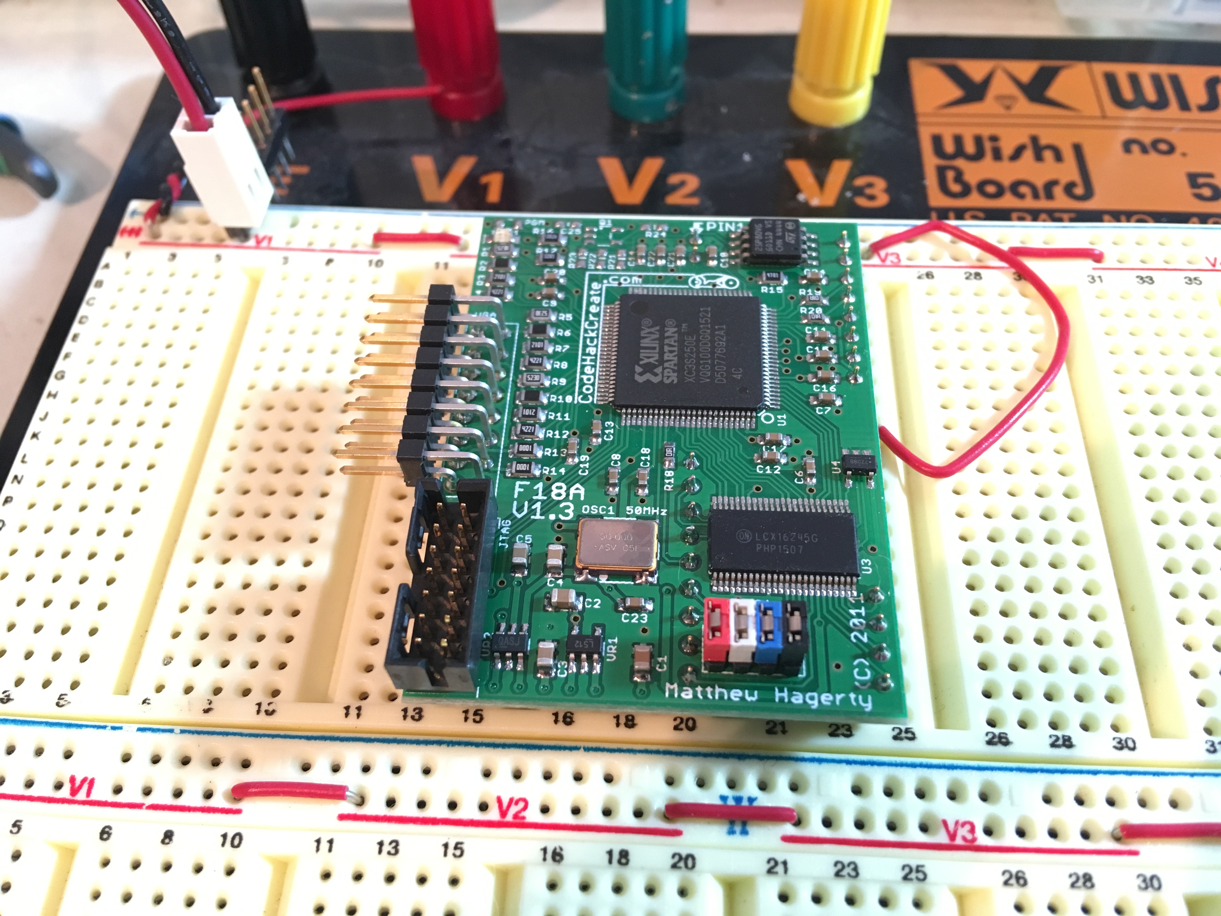
Let’s get back on track here. Well, some time after I finished my own video solution, I stumbled across the thing I had always wanted for Veronica- a real, honest-to-goodness graphics processor that can talk to an 8-bit CPU, spits out VGA, and can be bought new today. It’s called the F18A, and it’s the brainchild of Matthew Hagerty.
As of this writing, the F18A is no longer available for purchase, but Matthew is working on a Mark 2 that supports HDMI(!). I bought mine many years ago when they were still available, because I’ve learned from the retro computing hobby to always buy cool things when people sell them. Projects like this are always labors of love, and when they stop being available (because the creator wants their life back) they will be gone forever. I bought the F18A while I could, and it has been sitting in my junk pile waiting for its time to shine. That time is now, and I want to use it to give Veronica all new video. Let’s do this.
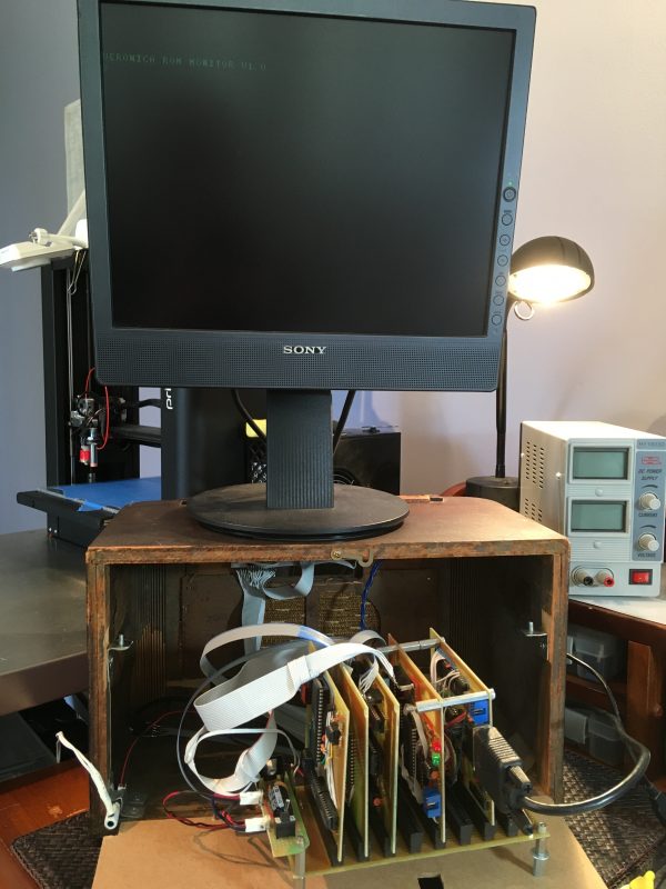
The first step was to get Veronica back on the bench where she belongs. She has been serving as decoration in my living room for several years, and I had no idea if she would still power up.
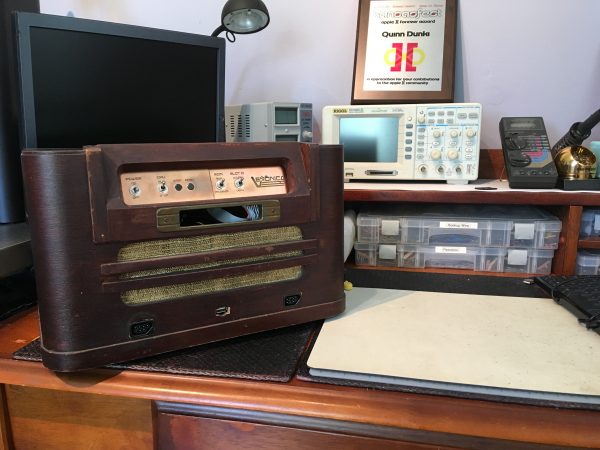
I figured a visual inspection was in order, before applying power.
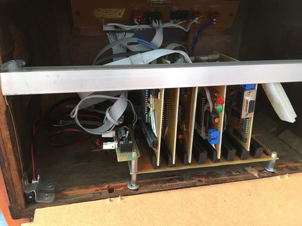
Everything looked good inside. I pulled the board set out and looked everything over. I was quite expecting to see some corrosion, because the copper boards that I etched myself are all unprotected. There’s no sealing coat on them at all, and bare copper will corrode eventually. I still have all the gerber files and photo masks used to make these boards, so I can easily replace them if needed, but it’s nice to see they are still in new condition after eight years.
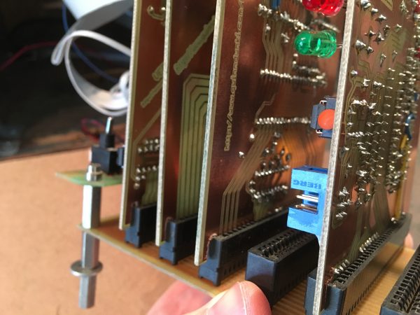
I also checked the alignment of each board with its respective socket in the backplane. I’ve learned in previous adventures that some of my boards have slight size issues with the edge connector. This is due to small scaling errors that crept into some of my photo-etch masks that I printed on FedEx Office printers. Those printers all have a small scale factor to them (generally 1-5%) and you have to compensate for that. I’ve never figured out why those printers scale slightly, but it has been suggested that this is to defeat counterfeiting. That answer sounds a little too “neato” to be true. More likely it’s just that reproducing scale perfectly from software to file format to hardcopy is difficult and most printers don’t do it perfectly. Who knows. I can say that the printer in my office (an HP Lasersomethingsomething) does an amazing job on my mechanical drawings produced from Fusion 360. Those come out 1:1 with a precision that is within the thickness of the lines. In conclusion, printing is hard.
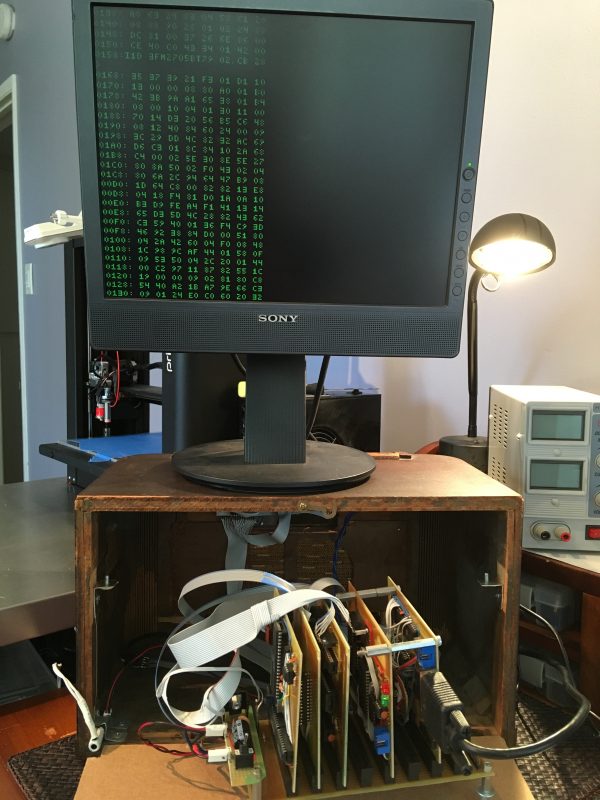
Everything checked out in my inspection, so there was nothing to do but turn it on!
The screen image is quite dim, and this is another problem Veronica has always had. The VGA signals produced are ostensibly within spec (as far as I can tell), but the image is dim. It certainly doesn’t help that this monitor is a piece of gou shi that I bought at a swap meet. It has many issues all its own. One of the many mistakes I made in Veronica’s video system was dialing in the timing precisely to suit this display. I naïvely assumed all VGA monitors should be broadly compatible, so if the image is good here, it will be good anywhere. It turns out this particular monitor has freakishly smaller overscan than average, and on most other VGA monitors I have tried, the left edge of Veronica’s video gets cut off. Fixing this horizontal alignment requires realigning the horizontal timing pulses relative to the vertical blank. If you followed along with the original development of Veronica’s video, then you know that fixing this would be obscenely difficult. Many many hours were spend counting clock cycles in every code path through the huge block of assembly language that is bit-banging the VGA (while also rendering fonts, sprites, etc). Any change requires recalculating a new set of codepaths that all line up with the desired new timing. It’s extremely nontrivial, I was lucky to get it working at all, and thus I live with the quirks.
The screen dimness and alignment issues are two more reasons that I’m excited to try the F18A. I was in over my head with that video generation project, and while I did get it done, and could do it better next time, I’m frankly glad to have someone like Matthew come in and pinch-hit the next inning on this one. That’s all the sportsball metaphors I know, so I hope it was good for you.
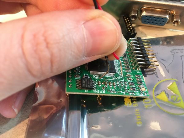
Okay, let’s get to the object of my affection- the F18A itself. What is this thing?
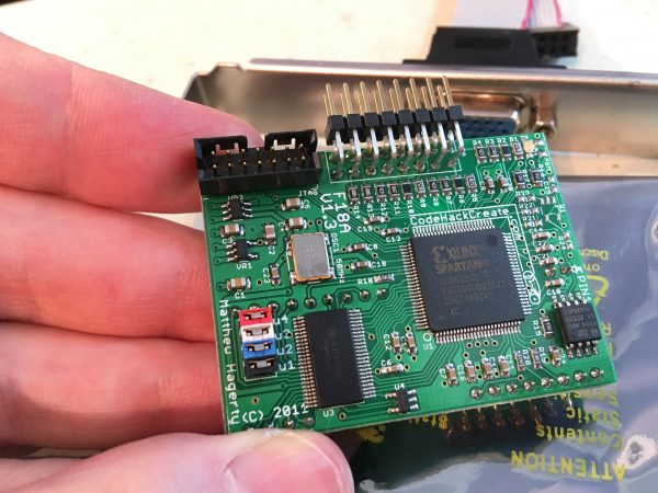
The F18A is basically an FPGA re-implementation of the TMS9918A Video Display Controller, which was used in the TI-99/4A computer (c.1981) to generate graphics, text, and video. The 9918A VDC was later adopted as the standard for the MSX-compatible computers popular in Japan in the 1980s and 1990s. It can also be found in the ColecoVision, some arcade machines, and various other obscure 1980s home computers. The TMS9918A was such a great chip that it spawned a line of video generators, including the super amazing Yamaha V9938, which was the basis for the MSX2 platform. I’ll get angry comments for this, but the 9918A is roughly comparable to the Nintendo Entertainment Systems’ PPU graphics chip, while the V9938 is a decent analog to the Super Nintendo. I say that not to get into a specs argument about palette counts or sprite layers, but to give you a sense of the level of graphics technology that we’re talking about here- we’re talking 2D tile maps and sprites in the 8- and 16-bit fidelity range. This was hardware accelerated video in the 1980s, and it was great. It’s funny that we think of hardware accelerated graphics as an invention of the late 1990s (lookin’ at you, Voodoo), but what really happened is that (as with most things) PCs just took a really long time to join the party. That sound you just heard was three hundred Amiga users flipping their tables in disgust. That happened a lot in the 1990s, too.
Okay, I got off track again there, but back to the point. The F18A is a modern reimplementation of the 9918A, as I said. It is literally a drop-in replacement for that chip for any computer or arcade machine that used it. More than that, Matthew has actually improved the design in several key ways. The most obvious is that the board outputs VGA directly. The original chip primarily gave you digital RGB pixel data, and you were on your own to hang a video generator off the back of that. It did also output NTSC (and later PAL) composite video in the first version, but subsequent chips in the line dropped that. The other cool thing about the F18A is that it has its own VRAM onboard. This allows it to implement new video modes that the original 9918A didn’t have. The original TI-99/4A had 16k of dedicated VRAM (called VDP RAM), which limits how much more you can do. For our purposes, this built-in VRAM is amazing because it makes the board a completely self-contained graphics solution for home-brew computers. It’s so well self-contained that it only implements a handful of the original 40 pins on the 9981A. All it really needs is power and an 8-bit bus to the CPU. Matthew has also documented it extensively, and it’s quite easy to use (as graphics chips go). I was going to also say here that, being a modern implementation, a big advantage is that you can actually get it. The classic chips like the 9918A and V9938 do show up on eBay occasionally, but they are pretty unobtainium. Even if you get one, you still have to implement the video generator yourself, unless you use the older chips that output composite video straight from the chip and you have some way to display that. Video generators right are no picnic to get right (see: five years of my life I’ll never get back). All of this makes the F18A even better. Well, except that you actually can’t get them right now. He’s not currently selling any more of them, and while the Mark 2 (with HDMI!) is apparently still in development, there haven’t been any updates in several months. I don’t fault Matthew at all for the delays. A project like this is a very time consuming hobby, and we all have real lives to attend to. If the Mark 2 sees the light of day, it’ll happen when it happens, and buy it while you can.
Okay, back to my F18A, which I am super grateful to own. I have literally never tried to power it up or do anything with it. It was sitting on my junk pile in its original packaging for several years. I gave it a visual once-over to see how things look. Unfortunately, the news was not all good.
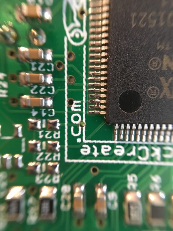
Let’s zoom-and-enhance on that…
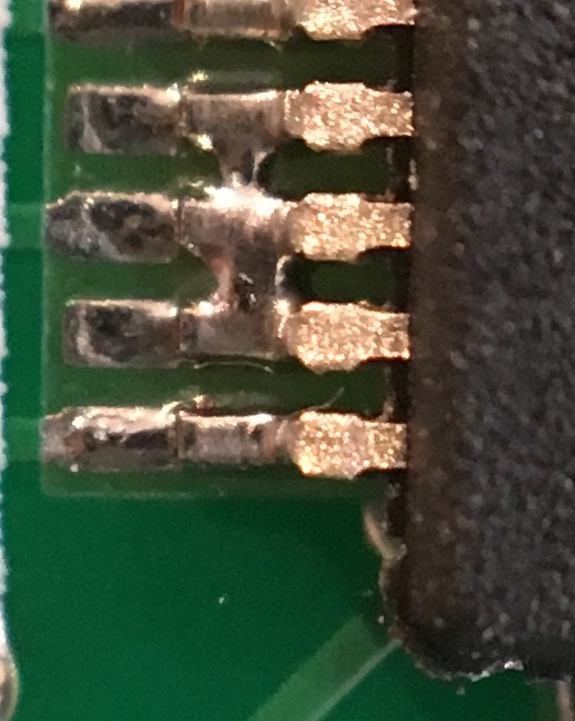
At this point I had a dilemma. Do I risk powering it up and frying something? Do I try to fix it? This is a VQ100 package with pins on a 0.5mm pitch. This is smaller stuff than I have ever soldered. After some thinking, I started by emailing Matthew to see if this would be a problem. Perhaps these pins are unused or are all grounds or something. There are traces on two of them, so they appeared to be in use, but you never know. Things happen in PCB layout. I didn’t get a reply from him (no worries, we’re all busy- I get it) so I took a shot at repairing it.
I started by verifying that there is an actual short here. Sure, it’s obvious in the macro photos, but my 40-something year-old eyes weren’t so sure.
From my previous adventures in hand soldering fine-pitch SMT stuff, I learned that you can usually just swipe over pins with the iron and the solder will glob up in the right places. It wants to be on the pins, and bridges like this are not a stable configuration for molten solder. Unfortunately, I didn’t have any luck this time. I don’t have a fine-pointed tip for my iron, so I was counting on heating the pins being enough to move the solder. It remained stubbornly in place, largely because the clunky chisel tip on my iron couldn’t get the heat to the right spot. I ordered some fine-point soldering tips, and in the meantime considered other options.
I took a couple of swipes at the solder bridges with a dental pick, hoping they were fragile. They were not, and the shorts remained. I didn’t want to get too aggressive with any of these repair measures, because remember that I don’t actually know if anything is wrong. I’m assuming these bridges are a problem, but I may in fact be “fixing” something that isn’t broken and making a mess.
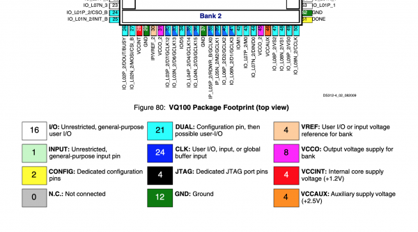
As a final act of desperation, I grabbed the data sheet for this chip on the off chance the pins in question are unused, or all grounds or similar good news. The chip is a Xilinx Spartan 3E FPGA, specifically the S250 variant which has 250k gates and comes in the hobbyist-friendly VQ100 package. You might question how hobbyist friendly a 0.5mm pitch, 100-pin SMT package is, but considering the alternative is a 242-pin ball grid array, well, that VQ100 starts to look pretty damned good.
The solder tips got delayed in shipping, so well, in the words of the great Adama, “Sometimes you gotta roll the hard six”. It was time to apply power and watch the show. Now, this isn’t totally reckless, for a few reasons. First, my power supply has an ammeter on it, so if there’s a bad short, I’ll see it in short order. Second, never underestimate the power of the finger test. If you suspect shorts, put your fingers on everything. Anything shorting will be hot, I guarantee it. The laws of physics are simple here- excess current must be dissipated, and that happens via heat. You might think that the components will destruct too quickly for the problem to be detected with such primitive measures, and sometimes that’s true. However, most of the time, the truth is these parts are tougher than people give them credit for. I’ve seen old TTL chips sit in a dead short for 20 seconds or so, and they were still fine when I finally noticed and corrected the problem. Modern chips are tougher still and tend to have safeguards in them for ham-fisted stunts like this. I’m not saying this is the best idea, but I am saying it is not the worst idea.
Power? Go, flight.
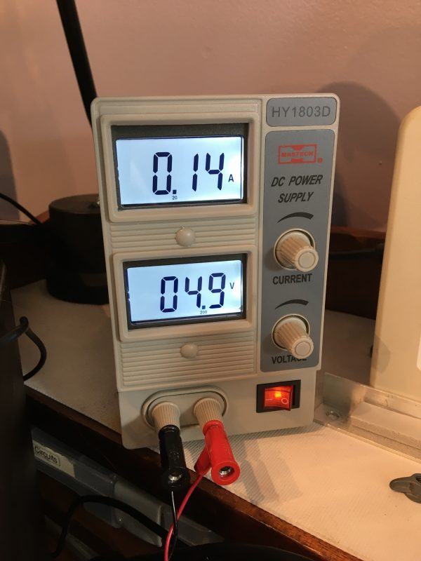
No smoke and reasonable current draw! This is good news! Perhaps those IO pins are not in use, or perhaps they were only used for programming the device, and shorts don’t matter for normal use. It’s possible some internal function of the device isn’t working because of the shorts, but hey, those fine-point solder tips will get here someday.
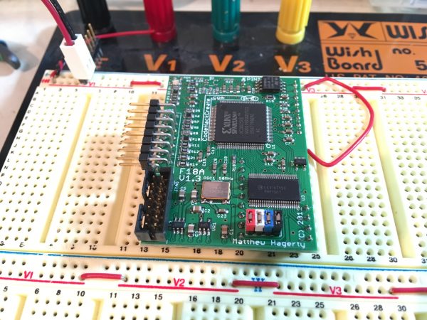
Okay, time to take this to the next level. I don’t have the device hooked up to a computer, of course, but I reasoned that it might be designed to show something on the screen, even when dead-headed. Only one way to find out!
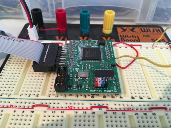
I needed to figure out what the minimal configuration of inputs might be to make it do something. Remember that this device is a drop-in replacement for the TMS9918A, so that‘s the datasheet I have to go next! Luckily, Texas Instruments produced a very nice technical manual for this chip, of which good scans are pretty easy to find online. What’s interesting about the F18A is that it only implements a small fraction of the pins on the original chip. Basically just power, a couple of control signals, and the CPU data bus. This is because, as I mentioned earlier, it doesn’t use the TI-99’s outboard VRAM the way the 9918A did, and the device is not memory-mapped the way a 6502-targeted accessory would be. This all means it has surprisingly few pins. It does have a reset pin which is active low, so I tied that high.
I powered up the device with my monitor connected and got a black screen. However, the monitor did sync, so a VGA video signal was present. Could it be as simple as supplying a proper reset pulse? I briefly grounded the reset line, and…
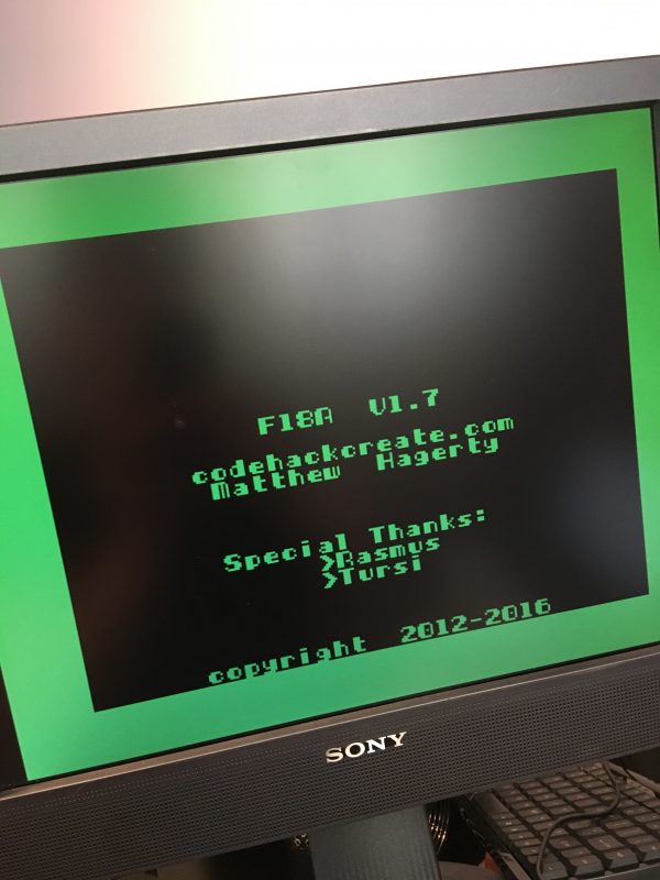
Result! It’s producing amazing looking video with nothing but power and ground. Everything is green, but I’m not sure if that’s a bug or just how the splash screen is. All I need to do now is figure out how to interface Veronica to it, and write all the software. Wait… that’s not going to be easy… well, I’ve never been known for doing things that are easy, I guess. Why start now? Stay tuned, Veronica fans. Things are about to get nuts.
w00t!
You might also look at the Rockwell R6549 CVDG. It’s really meant for Videotex systems — but it may be tweakable for what you want. It outputs RGB+HSync/VSync as well, and is readily obtainable from the usual shifty Far East eBay sellers. The *good* news is that — at least according to the noises I’ve heard — these are faithful and functional reproduction hardware, not NOS — someone in China has a factory making /proper/ clones with the Rockwell logo stamped on top.
…or, not.
If you change your mind, 6502[dot]org has the datasheet.
One more thought. If you wanted to /upgrade/ a bit, the Yamaha V9938 is the successor chip to the V9918 series — and those (the Yamaha chips) are fairly available on eBay. Pricey tho.
YAY! Veronica is back in action! Maybe I’m jumping the gun, but I’ve just submitted this to Hackaday. AND I’m goint to submit every step of the process too. I’m obnoxious that way.
Aww, thanks! 😀
Freaking awesome! I’ve looked into an F18A for my JCM-1 Project, but alas, they’re like hen’s teeth. I’ve decided to roll my own NTSC generator. Wish me luck!
If you’re willing to go NTSC, I think the original 9918A could be a really good choice. You can find them on eBay (strip a TI-99/4A if you have to, they made millions of them and are cheap). It spits composite video right out of the chip.
Yay! Veronica is back, and she’s a sight for sore eyes. 🙂
Nice to hear there’s an FPGA clone of the TMS9918, that might have interesting implications for some of my own future projects. Some part of me was considering doing an FPGA version of my own; that part has now been freed up.
I might have cleared up that short by heating a paperclip to melting point with the gas flame from the stove, or something radical like that. Glad to see it wasn’t even necessary.
Looking forward to seeing more of this.
===Jac
I recommend emailing Matthew and asking for the Mark 2. Maybe if enough of us do that, he’ll be motivated to make the time to finish it! 😀
Us Amiga people got so much gloating in back in the mid-80s that we probably can still coast on that without having to flip tables now.
In my experience, what you’re facing is the perfect application for solder wick, even (or perhaps particularly) with a coarse tip. That stuff (with a bit of liquid flux) will suck up so much solder I sometimes feel compelled to go in and add a little because it looks like the pad’s completely empty.
I considered wick (and I also have a desoldering gun), but I’m concerned about removing too much solder and having to try and put it back. We’ll see- it’s working for now, so I’m leaving well enough alone. 🙂
Hooray for Veronica!
After graphics (I hope you have a dual-monitor Veronica at some point during testing), any plans for sound? I imagine possibilities range from interfacing with a chunky old sound chip to building a tiny analogue synthesiser, complete with authentically awful burps and farts.
I have thought about sound, yah. I was thinking maybe an Atari POKEY chip. They are much easier to get than something like a SID chip, which go for crazy money now that the cool kids have discovered them.
Could the failure to remove solder bridges be a case of not enough flux?
The main problem was that I wasn’t able to get the large chisel tip on my iron physically into the right place.
The guy who developed the F18A probably picked that colour scheme to match the TI99/4A. Your chip is more than likely okay.
Good to know, thanks! I hope we’ll find out for sure soon. 😀
I think Veronica might be my favourite project of yours. I remember when it first got started and the presentation video (was it at K-Fest?). Anyhow, I’m glad you’re working on her again. It’s been an inspirational project for sure.
Aww thanks! I did a presentation at K-Fest, yep! I did another one at the first Hackaday conference (the same talk, basically).