From boat anchor to booting game.
When Johnny arrived at my house, he was a 325lb plywood boat anchor. He didn’t boot up at all. The main reason is that the power driver board had been removed from the machine. The reason for that was that the seller had another game that needed it, so he sold the broken one to me along with poor Johnny here, in the hopes I could fix it.
My first step was simply to see what the broken board was doing. I needed to know the symptoms before I could know what to start diagnosing. The power driver board has a very large number of connectors around the edges of it, because it supplies all manner of currents and voltages to every part of the machine. As you can see from this page in the manual, there’s a lot going on.
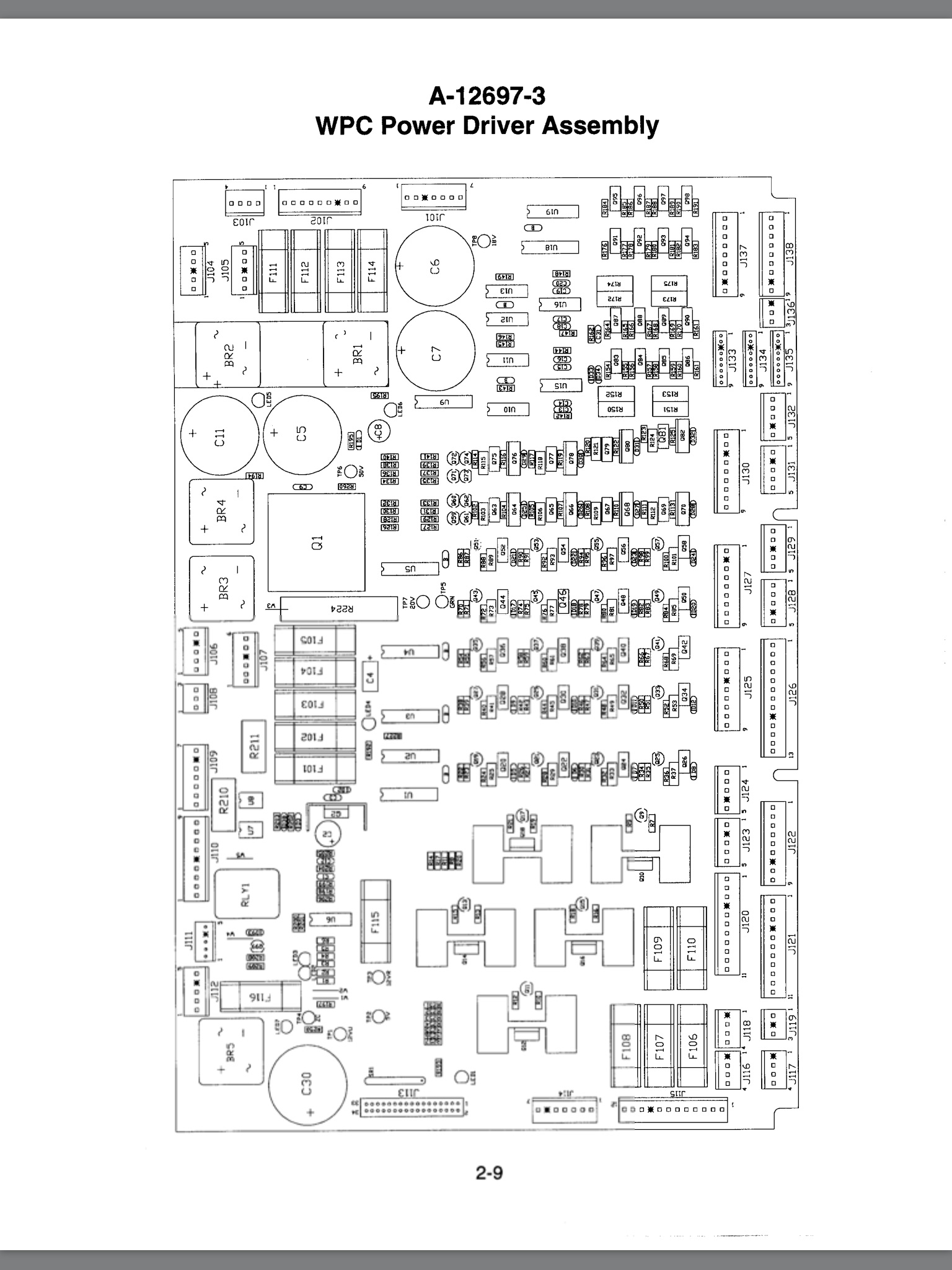
To give you an idea of the madness of a pinball machine, this board supplies 70VDC, 20VDC, 18VDC, unregulated 12VDC, unregulated 5VDC, regulated 12VDC, regulated 5VDC, 6VAC, and possibly others that I’m missing. Furthermore, some subsystems have their own regulated supplies. It’s a Willy Wonka Candy Factory of currents and voltages in there. To make things more confusing, this is a general application board used in all Williams games of the era, so not all connections and components are used in every game. As we’ll see though, that may work in our favor.
So, I installed the board in its position in the back box using the provided screws, and proceeded to hook up the many connectors. Nothing was labelled of course, so there was some potential for adventure here. For most of them, there was either only one place it would fit within reach of the harness, or the connector was keyed. This last part becomes important. Williams keyed these connectors in a very simple way. They used a header that was one pin wider than they needed, then broke off an arbitrary pin, and plugged the matching hole in the connector with plastic. By throwing away a different pin in each connector, you get idiot-proof connections without having to buy a lot of special connectors. Again, these machines were designed to be serviced, so a lot of thought went into things like this.
Everything was going fine until the final two connectors.
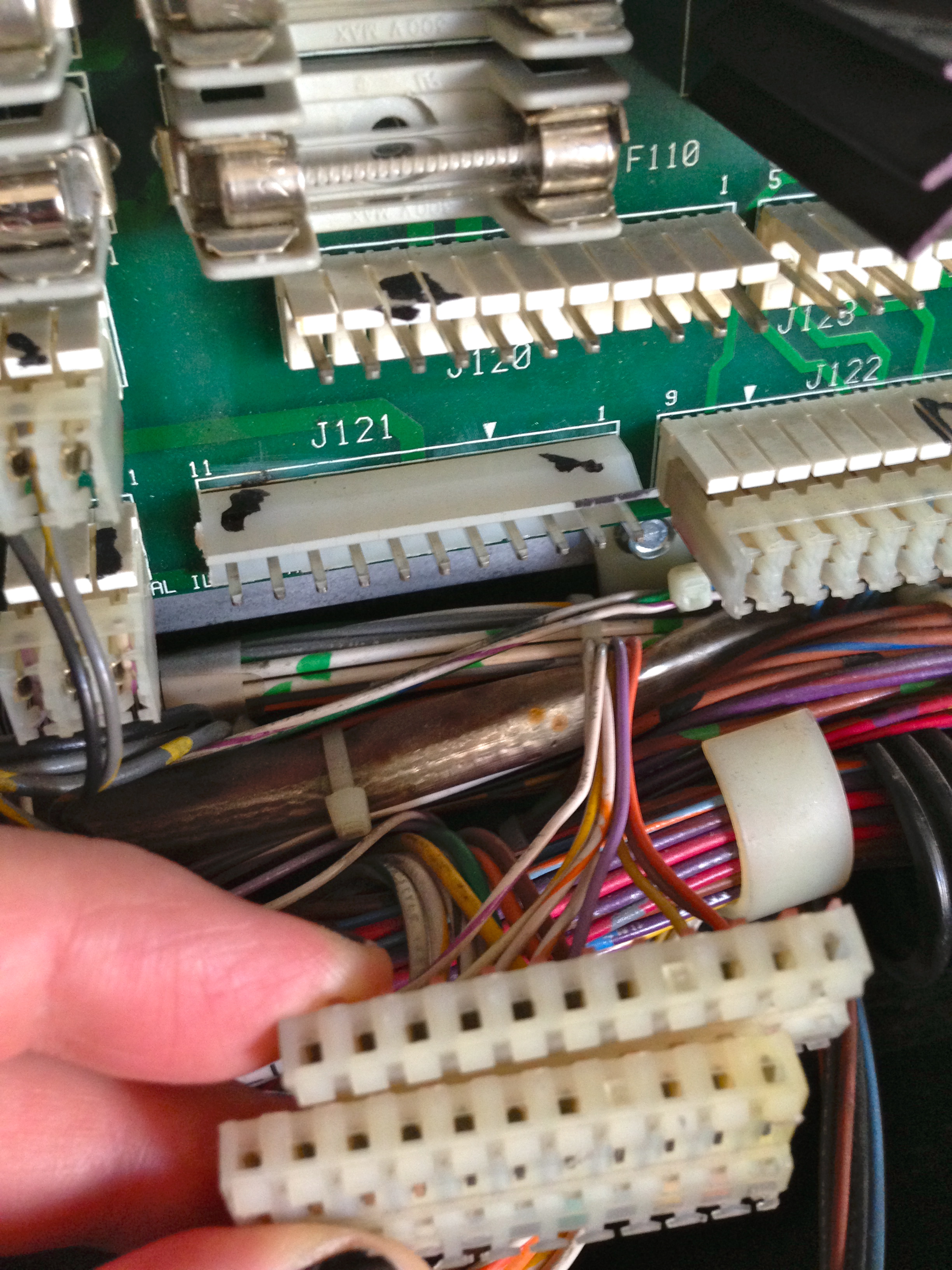
After studying the schematics in the manual, and trying a few things with the harnesses, it was pretty clear that the lower of these two connectors was supposed to mate to J121. Baffled, I spoke to the seller to see if he knew anything about the history of this board. This would become my first lesson in The Secret Lives of Pinball Machines. Like an old car, these machines have been passed from person to person over the years, and each owner has done various things to them- some good, some… colorful.
In this case, the power driver board I was given came out of a different machine- a Whitewater. The previous owner of the Whitewater machine had replaced J121 in his machine, but had replaced both halves of the connector. In doing so, he didn’t bother recreating the proper keying of the eighth pin, as shown in the photo above. So this board fit perfectly in his Whitewater, but mine still needed the proper Williams keying. So what’s the easiest way to re-key this header so the connector will fit?
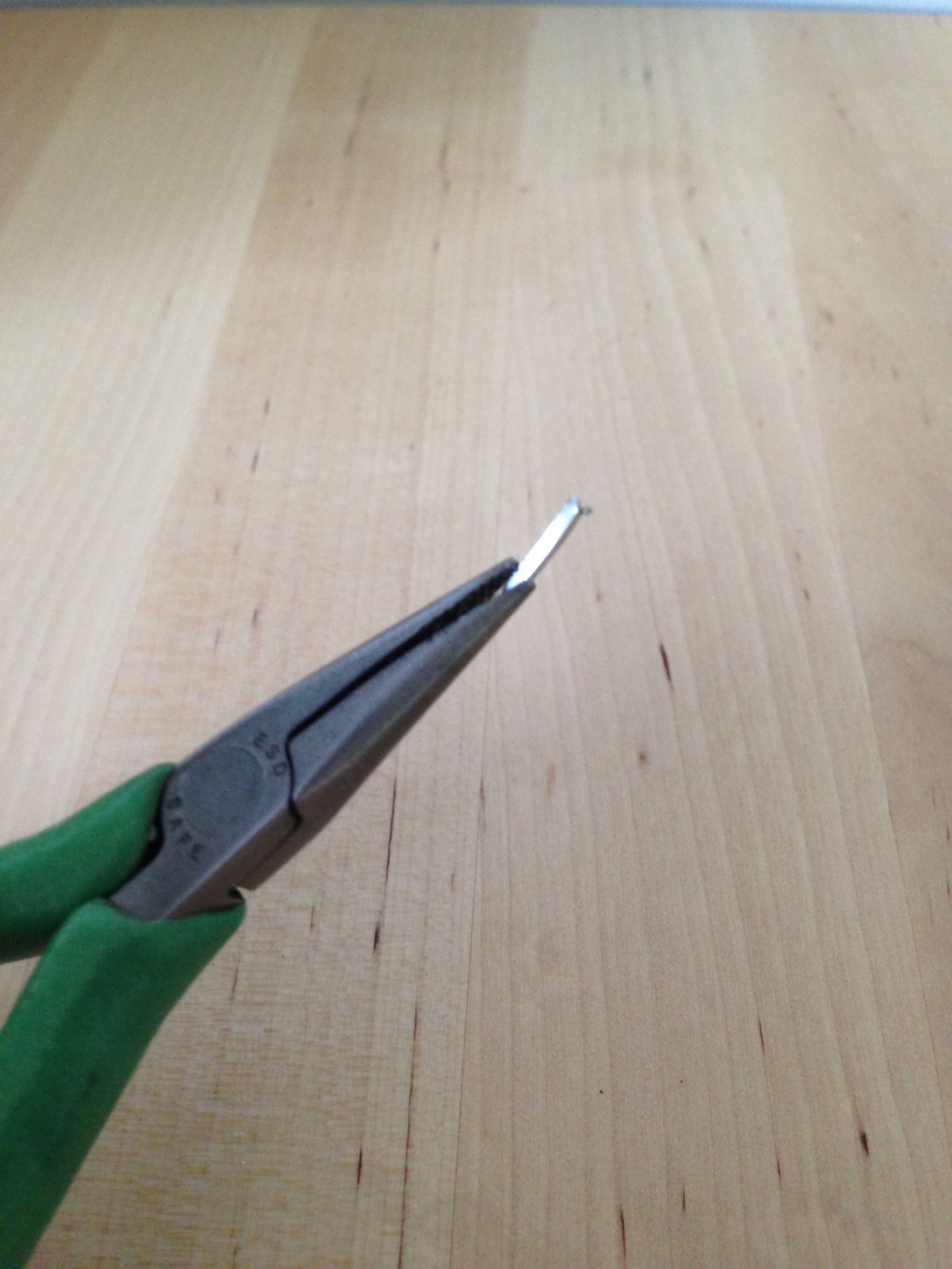
Thus marks my first official hack on this machine, although perhaps it doesn’t count, since I’m actually returning the connector to its correct state.
With that quick fix, the connectors all went in the right places, I held my breath, and flipped the switch.
Huzzah! But wait- wasn’t this board supposed to be broken? I ran it through all the tests of lights, solenoids, flashers, and other things needing power, and it all checked out. So either the seller was mistaken about this board being damaged, or by chance Johnny is using different driver elements than the Whitewater game it came out of. Remember that these boards were used in a lot of games, so not every part is used all the time.
Huzzah again! Well, let’s say huzzah-ish, because while it fires up and mostly seems well, the display (and accompanying bong) tells us there are problems.
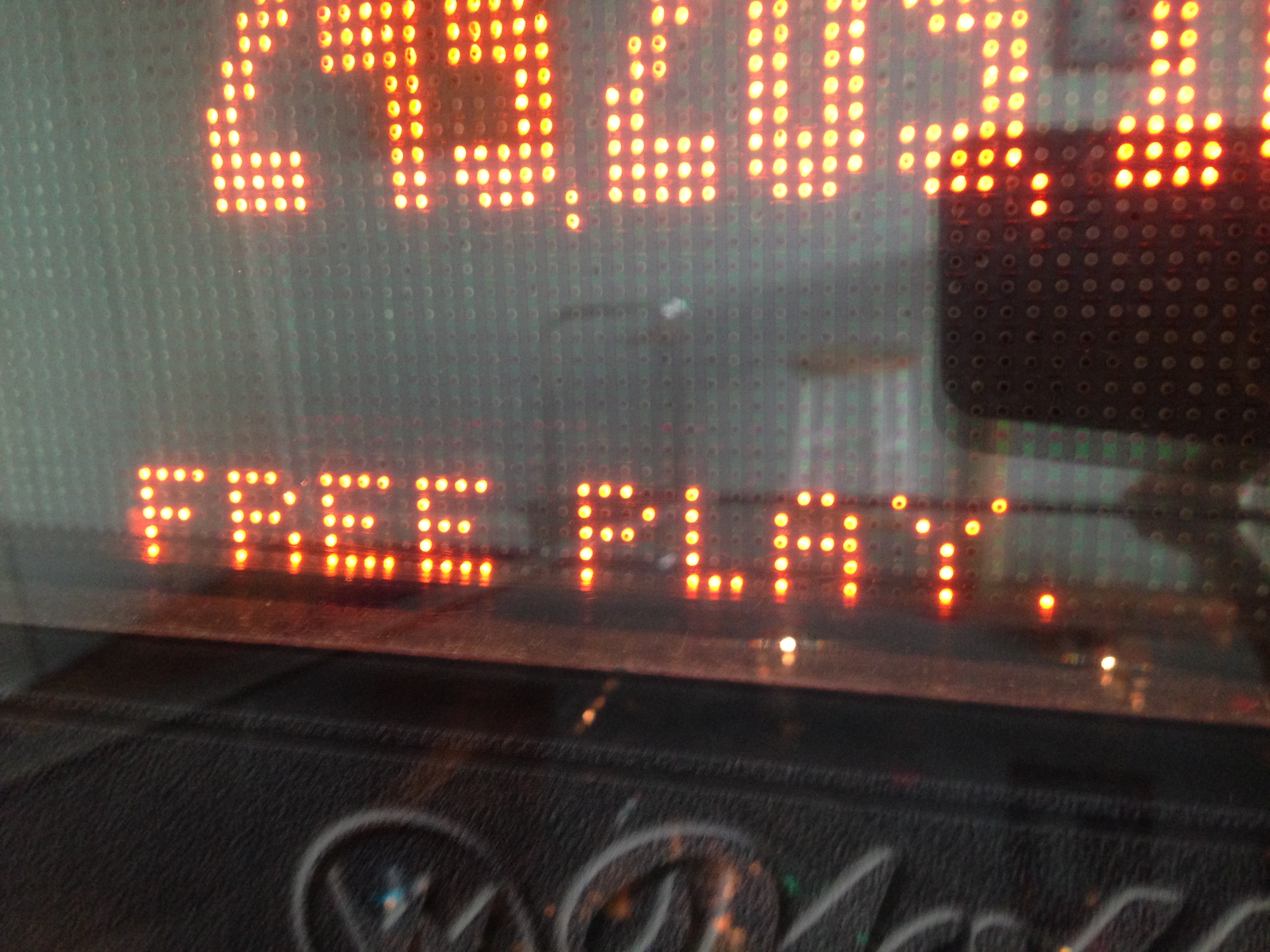
To see what those problems are, we go into the test report using the service controls inside the coin door. Details of this process are covered in the manual.
Credit Dots are caused by switch problems. If the game hasn’t seen any activity from a given switch for a long time (say 30 or 40 balls), it assumes the switch is bad and flags it. This is a great feature of modern games, considering they have many many switches.
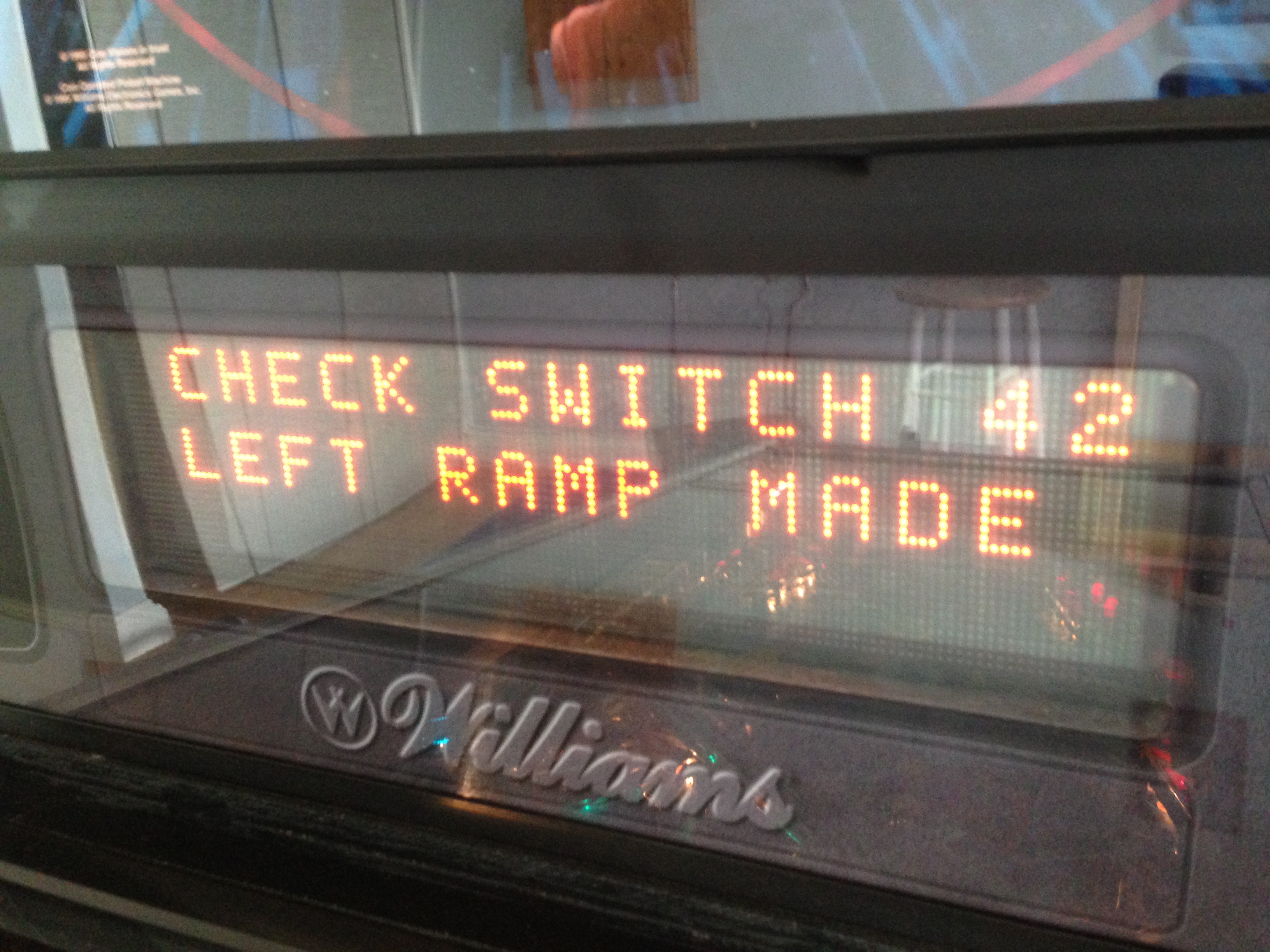
After locating the problem switch, we go into single switch test mode. Here, the machine simply watches the switch in question and tells us when it is open or closed. My first flagged switch, #42, was actually working correctly. Activating the switch once by hand cleared the error. If you’re a lousy player and playing a lot of games (like me), it’s possible you just aren’t hitting all the switches with any regularity. In that case, the credit dot is telling you to get better at pinball.
A second switch was flagged, however. #55, Right Ramp Made. I knew for a fact I had been hitting this ramp, so something legit seemed to be wrong. So I went into test mode on that switch next.
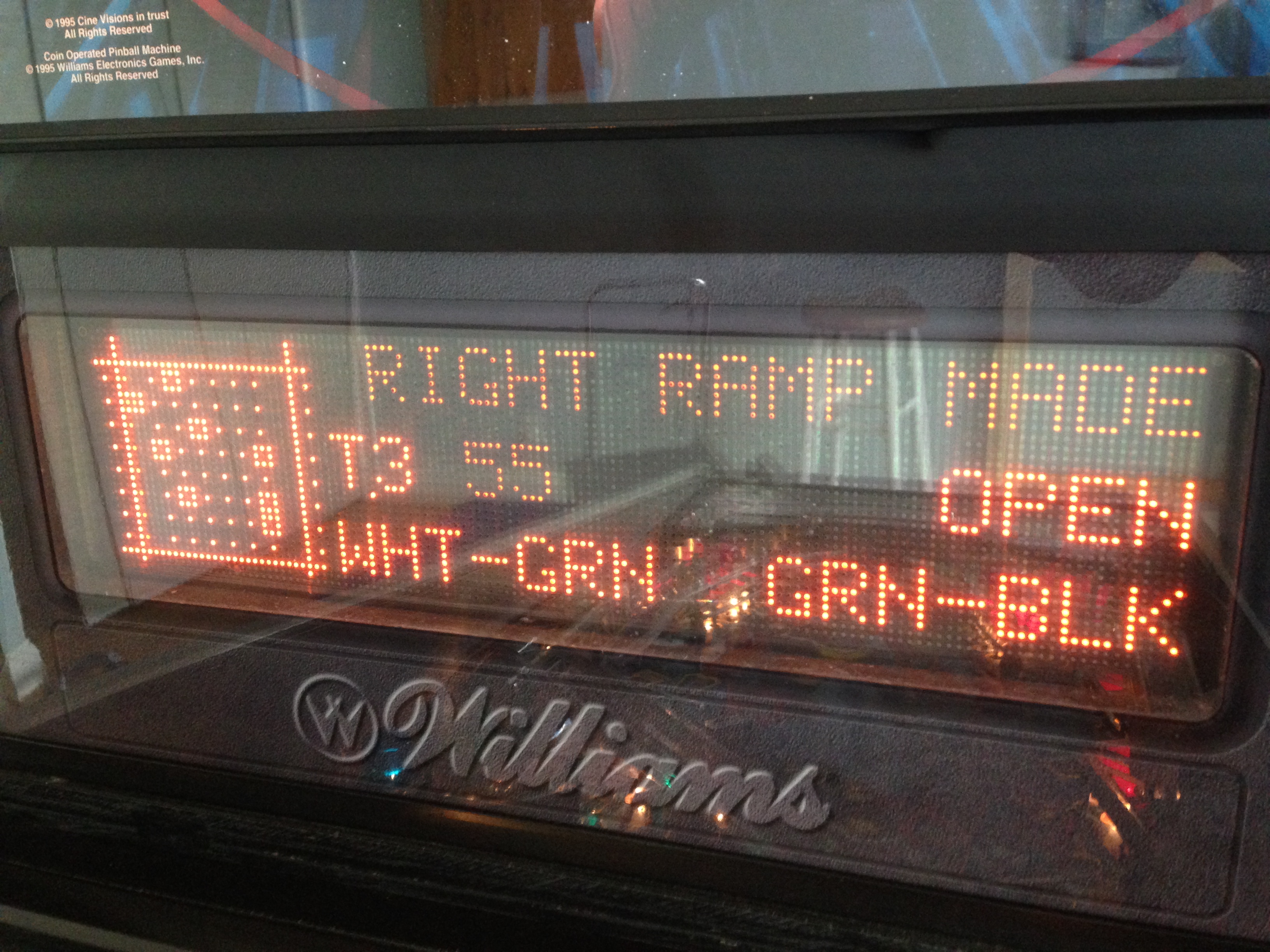
To test the switch, always use an actual pinball. Roll a ball over, through, or under the switch to see if it activates correctly and consistently. Don’t use your finger, because the ball may react differently. Also, try to roll the ball at the same speed it would travel during gameplay. Speed can affect how the switch activates.
After clearing those two switches, the credit dot went away and I was back in business. Now for some things I found during my initial cleaning and inspection.

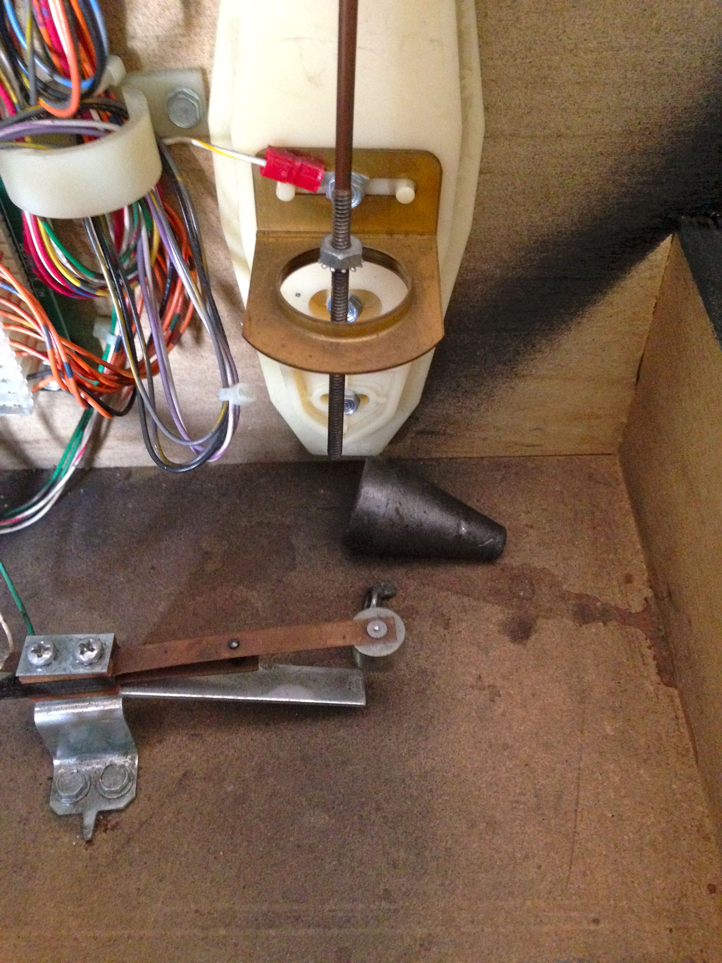
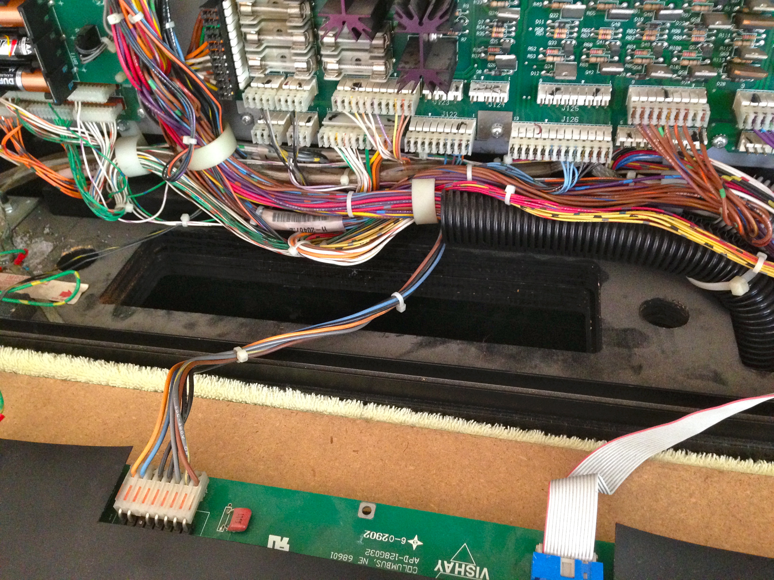
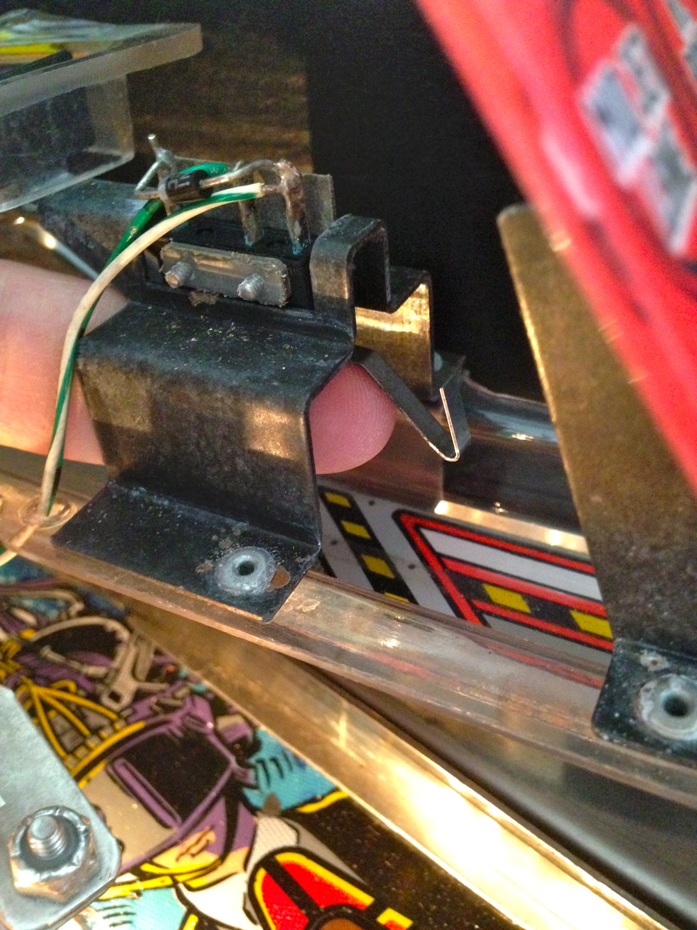
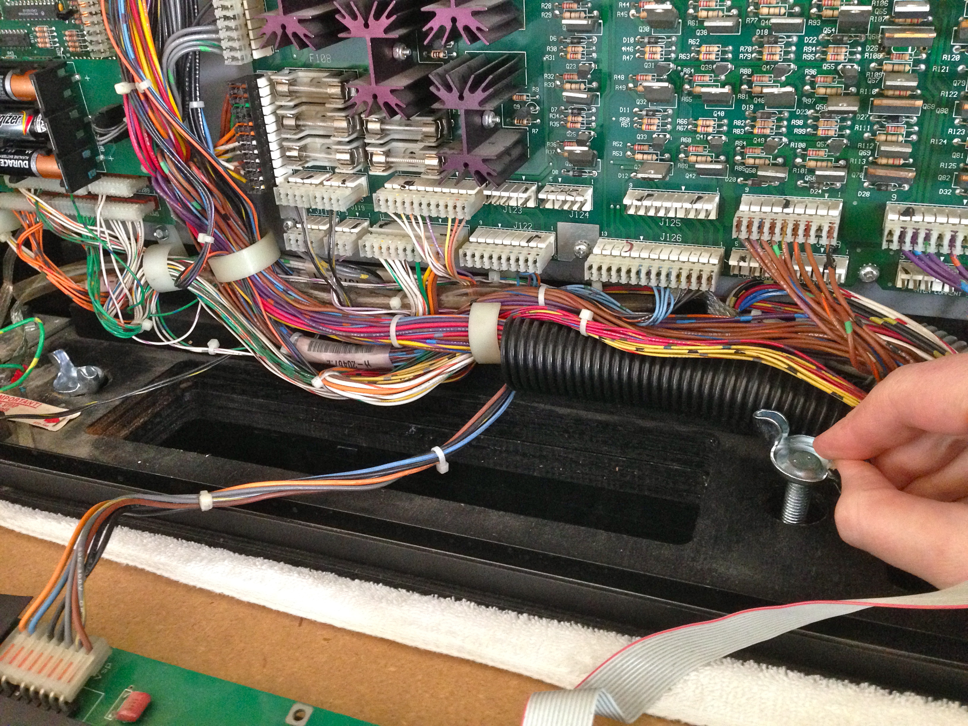
In case you weren’t aware, the back box hinges up and down for transport. In the up position, there’s a small latch on the back to hold it upright. However, this is not much of a clamp, and it isn’t supposed to be relied upon. The two holes on either side of the square opening in the above photo are for wing bolts that hold the back box firmly in place. These bolts can be ordered from places like Marco Specialties, so this was an easy fix. Without those bolts, there’s only a flimsy clamp preventing the entire back box from coming crashing down. Those bolts are very important! I’m shocked to find them missing, and even worse, the latch on the back box isn’t in very good shape. There hasn’t been much holding Johnny’s head up for a long time (except possibly his own sense of self-worth).
So, with all these basic fixes done, I was able to actually play a few games. Hooray! Pretty soon though, new problems started to appear. It’ll be a while before we get all the kinks worked out of our old boy here. More on that next time!
This is a real treat to read! All this backstory on how well pinball machines are designed and setup for easy (ish) repair work is fascinating.
I’m surprised to see a set of 3 AA batteries hanging out in one of those pictures. For saving highscores would be my guess, but it’s still interesting to see in a board where so many other connections and components look a little more custom.
Thanks! These machines really are fascinating. They were completely custom computing platforms with a lot of interesting quirks that few people outside the pinball world appreciate. These Williams machines, for example run on a custom single-board computer based on the Motorola 6809, with a custom operating system and even some DRM. We’ll be diving into all that in a little while.
The batteries are there to save scores and settings. These machines have massive configuration menus, where nearly every element of scoring, gameplay, display, and cost structure can be customized by the operator. The idea was to allow them to gather data and adjust whatever was needed to maximize profits from the machine. If increasing bonus multipliers on the pop bumpers resulted in an extra dollar every 20 players, the operator could track that and make the change. It was both art and science to run a successful arcade.
+1
The built-in diagnostics in particular I find fascinating. It’s so interesting to see all the built-for-repair aspects of it, unlike so many modern things that are built to be thrown away and replaced.
Thanks for sharing, and keep up the great work!
I admit to having a geek-out moment when I saw the wire-color labeling information in the switch diagnostics. I thought that was the coolest shit ever, and I knew I had to blog out it. I don’t get out much, though. 😉
Getting out is overrated. At least when you’ve got awesome things to tinker with 🙂
I agree; the wiring colour-code stuff in the diagnostics just amazed me! I shows that the manufacturer planned everything properly and really thought through the needs of the repairers. And they remembered to tell the software engineers!
Hi Quinn,
it would be great if you could make the pictures link to the high-res. versions as in your blog posts about Veronica. Are there any schematics for this puppy available online? Keep up the great work!
Oh! I’m surprised to see they aren’t already doing that. I didn’t think I had changed anything about how I’m posting the photos. Let me look into it.
So, it looks like this stopped working sometime in early December. Most likely a WordPress update changed the default image posting behavior, since my workflow has remained the same for years. I’ll try and mess with the settings and see if I can get this working again.
Okay, so indeed the default WP behaviour changed and I didn’t notice. I need to go back and change the options on each photo for the past few posts, but the latest post should now work. Thanks for bringing this to my attention- it’s greatly appreciated!
Regarding schematics, yes, they are available. There are two sets- the service manual which comes with the machine has block diagrams of the major systems, and documents all the harnesses and connectors. It has also has board layouts and component details of every board. For actual schematics of the traces on the boards themselves, they released a separate Schematics book for each board system they used.
Both books are generally available free online in PDF form, although I don’t know the copyright state of those documents.
Quinn,
Congrats on resurrecting Johnny up to first boot! You’re right about the parallel with used cars. There’s a lot of: What Were They Thinking? But sometimes there is a fix/hack for safety, reliability etc. that just makes sense like extra grounding straps. I’m sure you’ll err on the side of reason than ‘historical correctness’ or expediency…
Those displays are cool, VFD if I guess right. Probably where that 70vdc is going.
Good luck!
Crawford
The dot matrix display is a whole other can of worms, in fact. It’s actually plasma, and has its own power driver board. It takes 80VAC and 100VAC straight from secondary windings on the main transformer, bypassing the rest of the machine’s power supply. The DMD driver then sends 125VDC, 113VDC, 5VDC, 12VDC, and 62VDC to the plasma display. There’s a special harness just for all these voltages. What it does with all of them, I couldn’t tell you off the top of my head. 8)
I expect to do a post on this display at some point, because mine is exhibiting a few issues.
Maybe it’s for the different intensity levels each pixel can have?
You could be right- there are 4 voltages, plus 5VDC for the logic.
The DMD has 4 “gray” levels for each pixel, and I thought I read somewhere that this is done with pulse width modulation, but I’m not certain. I’m definitely curious to dig into this thing further.
A pixel needs a high voltage to ionise, but then a lower voltage will keep it on. For a matrix display, you need to be able to switch pixels in the current row on and off as required, and keep all pixels that aren’t in the current row in their previous state (so they need a voltage above the lower threshold but below the higher one), despite them seeing the column voltages that are turning pixels in the current row on and off. I don’t fancy working out the details, but it wouldn’t surprise me if that’s where the different voltages come from. LCDs do something similar.
It might be possible to control brightness by changing the current, but PWM will be a lot easier and more controllable.