Somebody give this man a hand!
You just knew I was going to make that joke at some point, so we might as well get it out of the way in the subtitle, right? Johnny Mnemonic’s signature feature is the “cyberglove”. Among owners, it’s more commonly known as “the infamous hand”. When working, it’s a ridiculously cool feature. When it isn’t working, the game is about 60% less fun.
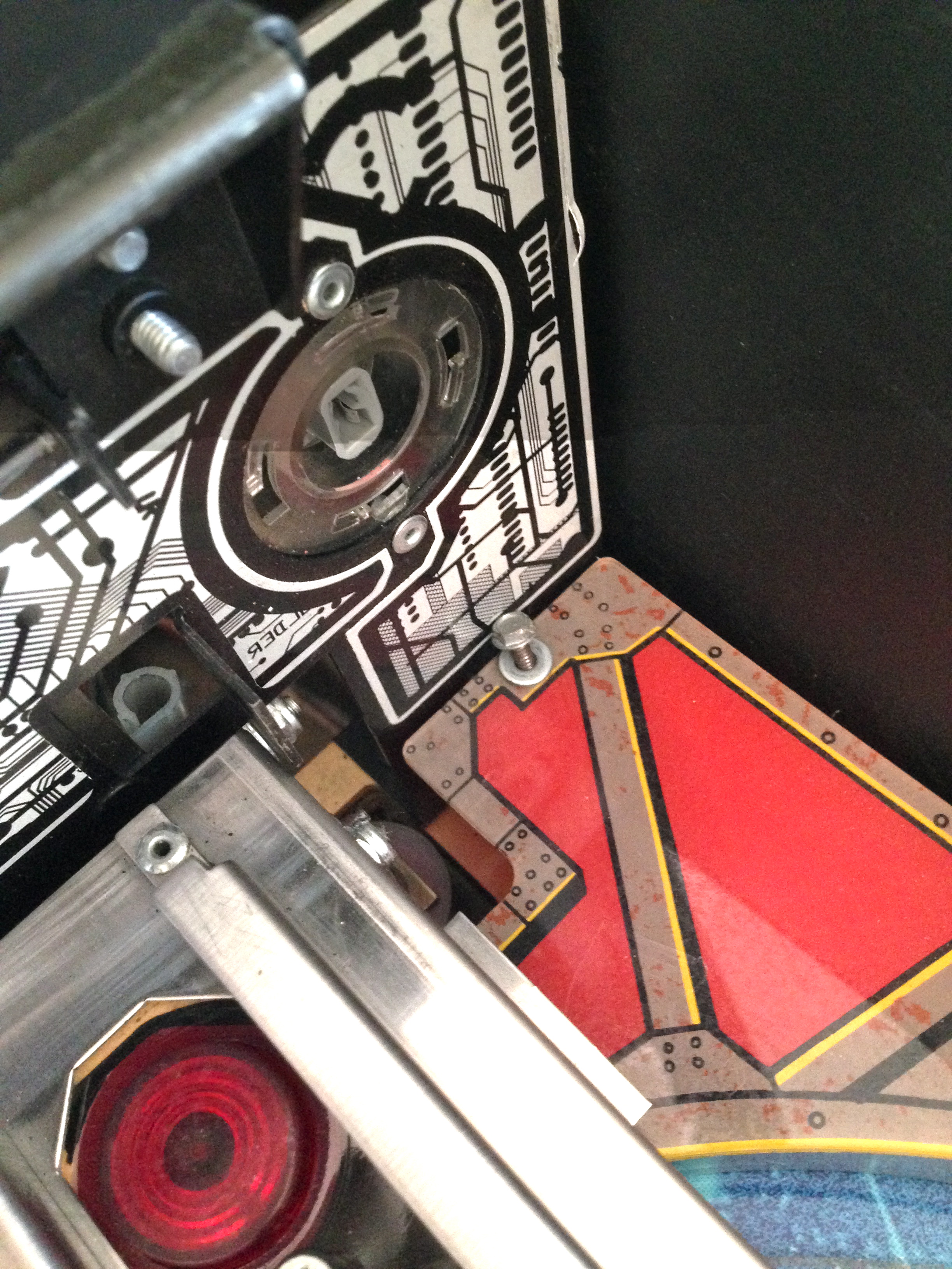
When the player shoots a ball up the middle of the play field, it falls into a pocket and lands on a piston. A very beefy solenoid kicks the ball straight up about 8 inches, where it is caught by a strong electromagnet (hiding under a plastic glove prop from the movie). This magnet holds the ball, and the player is then given control using the flipper buttons. The glove moves on both X and Y axes, and the goal is to choose one of nine spots on the “cybermatrix” to drop the ball onto. There are various strategic gameplay reasons to choose different spots, but I won’t go into it here. Suffice it say, the player is in control of a robotic hand that catches a very heavy steel ball shot into it from a long distance. It’s insanely great. When it works.
It often doesn’t.
That lovely sound it makes while moving towards the camera is what ultimately pushed me over the edge to start this rebuild. Prior to this, the hand had been working, but was showing some signs of trouble (occasional missed catches, sagging under the weight of carrying a ball, and slow operation).
The mechanism that does all this is pretty complex, and wears out sooner or later. After just a few hours of play on my Johnny, the hand was starting to act up. Rather than messing around addressing symptoms here and there, I decided to rebuild the entire assembly. Once rebuilt, it should run smoothly for years to come. Arcade operators tended to do as little as possible to get the hand working again, and it often sat broken for long periods. That means the hand on any given Johnny is usually in need of a total rebuild like this. So let’s get started!
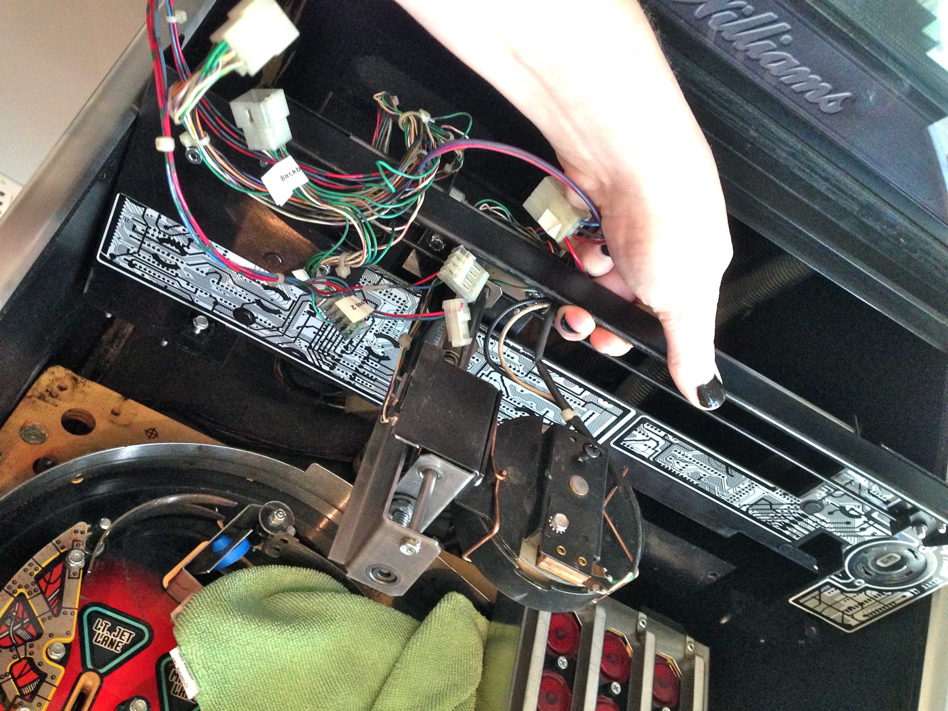
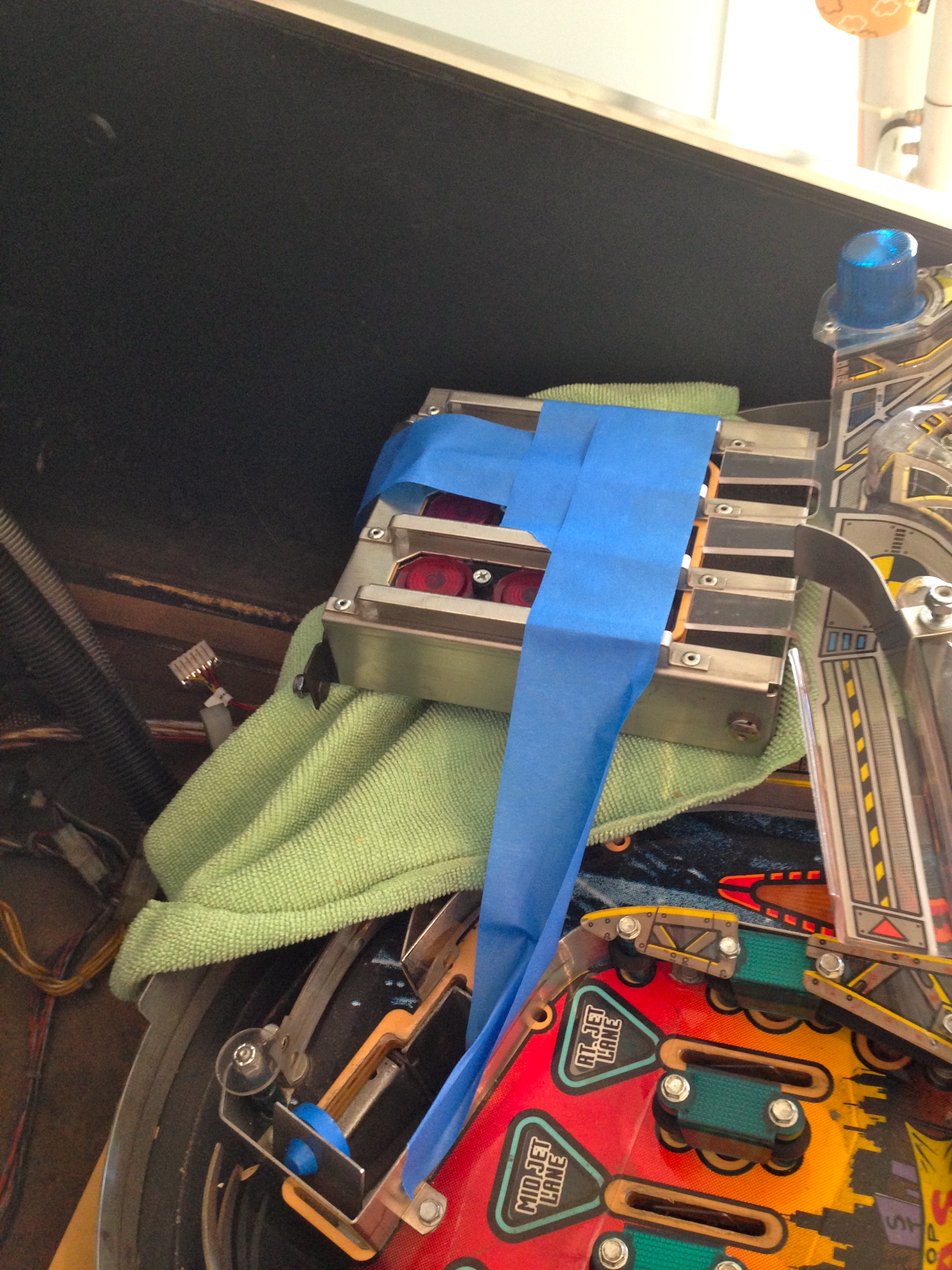
The general consensus is that the easiest thing to do is remove the entire backboard assembly from the play field. After doing it, I agree this is the way to go. Most of this job is done with the play field lifted and sitting on the supports. I needed to hinge it all the way vertical a couple of time to access some areas. This whole process is a bit time consuming, but there’s nothing difficult about it, and basic hand tools are all you need.
The first step is to disconnect every electrical connection to the hand assembly.

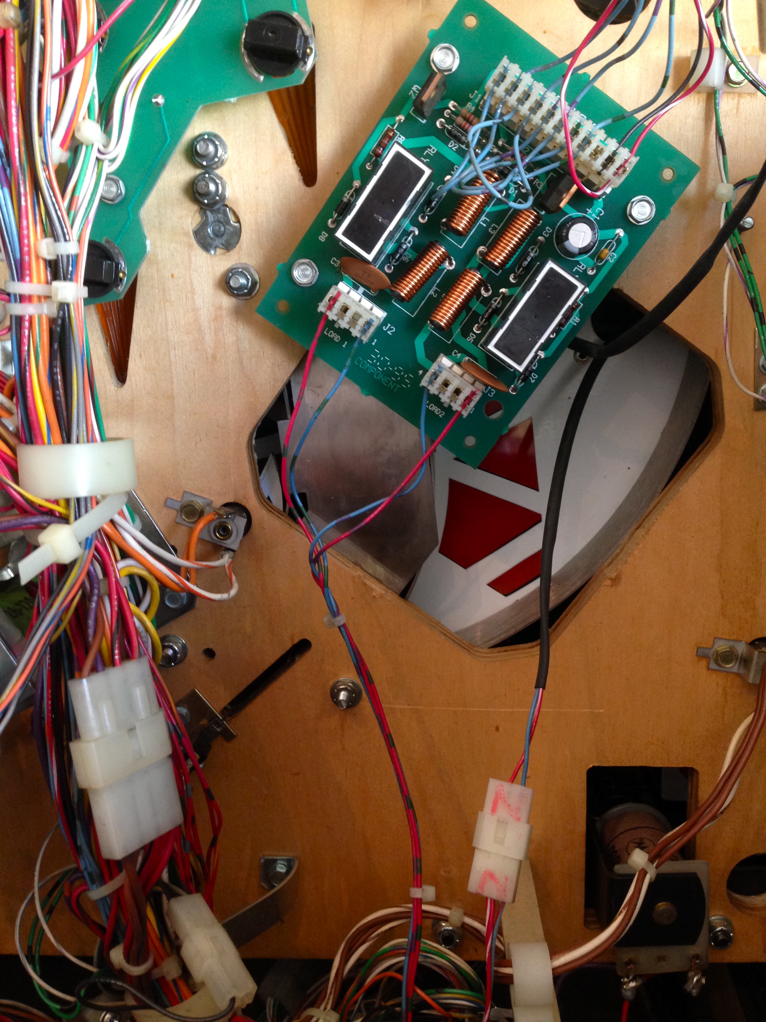
Next, disconnect anything that is attached to the backboard. There are a couple of plastics, and the cybermatrix unit.

Now we’re ready to unbolt the hand assembly itself. There are six nuts that hold it from underneath.

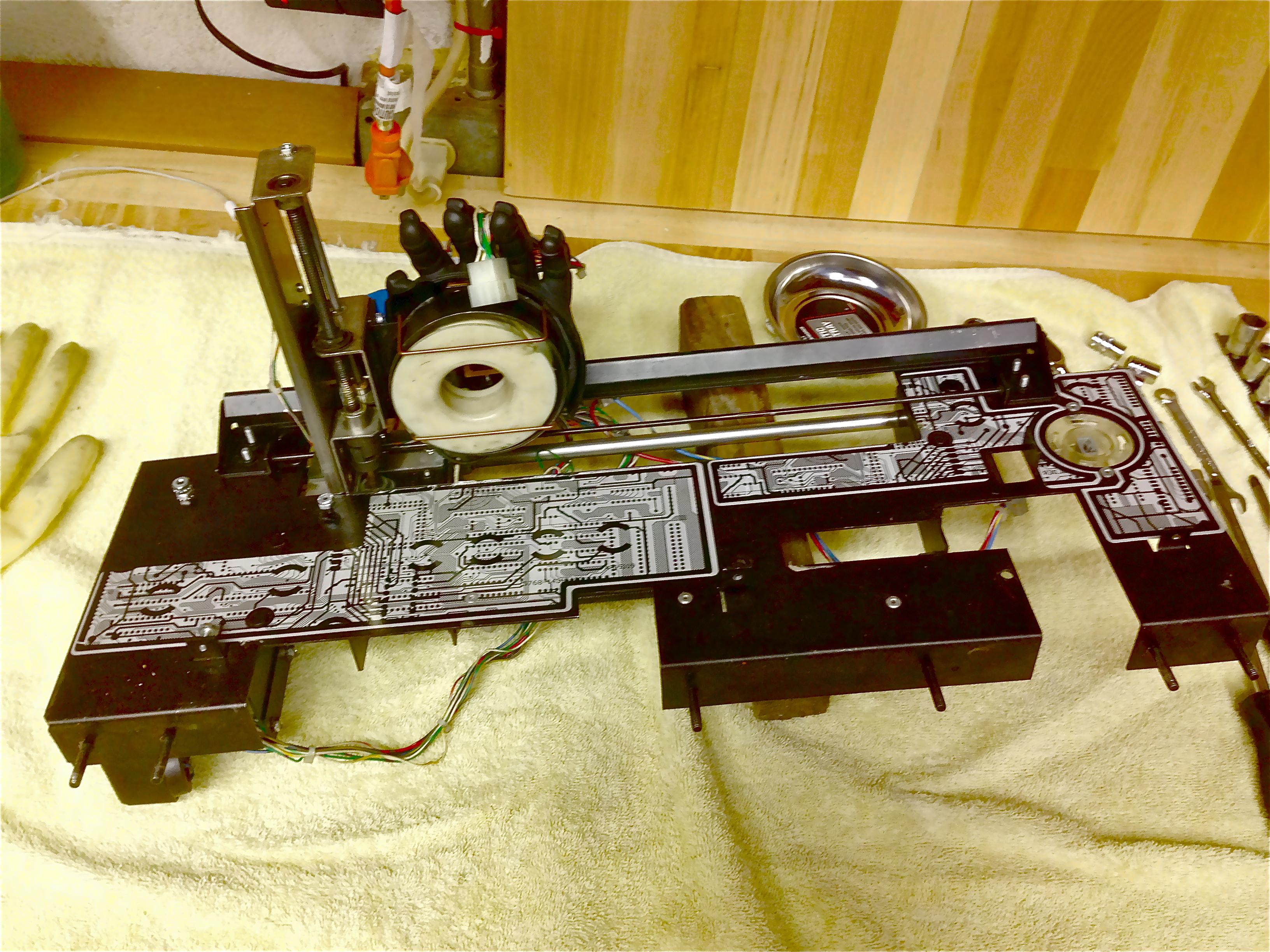
Now that we have the assembly on the bench, the job is tremendously easier. Trying to do this in-situ on the machine would be a special circle of hell reserved for politicians and people who design British cars.
The main targets of our rebuild are the axis nuts, the bearing surfaces, the gearboxes, and the electromagnet. At this point, I simply took everything apart, and cleaned as I went. Some previous operator or owner had gotten a little carried away with machine oil, and there was a lot of slime and crud on things. Some Simple Green and a few shop towels go a long way. A clean mechanism is infinitely nicer to work on than a dirty one.
My strategy was to break the assembly down into major components, then work on each in turn. The wiring on mine was somewhat of a rat’s nest that couldn’t be separated cleanly. It looks like someone has repaired this harness in the past, but they routed wires in such a way that the harnesses are forever braided together. That meant I had to keep all the assemblies close together in sort of a “blob” on the bench as I went along.
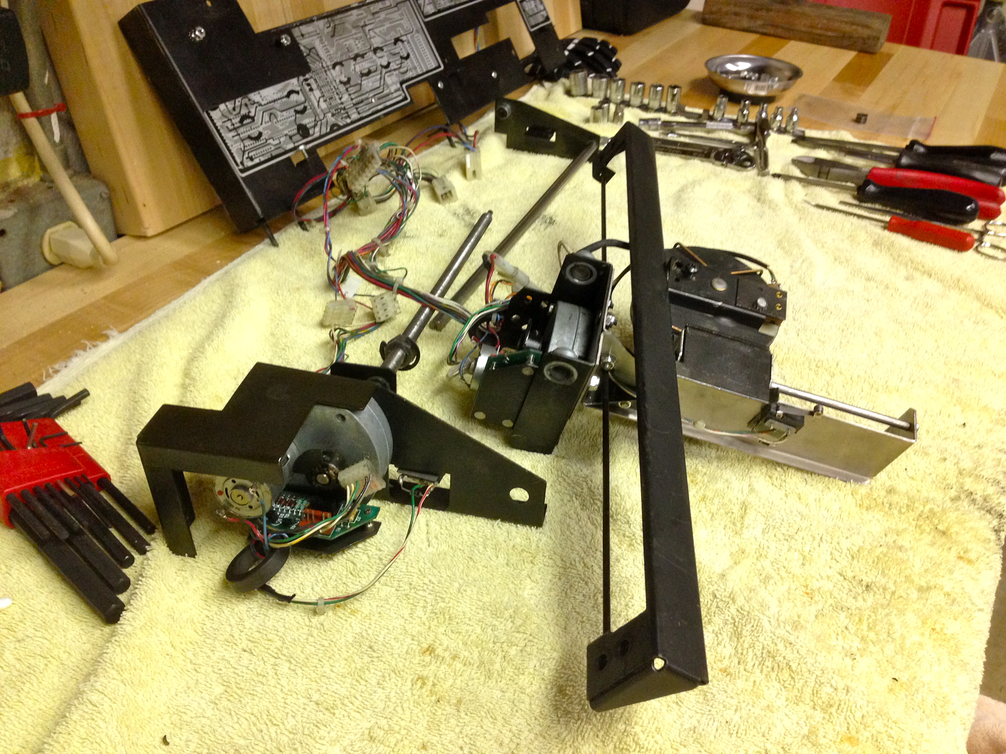
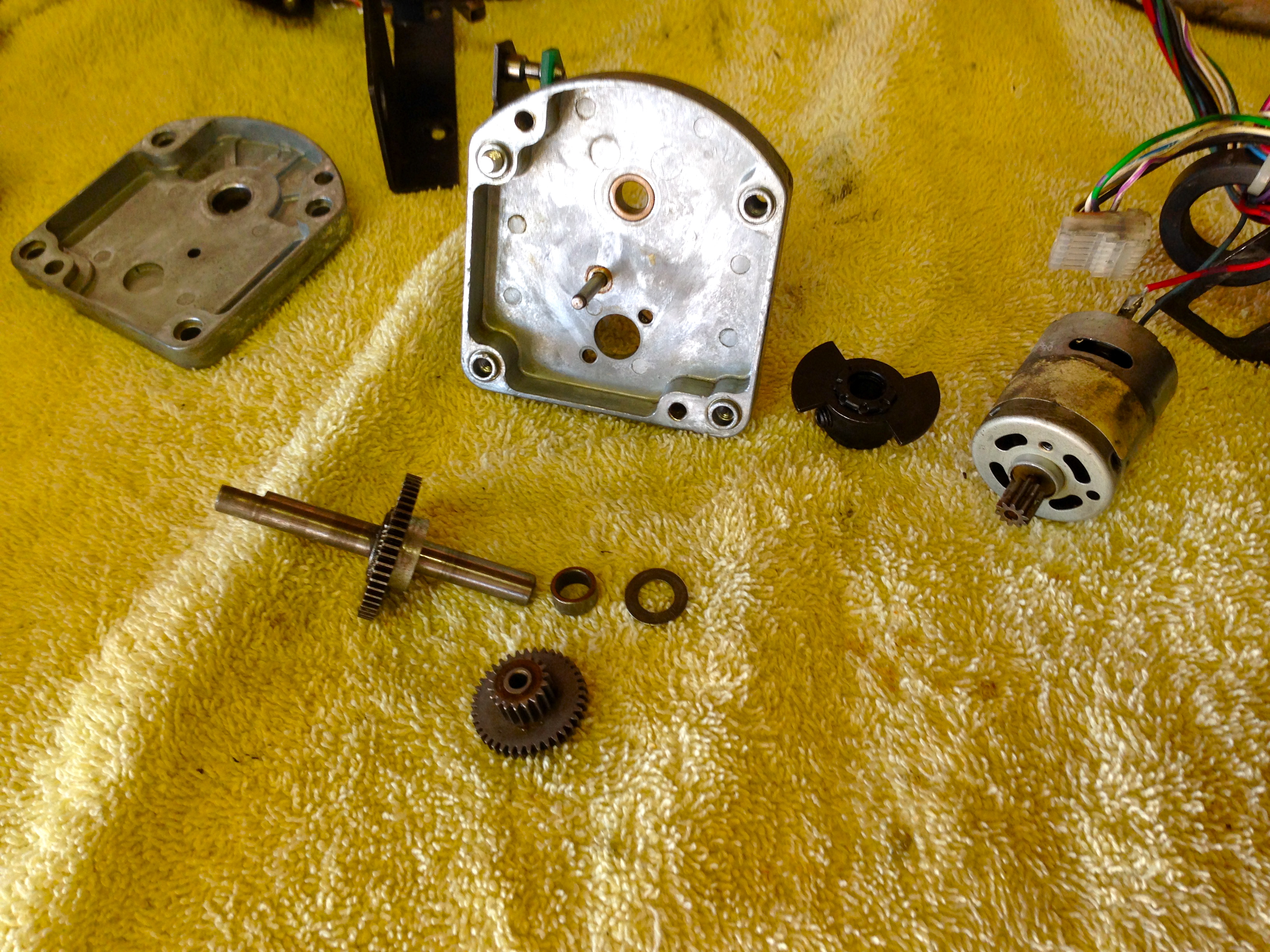
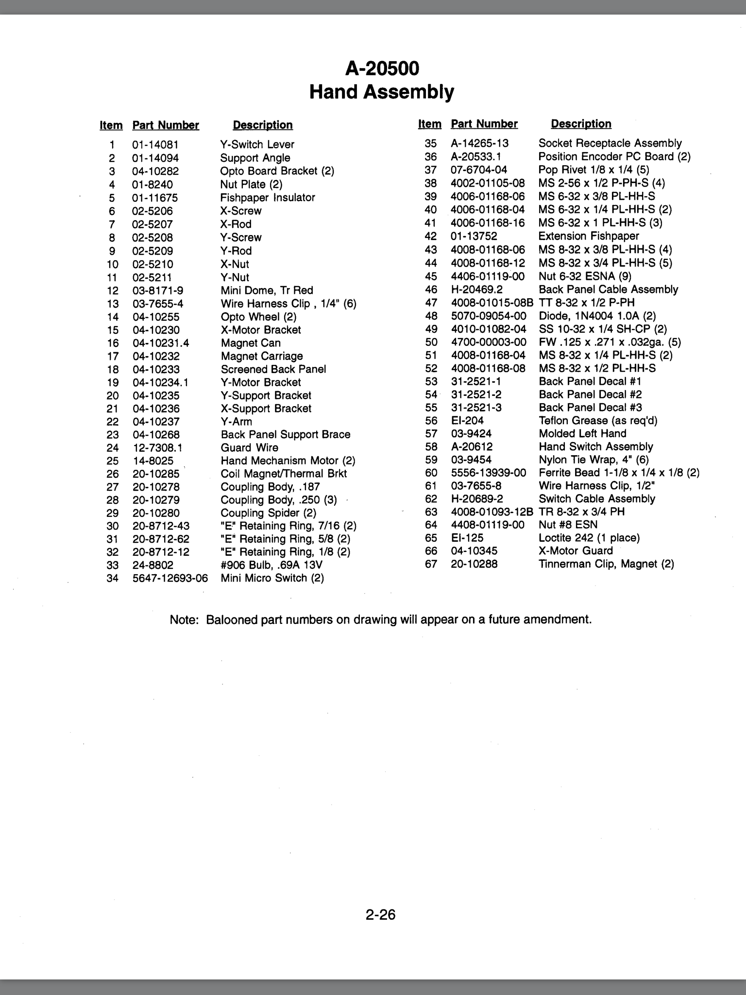
The Y-axis assembly consists of a threaded rod, a special nut that rides on that rod, a smooth rod that carries the top of the carriage, and the carriage itself which holds the electromagnet. At the back is a motor with a gear-reduction box that drives the threaded rod. The X-axis assembly is basically the same, so I won’t cover both.
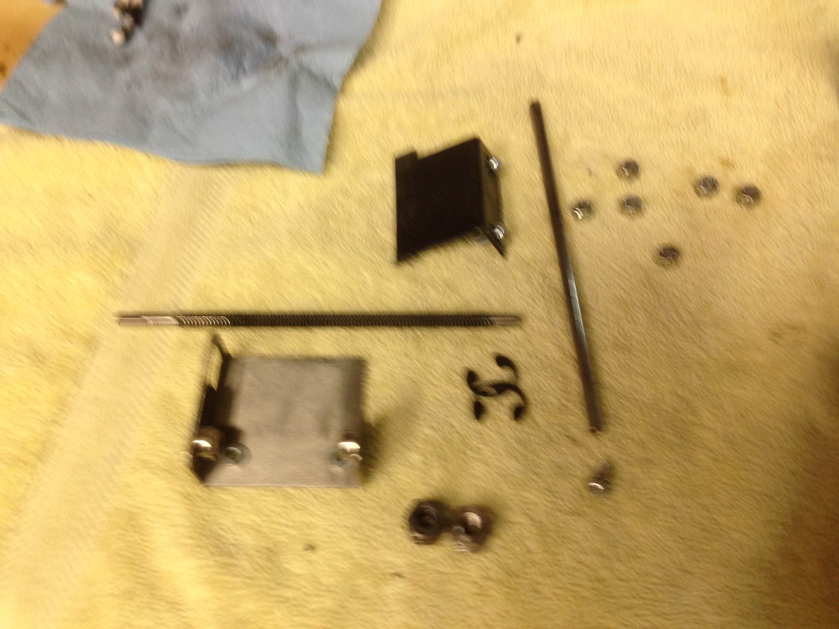
On the axis assemblies, I cleaned all the old oil and grease off both rods (smooth and threaded) using Simple Green. I then reapplied a light coating of grease to the threaded rod. The ends of the threaded rod sit in bronze bushings. Those bushings where cleaned, and a light coat of machine oil applied. The smooth rods have nylon bushings that ride on them, so in theory they need no lubrication. Just in case, I put a very light coat of machine oil on them as well. If nothing else, it will prevent corrosion of the rod.
The grease I’m using is called Super Web Grease. It was originally developed for bicycle chains, but it works great on any mechanism involving gears, chains, threads, or other mated surfaces. It’s similar to white lithium grease, except it stays in place much better, and is immune to moisture. It’s great stuff, and a little goes a long way.
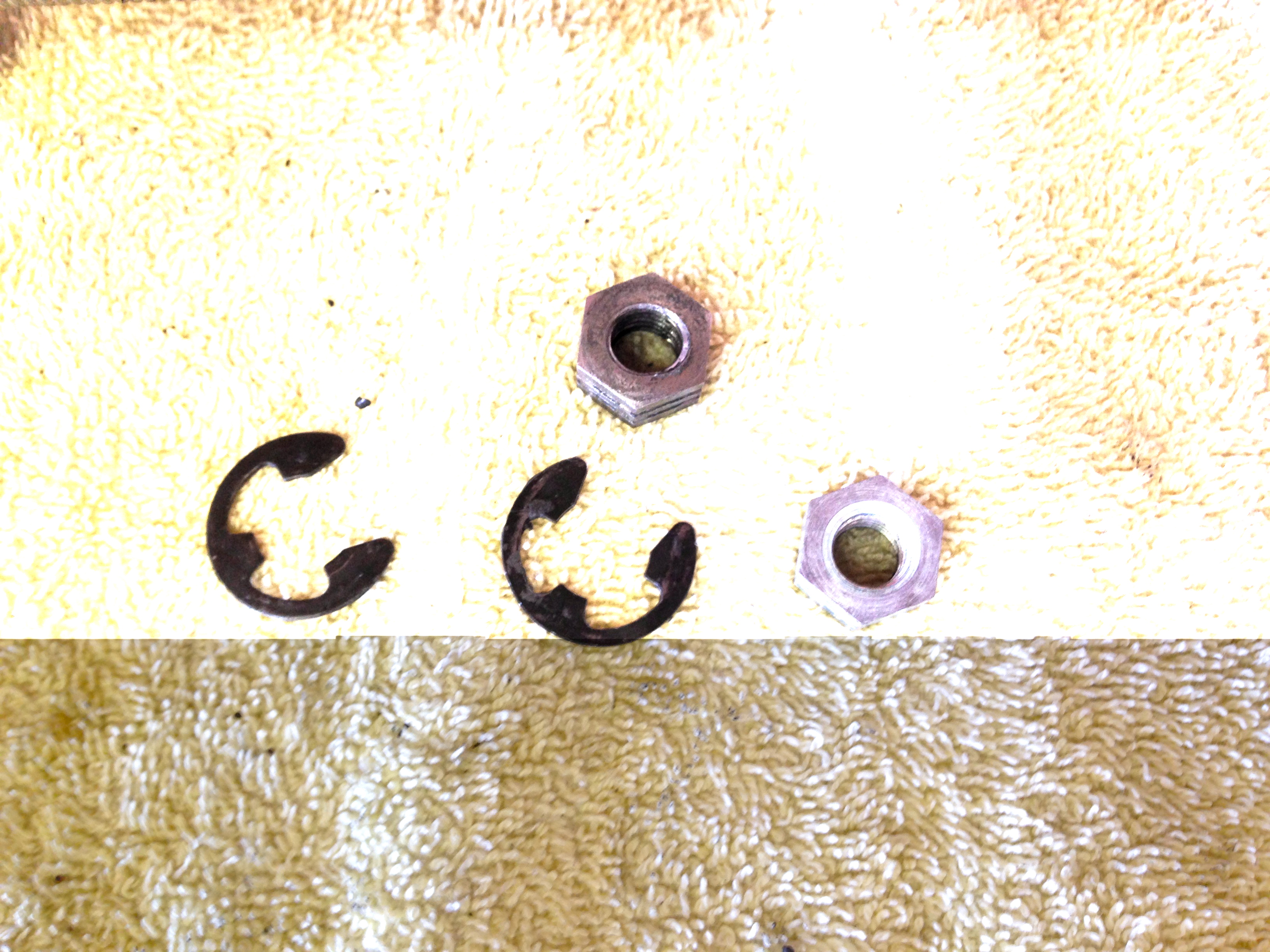
Check for wear on everything as you go, but likely the only part you will need to replace is the X/Y nuts. These carry the mechanism fore and aft as the threaded rod turns. They are intentionally softer metal than the rods so they will wear out first. They are a consumable part, and can in fact be replaced in situ on the machine, if needed. Most mechanical problems with the Johnny hand come down to these nuts being worn out.
Pretty much anything you might need to replace while doing this can be bought from Marco Specialties.
Once the X/Y assemblies are cleaned and regreased, it’s time to tackle the drivetrains. Each threaded rod has a motor and gear box on the end of it. This gear box drives the rod through a rubber spider coupling.
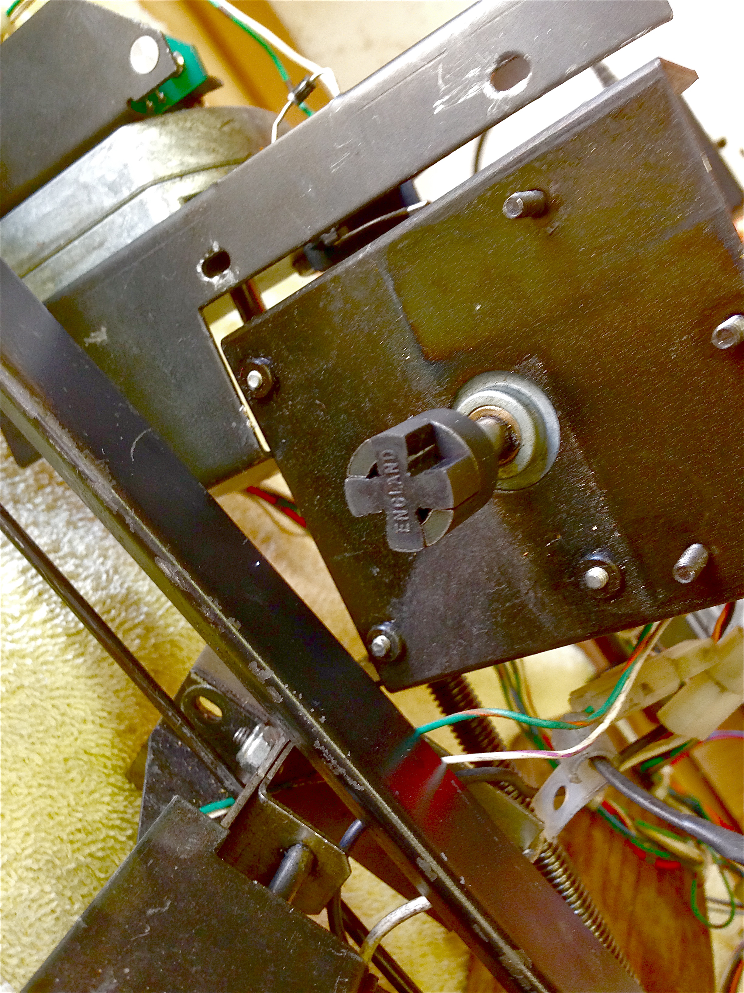
The gearboxes themselves are held together with a couple of screws.
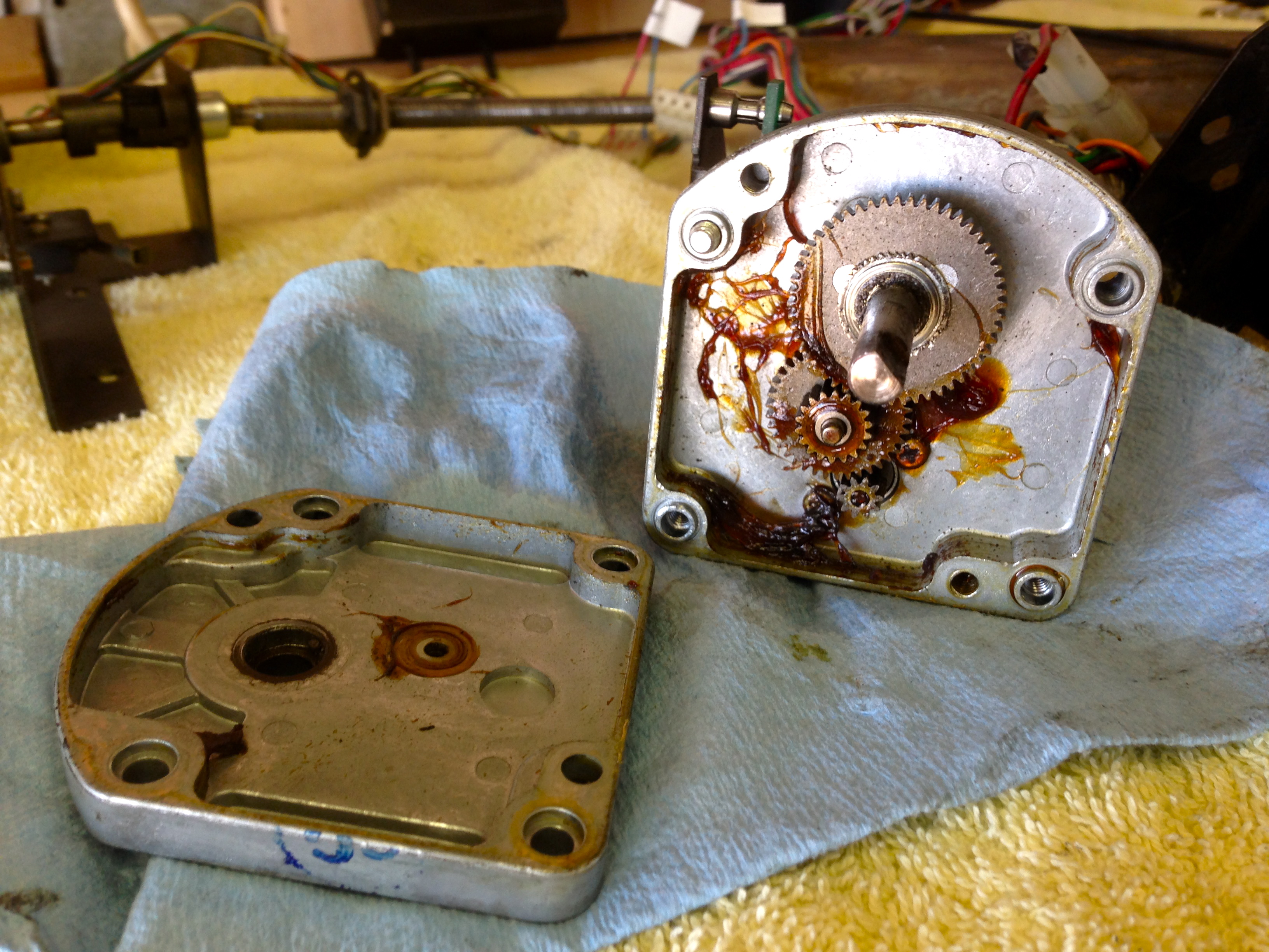
With everything clean, I again applied a light coating of machine oil to the bronze bushings. The gears themselves get Super Web Grease.

I encountered a small problem at this point. In order to fully disassemble the gear train, you need to remove the spider coupling from the output shaft. The set screw in one of my spider couplings was completely stripped out by some hamfisted repairperson in the past. The coupling was secure, but it was going to very difficult to remove. I opted to leave it alone. With the coupler in place, you can still slide the gears out enough to clean and grease behind them, but you can’t do quite as fastidious a job as I did on the other gearbox (shown in the pictures above). Still, you can do what you need to. If I ever need to replace that spider coupling, I have no idea how I’ll remove that tiny stripped set screw. Grr.
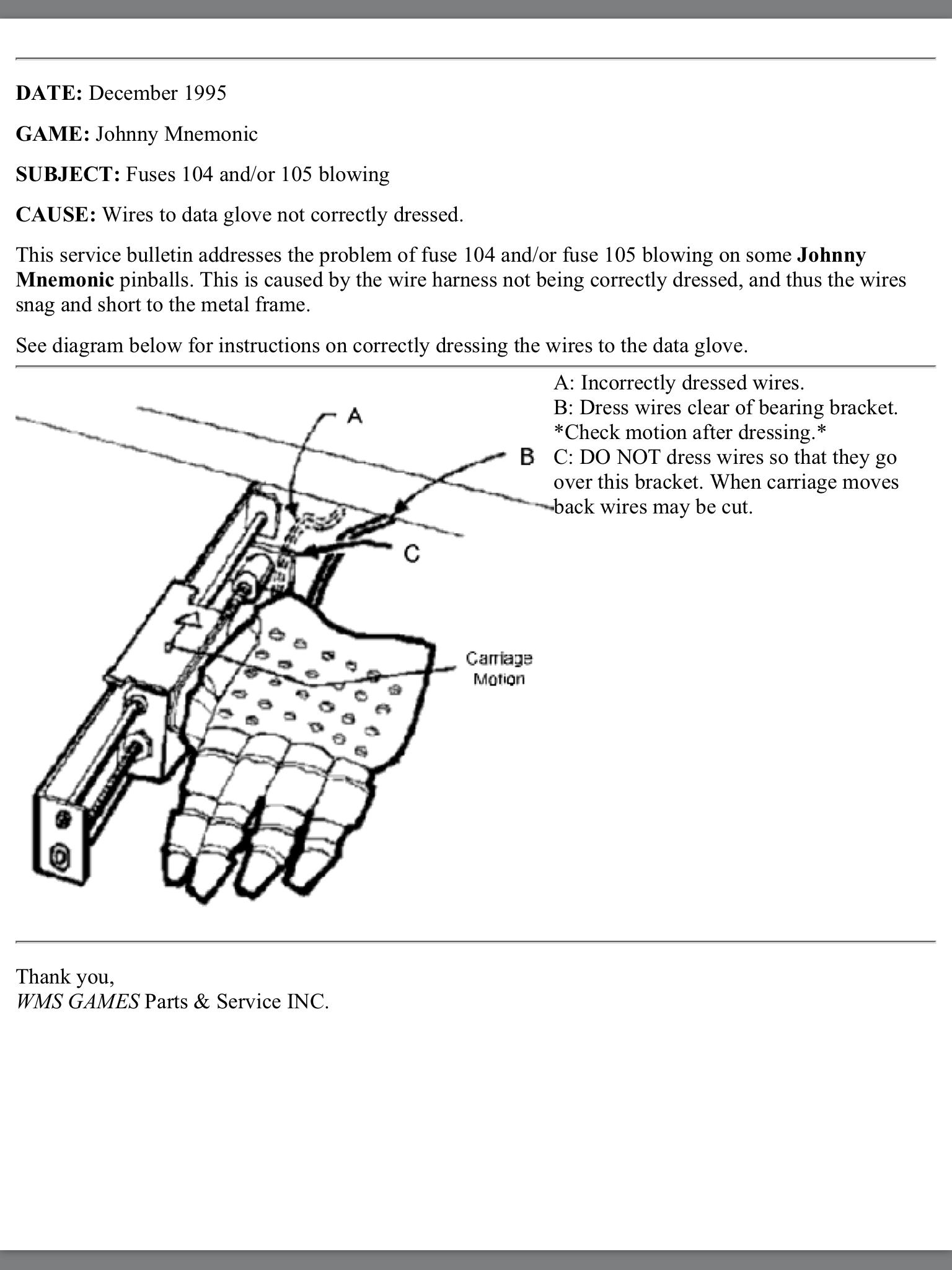
While we’re in here, inspect all the electrical elements as well. Check the wiring for damage. There are a lot of moving assemblies here, and an improperly routed wire could have worn insulation. In particular, check the wires running from the magnet. This is called out in a Williams Service Bulletin:
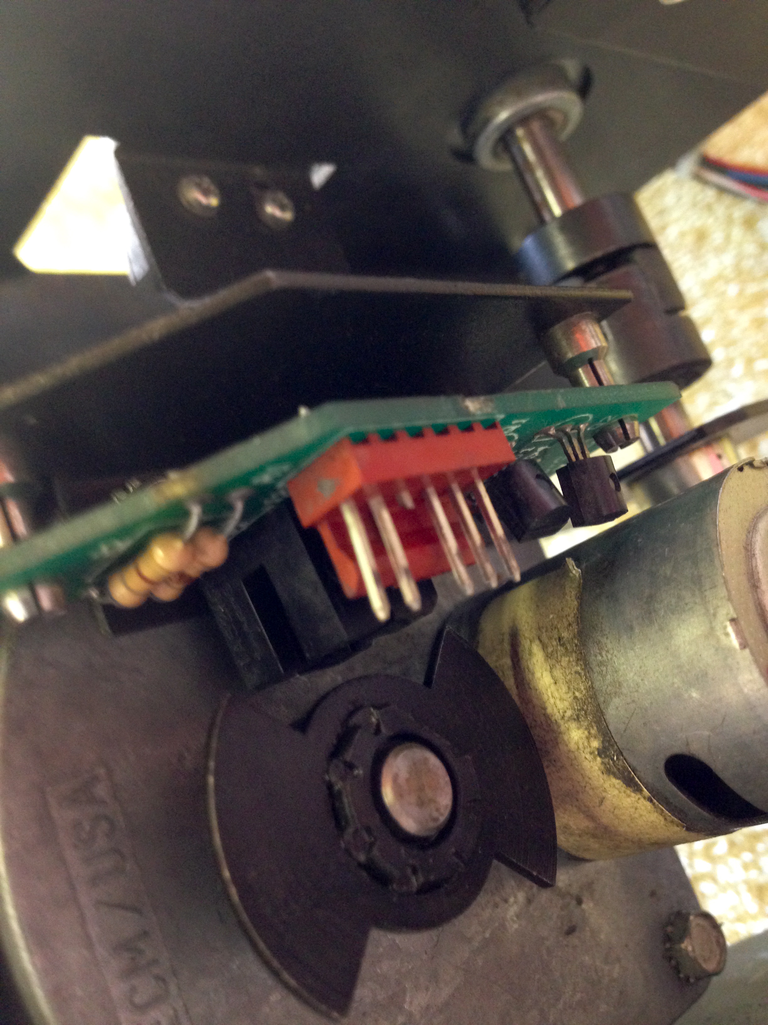
Each machine may have unique issues. In my case, the encoder boards on the back of each motor had clearly been worked on (poorly), and needed some attention. The boards sit on the back of the gear box and optically register an encoder wheel, so the game can measure the progress of the hand on each axis. On my game, someone had replaced the connectors. As I mentioned in a previous article, Williams keyed their connectors by removing a pin. In this case, the repairperson had done so poorly. Before I fall off my high horse and break something, I should note that I did basically the same thing on the power driver board recently. The difference is, I’m totally going to go back and fix that properly. Honestly, for reals, I pinky swear. Ahem. But not right now, ’cause Walking Dead is on. Later. Maybe.
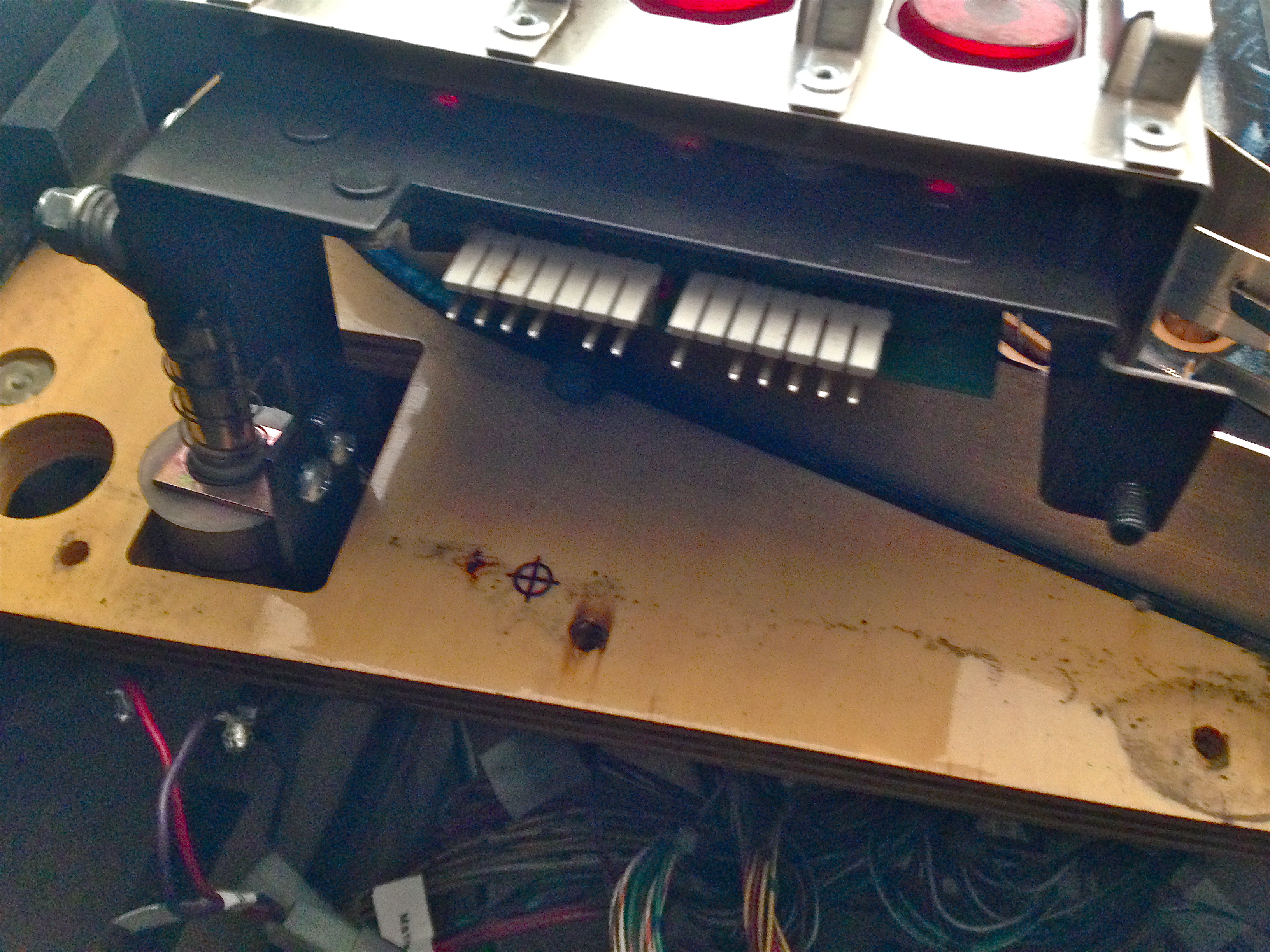
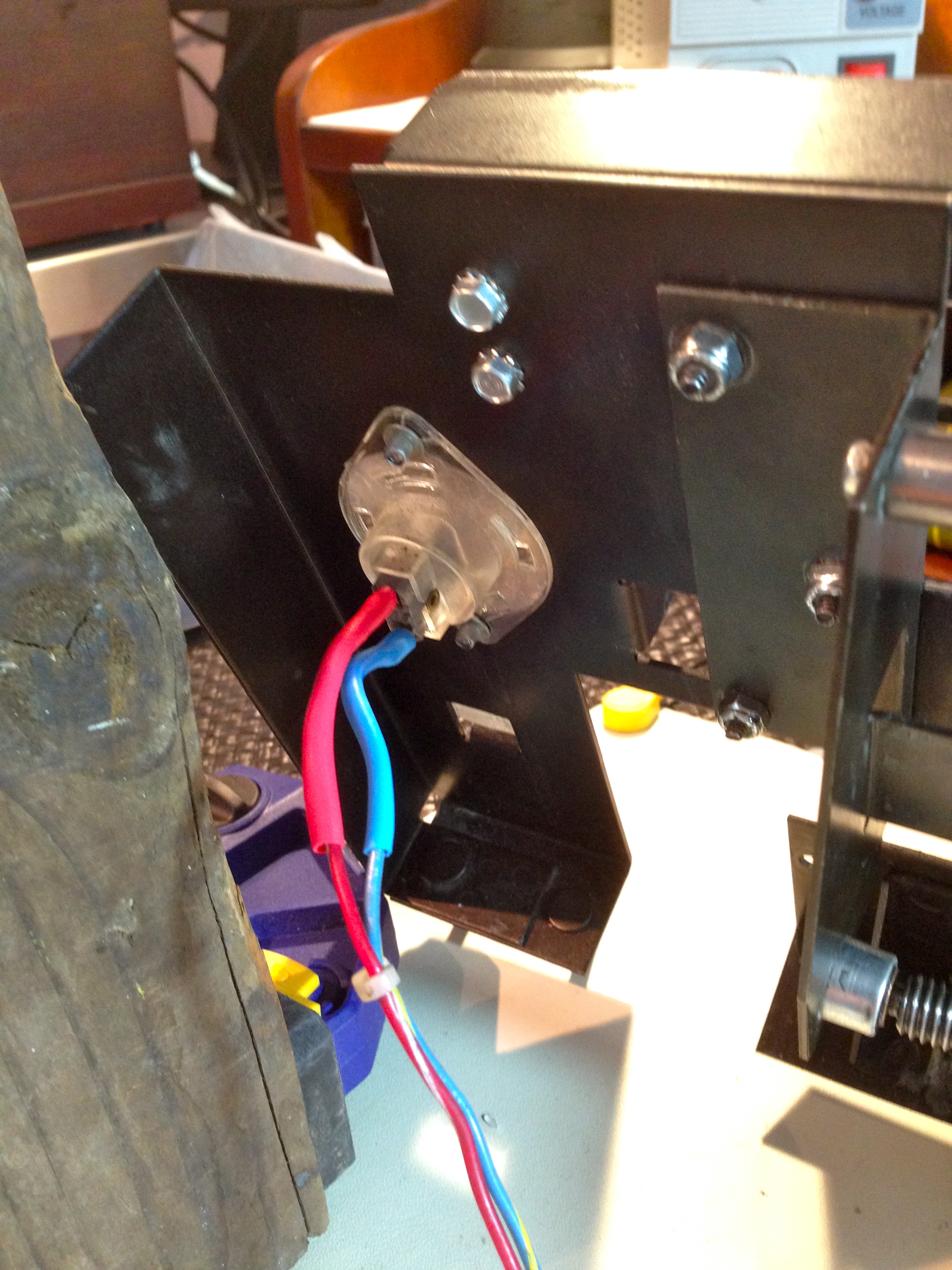
Speaking of service bulletins, there’s another one we can attend to while we’re here. There was a bulletin issued about the connector on the back of the flasher lamp mounted in the backboard. The connector is very close to the harness that runs down the back of the cabinet from the head, and lifting the play field up and down for service can bend the pins, causing a short.
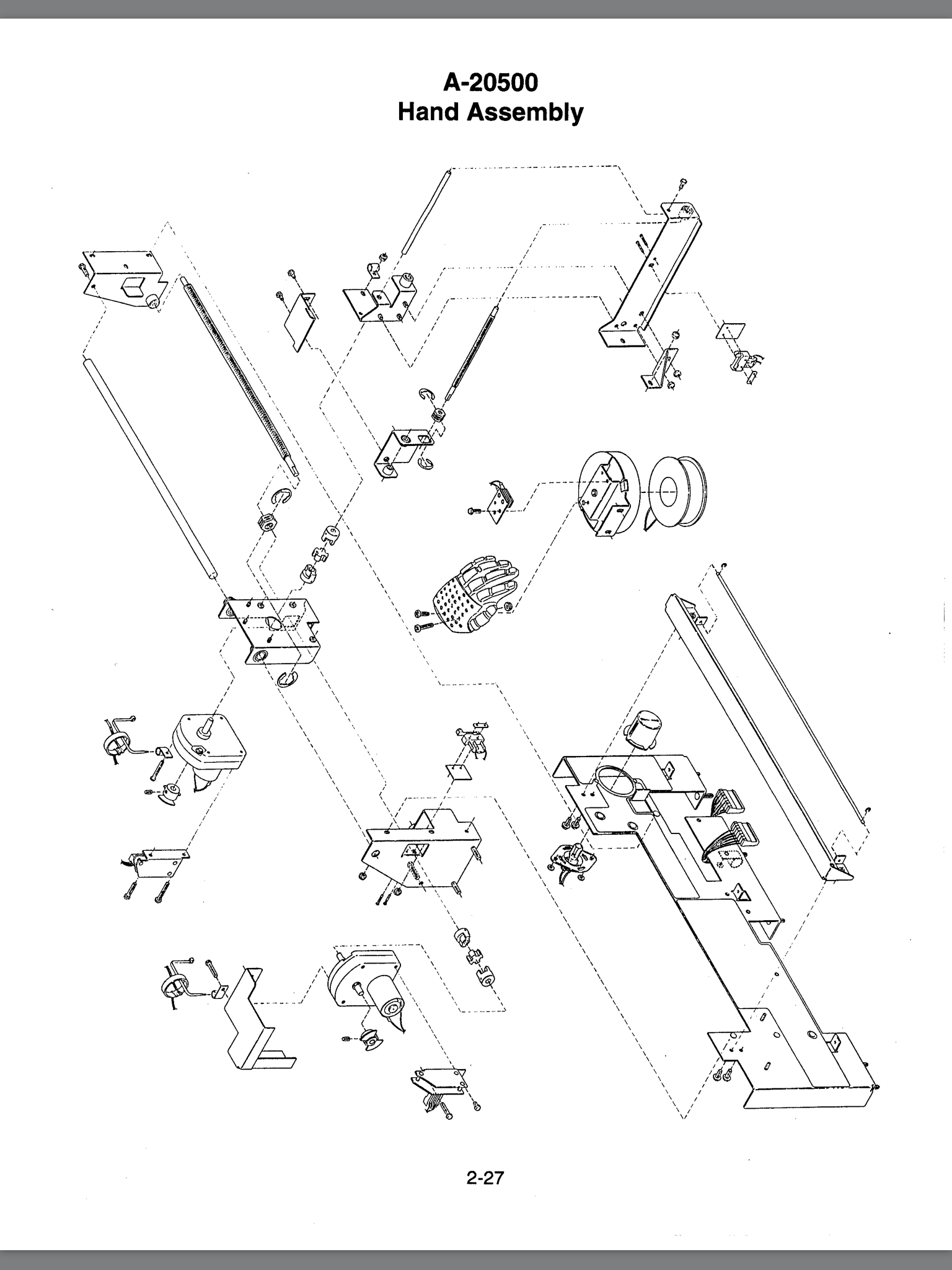
We’re almost done! Reassembling the whole backboard is the reverse of disassembly, and installation is the reverse of removal (as we like to say in the car world). If you forget where something goes, you can refer to the diagram in the manual.
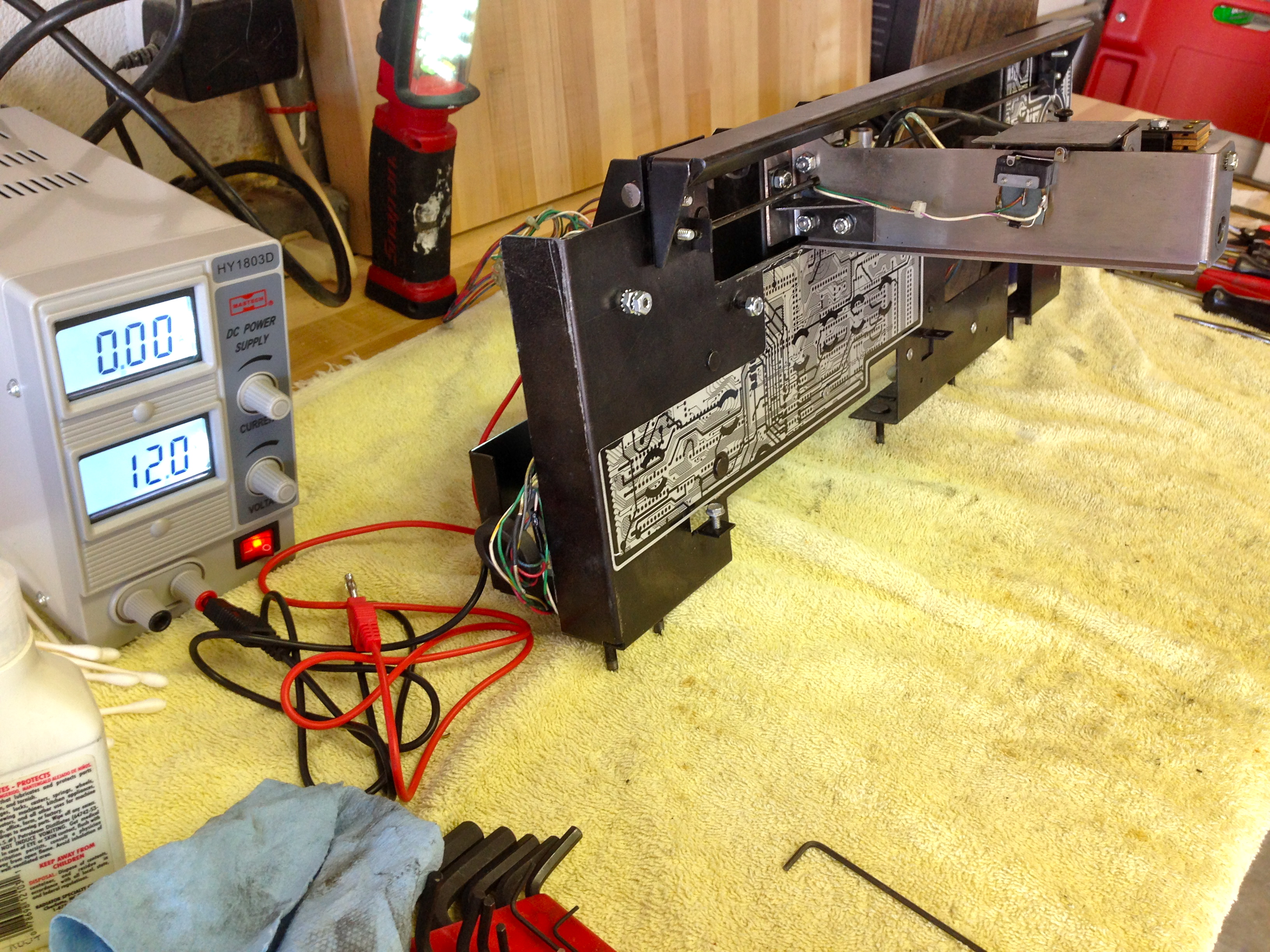
Once the assembly is back together on the bench, it’s a good idea to test it. If something is wrong, better to find out now, rather than inside the machine. I looked up the hand motor control schematics, and it says the motors run on 12VDC:
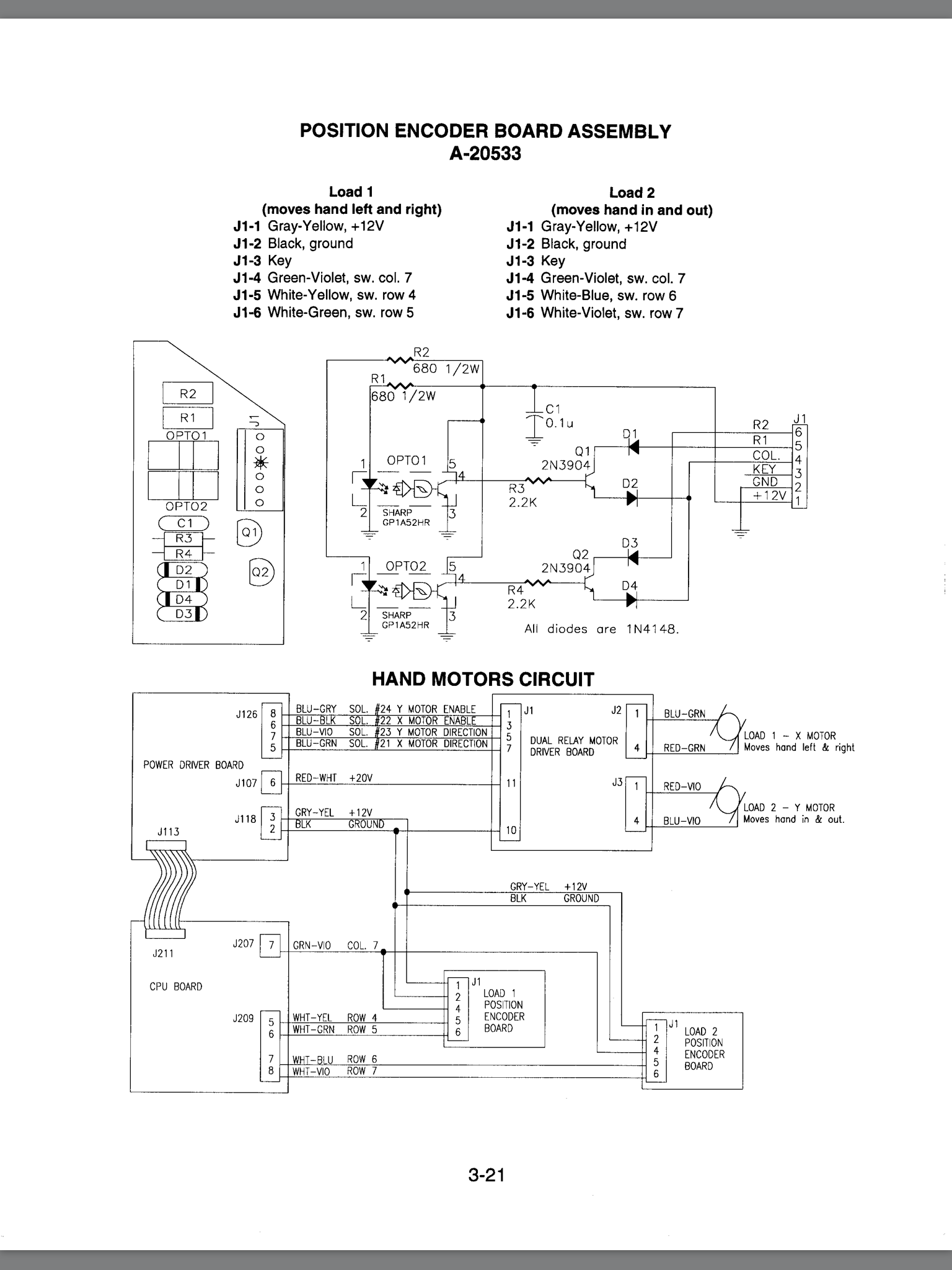
So I set up my bench supply for 12V, disconnected the encoder boards (to eliminate any risk of damage), and powered up each motor manually to check for smooth operation.
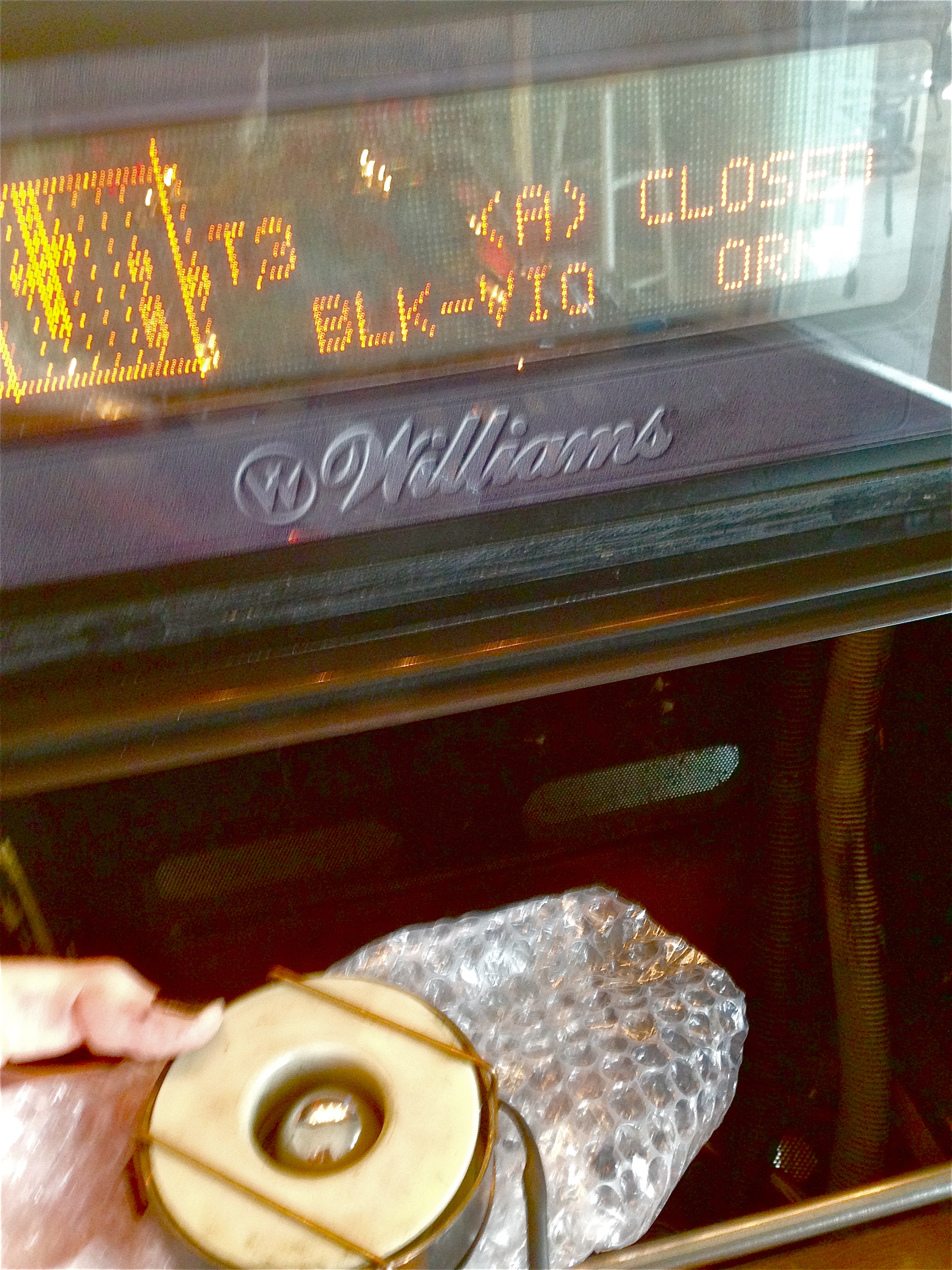
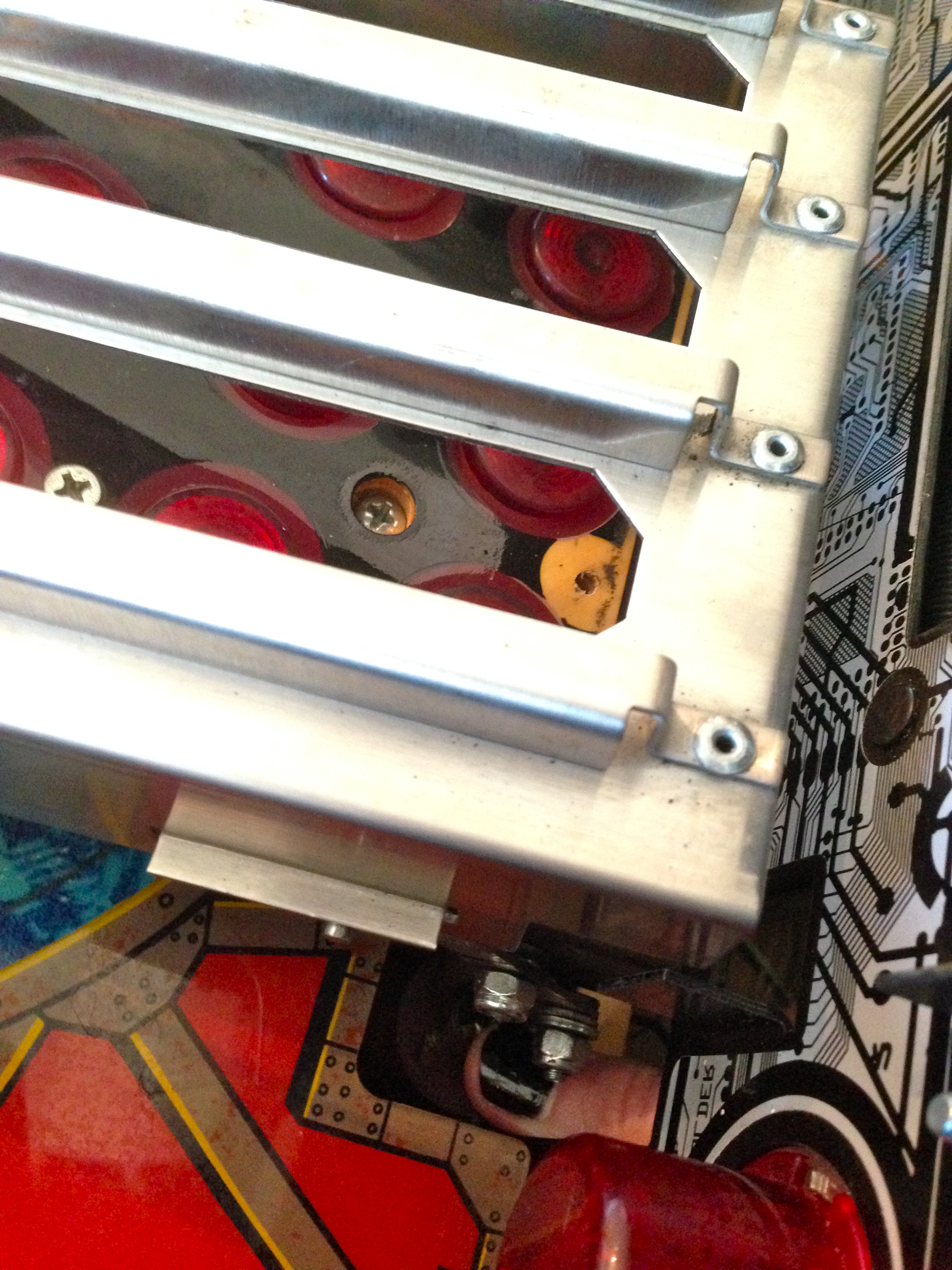
Once the assembly is back in the machine, it’s a good time to check the operation of the Ball In Hand switch. This is a leaf switch that sits inside the electromagnet, and detects when a ball has been caught. The solenoid that kicks the ball up into the hand may not do so perfectly, so the electromagnet needs to be very strong to ensure the ball gets drawn into the center of the hand. Driving the magnet at this high power for long would overheat it, so once the ball is caught, the computer duty-cycles it. Less power is needed to hold the ball once it is caught and under control. The ball-in-hand switch is what triggers the lower duty-cycle of the magnet.
This is another notorious failure point on this machine, and it’s the subject of yet another Williams Service Bulletin. A lot of people remove this switch entirely, based on a rumor that a code update for the machine eliminated the need for this switch. I’m unconvinced of that, particularly in the face of Williams SB 85, which details the importance of this switch and how to calibrate it.
The procedure for calibrating it is to hook up the wiring for the magnet, but disconnect it physically from the hand carriage. You then power up the machine, hold the magnet upside down in your hand, and place a pinball in it.
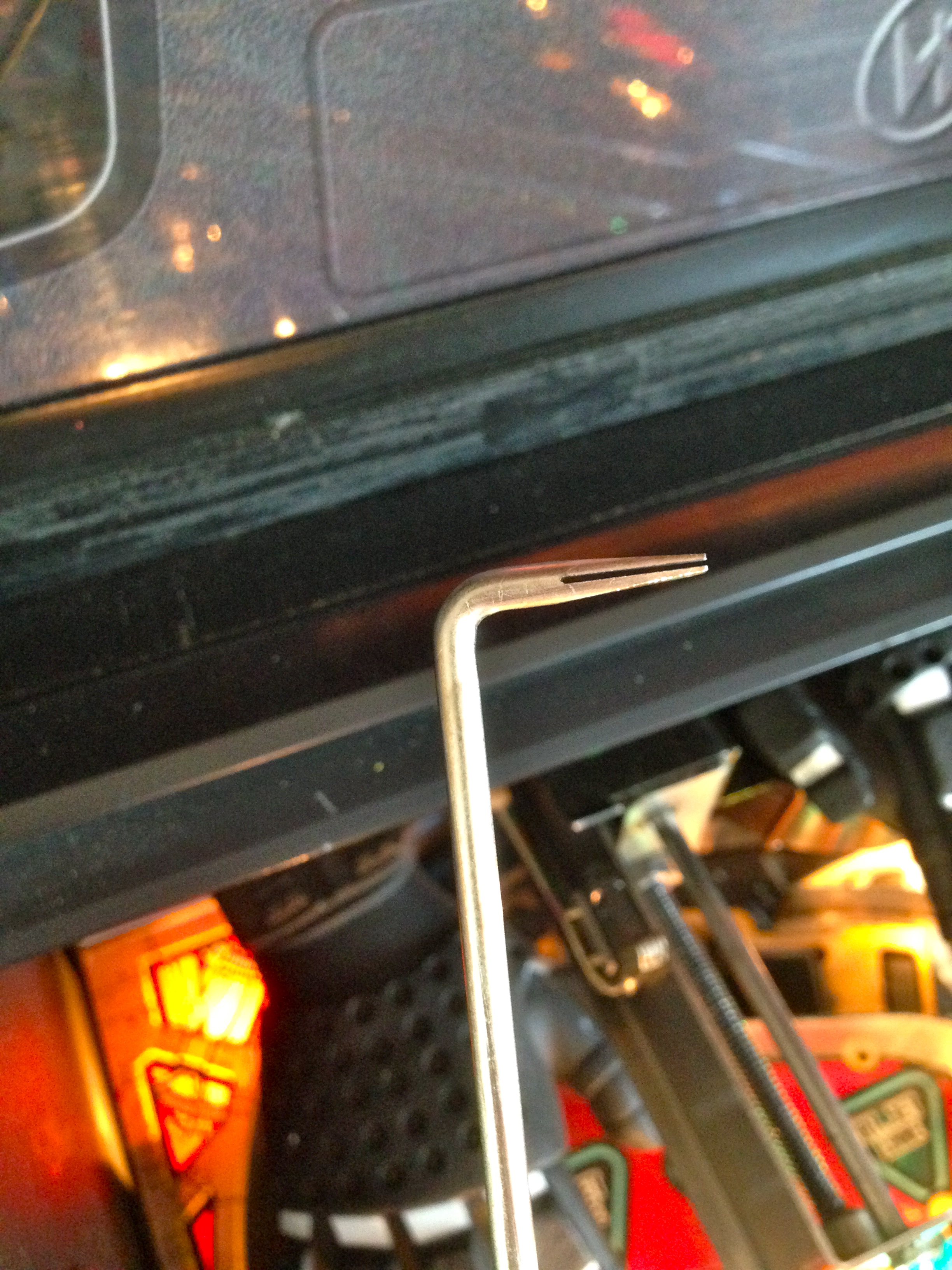
If your Ball In Hand switch needs adjustment, as mine did, you need a leaf switch adjuster tool. Resist the urge to bend it by hand. You’ll introduce weird curvatures into the leaves that you will never be able to remove, and the switch will gradually perform worse and worse.
Once everything was reassembled, I ran through the solenoid tests to see if everything was okay wiring-wise. The cybermatrix was no longer lifting to unload balls. Rut Roh, Shaggy!
That’s all she wrote! So after all that, did I actually fix it?
Like a boss. Enough shop talk. Let’s play some goddam pinball.
I know in competition they disable the hand completely, it breaks the scoring really badly. JM is such a cool machine. The Matrix conversions of JM look really cool.
Always nice to see a pin restored to full working order!
Yah, I’ve also read that the Spinner Millions mode on this machine is basically like Double Jeopardy- it renders all previous scoring and gameplay pointless. I’m not sure if it’s possible to disable that in the settings (there are SO many settings!), but it could be a problem for tournament play. For casual play, fortunately, none of that matters too much. What’s great about this game is the ability to set your own goals- go for score, go for Powerdown, go for Gigabytes, there’s a number of ways to play it.
“and basic hand tools are all you need.”
I see what you did there 🙂
ROFL- I wish I could say that one was intentional. But I’ll take credit for it anyway. 😉