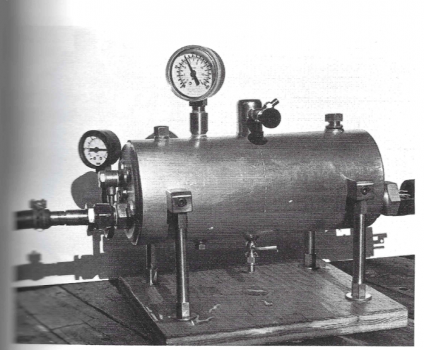
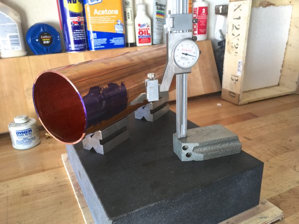
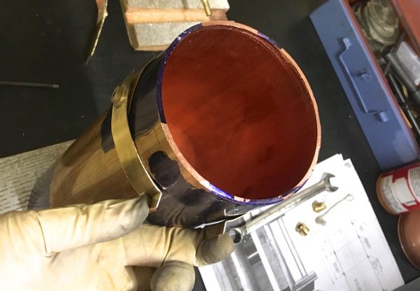
Supporting a big cylinder turns out to be pretty hard.
With the boiler shell basically ready to work on, it was time to finally get down to making some parts. The legs seemed like a good place to start, because they are pretty straightforward parts and make for a good way to ease into this hefty project. Little did I know the legs would be such an odyssey! Design iterations and failures abound in this seemingly simple job, so buckle up and witness me.
The purpose of the legs is twofold. First, the boiler needs to be off the ground so that the base plate doesn’t get burned (if wood) or rob us of precious heat (if metal). An air gap underneath it acts as an insulator. Second, and more importantly, there needs to be room for fittings on the bottom. Different boiler designs will involve different fittings, but it’s a safe bet there will always be at least a drain valve. Often there is also a blowdown valve (which may be the same as the drain valve) and in our case there’s also part of the sight-glass system for monitoring the water level. In a real stationary boiler, it would be typical for it to be sitting in a built-up cradle made of bricks or cast iron. We’re going make legs because it looks nice and is easy to do (for certain values of “easy”).
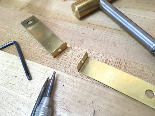
The design that D.E. Johnson came up with for these legs looks quite attractive and is straightforward to make, so I started out copying what he did verbatim. His design consists of four legs, each attached by a right-angle bracket that attaches with a ferrule through the side of the boiler shell.
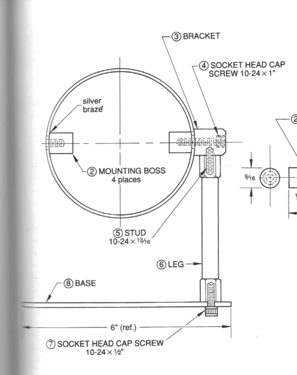
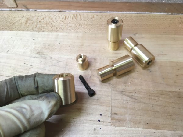
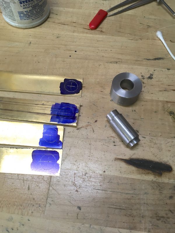
I deviated a bit from that design straight away, because I didn’t care for the square piece that supports the legs. It felt awkward to me amongst all the round details, so I decided to make all these parts round.
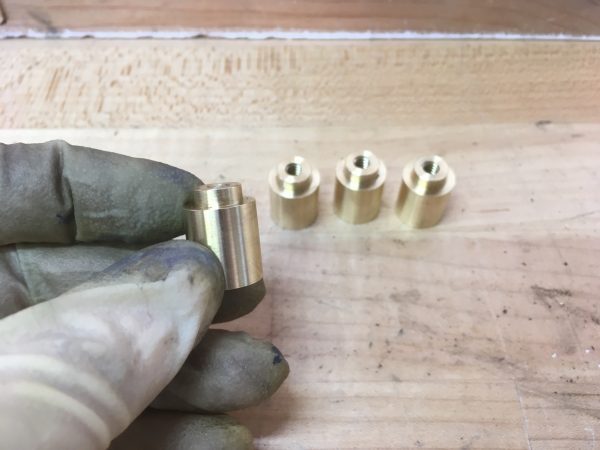
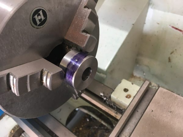
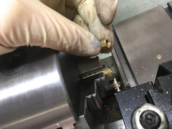
Next, we need to make the bosses that attach through the shell to those ferrules, and support the legs. As I said earlier, I decided to make them round.
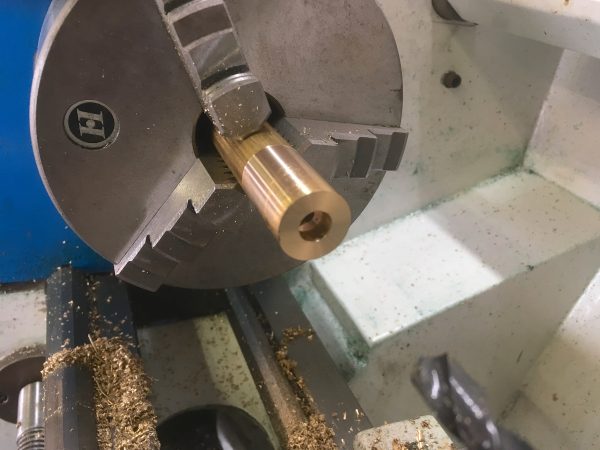
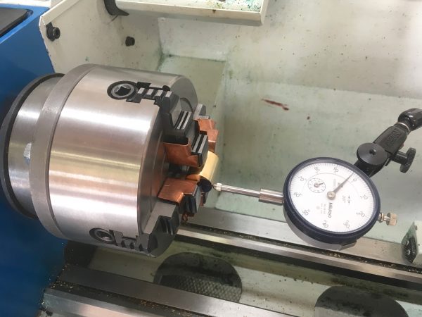
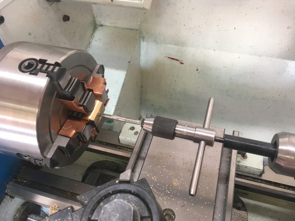
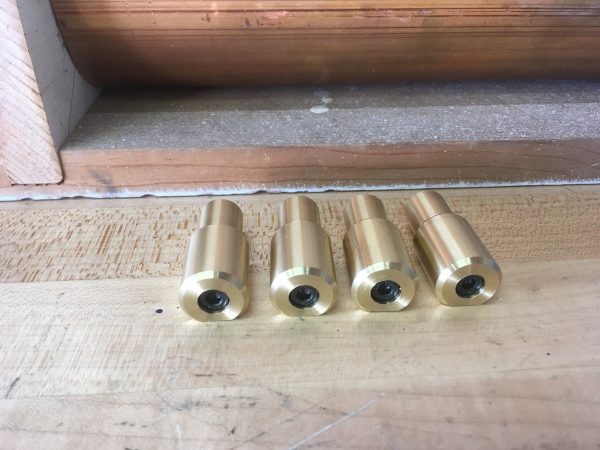
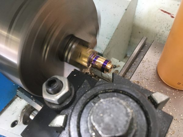
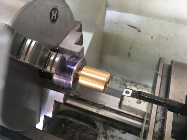
Next up are the legs themselves. These are made from hex stock, mainly for appearance. Hex stock is a lot of fun to work with, and we’ll be doing a lot more of it on this project. You can get very attractive and functional parts by turning down sections of the hex to varying degrees of roundness. You also get attractive effects with chamfering and filleting tools on hexagonal profiles. The one trick with hex stock is that it is difficult to get concentricity with it. If you use the three-jaw chuck, it’s easy to hold, but you’re at the mercy of how true the stock is. Since you have to preserve part of the original surface (otherwise why would you be using hex stock), you lose the ability to “cut below the run-out”. You can set up hex stock in a four-jaw chuck, but dialing it in is really tricky, and two of the jaws are holding on corners, which is awkward and not very rigid. The ideal chuck is an independent six-jaw, but those are hardly common in weekend-warrior machine shops.
The bottom line is, don’t use hex stock for something that needs good concentricity. This is rarely a problem in any case, because if you’re using it, you’re probably making bolts, plumbing fittings, or decorative elements. None of those need crazy high concentricity, typically.
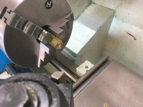
Note that parting off hex stock can be slightly alarming. It’s a very interrupted cut, and parting blades do not appreciate being treated that way. Very low RPM and gentle feed are the rule until you get deep enough to have a continuous cut. It will sound like a little baby power hammer until then.
I was pretty pleased with myself at this point, but a dark cloud was coming. Over the course of many showers and commutes, I was thinking about this leg system and decided it had a critical flaw that I really didn’t like- it requires cutting gratuitous holes in the boiler shell. This is a pressure vessel, and every braze joint that we subject it to is a potential point of failure. I’m also not a particularly good brazer-person. So why would I ask for trouble by using a leg system that demands four extra pointless holes to be made?
I couldn’t bring myself to do it. Instead, I decided to head off the ranch and do something different. All the ideas I had revolved around some sort of clamping-band system that would wrap the boiler and hold it like you might support a pipe in a ceiling. My idea was to have a continuous band over the top, to which one pair of legs attach. The bottom clamp would be two pieces, attached to the legs, but with a gap at the bottom. This gap would be bridged by a bolt that can be tightened to get the clamping action. The bottom clamp would squeeze the boiler upwards into the top clamp, securing it firmly.
I decided to reuse the ferrules that are supposed to go through the boiler, and instead braze them to the bands that wrap around the boiler. This way, the bands would sit flush all the way around, which would be quite attractive, and the legs still screw in as before.
To make the bands themselves, I fished some 24ga brass sheet off the junk pile. Now, I knew I had a challenge ahead. Sheetmetal work is one of those things where, if you have the right tools, it’s easy and pleasant. If you don’t have the right tools, it’s hell and the result always looks kinda like garbage. I was in the latter camp, but determined to minimize the garbage part. I don’t have a press brake, a shear, seaming pliers, a nibbler, or any of the other things one should use for sheetmetal tasks. I wasn’t about to tool up a whole sheetmetal shop in my laundry room for this one little job though, so let’s see about making due.

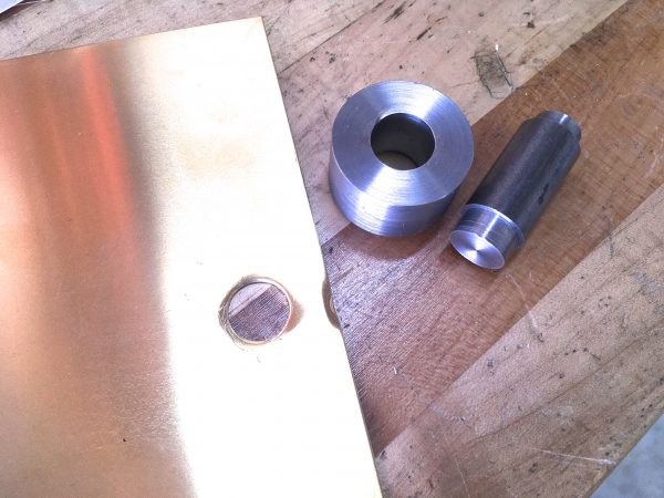
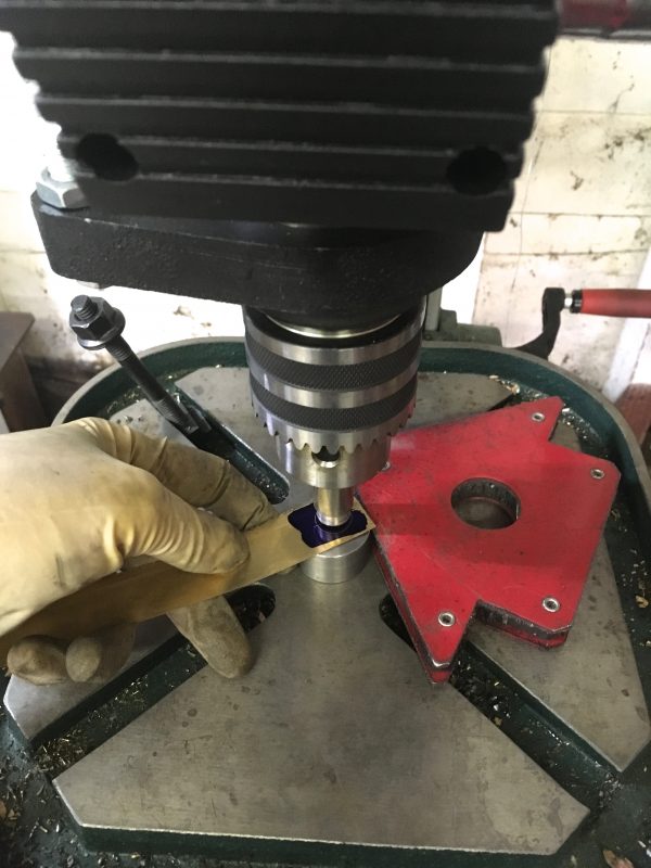
I know from previous agony that drilling sheetmetal cleanly is a pain in the patouie. The drill deforms the piece, the piece grabs the bit and twists itself up into knots, cats and dogs live together- it’s terrible. Instead, I thought I’d try my hand at making a punch. I’ve never made one before, but the tolerances can be looked up and a punch is ultimately just a round thing with a slightly larger round thing for a die. Lathes are great at making round things, and I have a lathe. Onward!
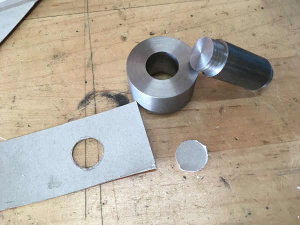
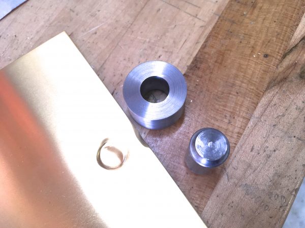
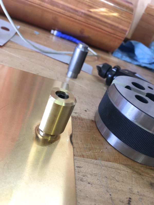
Ideally, a punch like this would be made with tool steel, not mild steel like I’ve done here. However, this will only be used on brass, and only needs to survive for eight holes, so I’m not concerned. Okay, enough theorizing. It’s the moment of truth- does it work in actual brass?
The next challenge was getting nice one-inch-wide strips cut from my brass stock. Again, the correct tool for this (a shear) makes this a painless task (as long as you keep your fingers out of said shear) and delivers perfect results. I needed another way.
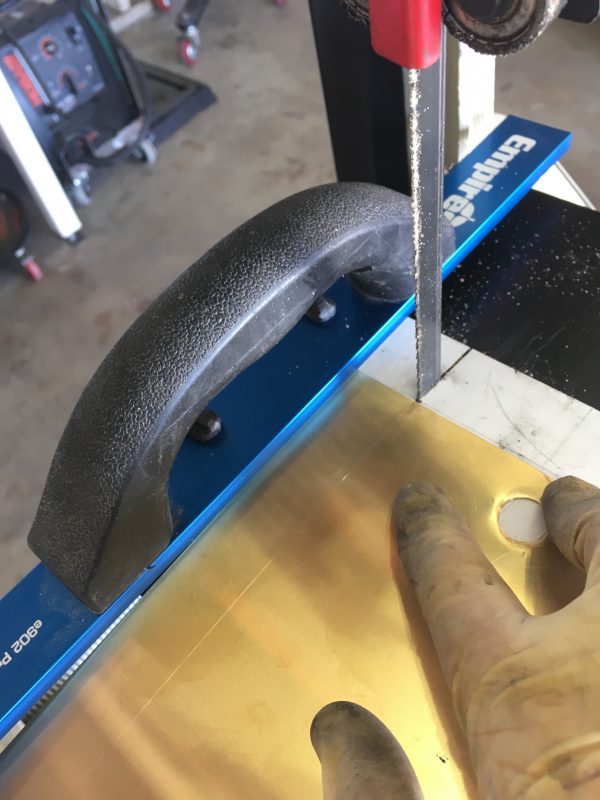
The rule of thumb on bandsaw blades is that three teeth should be inside the material during the cut. For 24ga material, that means you need a very fine-toothed blade. This idea was a no-go.
I also tried tin snips, out of desperation, even though I knew it would make a deformed, roughly-cut mess (because tin snips always do). I didn’t bother photographing that train wreck.
The one thing I found that worked okay was a jigsaw with a very fine blade. The material has to be well supported and clamped close to the cut on both sides to keep from vibrating and deforming, but the resulting cut is actually fairly decent.
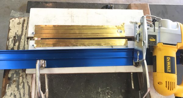
I made four strips with the jigsaw method and set about making some holes.
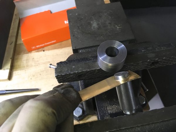
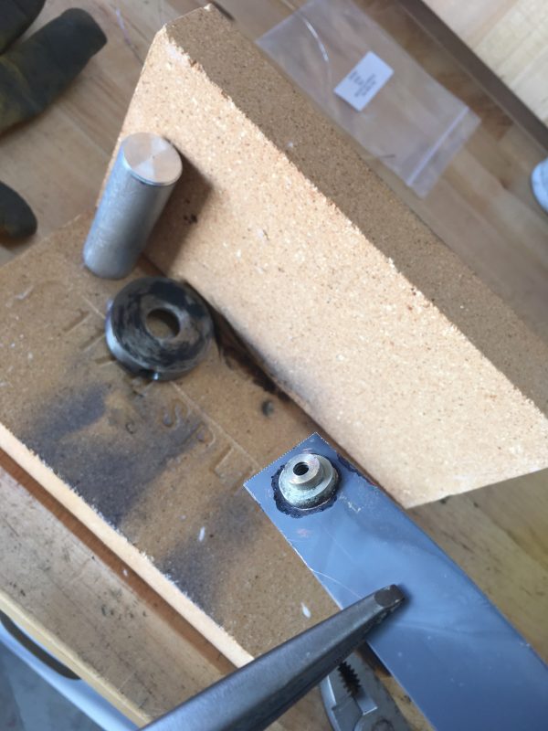
With the clamps cut to length and punched, it was time to braze in the bosses. To the fire bricks!
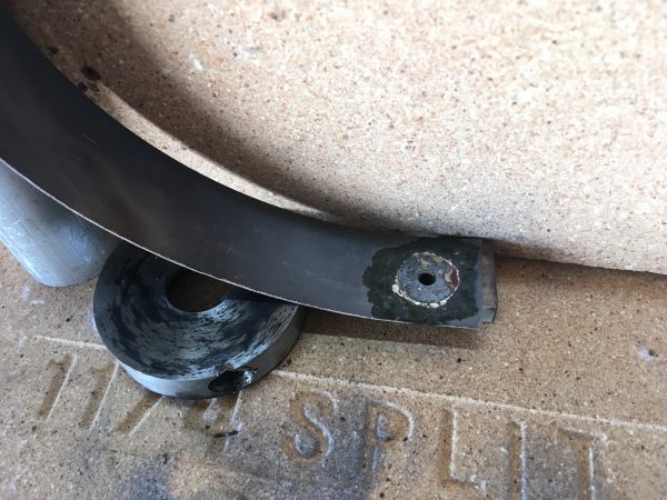
This is the point where things started to go really wrong yet again.
To make matters worse, while fitting the bottom clamp, all my braze joints to the ferrules on the top clamp started cracking and failing. 24ga sheet just wasn’t enough cross-sectional area for a secure braze, and the joints gave up the ghost under very little provocation. Recall also that I wasn’t happy with the pieces made thus far- misaligned holes, saw cut marks, etc. Everything was just sub-par overall.
I had used up all my brass sheet stock in all these various failed attempts at cutting, punching, brazing, etc. Each step in the process failed multiple times, and that’s usually a sign that the whole enterprise is on the wrong strategy. It was time for a stop-and-think, as my mom used to say.
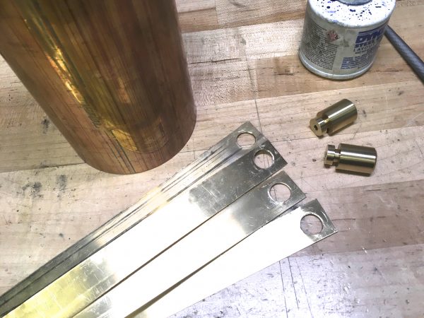
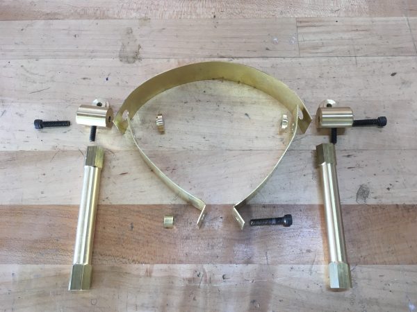
I decided to start over with a different approach. I would not rely on brazing- the ferrules would clamp through the bands with screws. That would mean the clamps would have a sort of oblate-sphereoid shape to them, but the system would be secure, reliable, and easy to make. Second, I gave up on cutting nice brass strips, and simply ordered 1″ wide material. It felt like cheating, but the result is much nicer. Finally, I gave up on my homemade punch, since getting repeatable well-aligned holes with it was proving impossible.
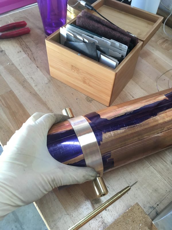
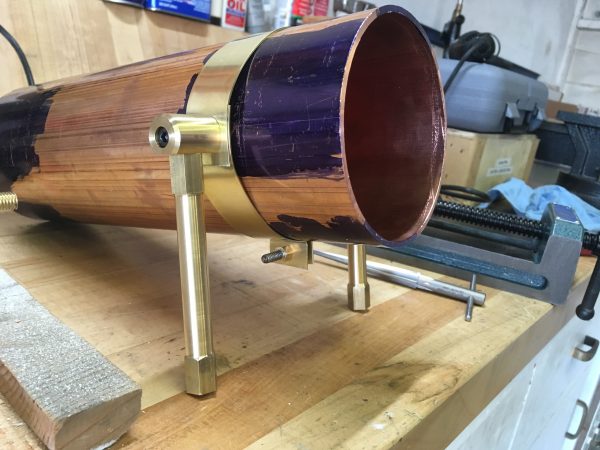
With all the band clamp pieces remade (dimensions adjusted for my new bolt-through ferrule strategy), it was time for a test fit. “This one time, at band clamp…”
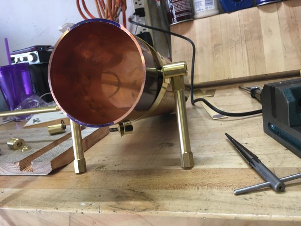
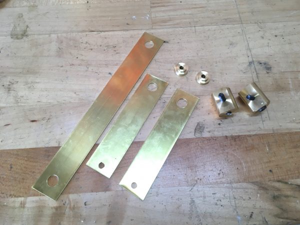
The final step was to attach the legs to a brass plate. This plate serves to stiffen the whole leg system, and also protects the eventual wooden base under the boiler plant from the heat.
I could not be more pleased with how this leg system turned out. While it was a painful process, the end result was all the more satisfying for it.
Now we can get started making plumbing fittings and all the other bits and bobs that will make this empty shell into an actual boiler. Stay tuned!
Instead of bosses, could you have used countersunk bolts stuck through the brass plate into the leg holders from the inside? Countersink the leg holders, with extra space for the brass plate, then just let the brass plate bend into the holder by the force of the bolt. That would have given you a flat brass band all around the boiler.
I think you’ll need to draw me a diagram of what you have in mind there?
Here’s a (potato) drawing of it: https://imgur.com/a/8S9w3
The leg holder is countersunk, the bolt goes through a hole in the brass strip, and as you righten the bolt the strip just around the bolt hole bends and is held between bolt and leg holder. The strip ends up flush with the boiler itself.
I’m interested in this idea! Unfortunately the image link above didn’t work for me.
Would the bolt go through the boiler shell in your setup? Or be threaded just into the clamp?
Do you have a suggestion for a place I can upload the image so you can see it?
The bolt goes through only the brass strip, from the inside. Then it goes into the leg holder. The bolt head is not square, but conical. The bolt holder is countersunk to the same shape, with a bit of extra space.
When you tighten the bolt into the leg holder, the malleable brass material around the hole in the brass strip will bend into the holder. When it’s tightened, the brass strip will be held tightly between the bolt and the leg holder.
If you were to unscrew the bolt, the brass strip would retain the shape of a cone sticking out from the surface, but truncated with the hole for the bolt.
Does that make it clearer?
Oh, I see what you mean now!
The brass strip is very thin, is the thing. I suspect there wouldn’t be enough material for what you’re describing. It would be worth a try though!
Oh yeah, the new legs look niice. Sometimes it takes one rough prototype to help you understand how things really work. I’ve had my fair share of failures that turn into better ideas once you get to hold them in your hands.
Long time lurker, first time caller.
One thing to keep in mind when designing these legs (supports) is thermal expansion. While the pipe here is very short, there will still be some thermal expansion as everything heats up (depending on steam pressure, I would guess a little under 1/32″). The issue isn’t with the actual thermal expansion, per se, but the force that can generate on fixed supports; even a fairly small expansion can put a decent amount of axial load on the supports.
Typically we use roller supports for piping that will experience any decent amount of thermal expansion so that the pipe isn’t too rigidly constrained. I can’t tell from the pictures if the band clamps you made are so tight as to be an anchor or have some slop to allow for some movement without binding.
I spent a lot of time thinking about the thermal properties of this system. The coefficient of expansion of 360 brass is slightly higher than copper, so I think the band clamp should expand with, or slightly faster than, the boiler.
Making some nice progress. Nice that you shared the whole process you went through. The troubleshooting and problem solving thought process is something I always find interesting and it’s a good reminder to not settle for something you’re not happy with.
Thanks! Sharing the mis-steps and pivots is important to me here. I think the usual format of a highlight-reel-of-success that most people use is less informative and interesting.
Quinn,
Nice job sharing the toils and tribulations. But I wonder why you didn’t got with just one band around the pipe, with two holes for the supports, and then the tension part on the bottom? Was your sheet stock not long enough?
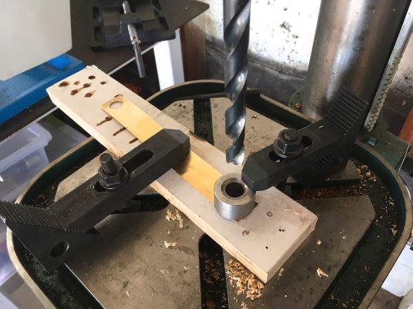
And I liked the change from punch to drill guide as well, turning the weakness of the drill press into a strength.
And I feel terrible that I just recently tossed out a small arbor press that was cluttering my basement for 15+ years. I just never found a need for it and I could I have just given it to someone who would have put it to use. Very much like this Harbor Freight one:
https://www.google.com/url?sa=i&rct=j&q=&esrc=s&source=images&cd=&cad=rja&uact=8&ved=2ahUKEwifrpn2mL_aAhWnwlQKHY2qCREQjRx6BAgAEAU&url=https%3A%2F%2Fwww.harborfreight.com%2F1-ton-arbor-press-3552.html&psig=AOvVaw1JrGhFMAlRZ5j3jzSM9JJ_&ust=1523981836632618
Very astute question on the single band, and you are exactly right. I couldn’t get stock long enough to do it in one go. Brass sheet big enough exists in the world, but I was limited by needing 1″ pre-made strips to get nice edges. Brass sheet is also rather expensive, and to get long strips, you end up having to buy big sheets and paying for a lot of surface area you don’t need. So even if I had the right tools to make nice strips, I probably would have still gone the two-piece route.
You’ve reminded me that I should get around to setting up that PO Box for accepting donations of tooling. 🙂 An arbor press like that would be a fantastic addition here.
I am definitely interested in details on the spring-loaded tap guide.
For punches, what I’ve done in the past is to imitate what blacksmiths used to do for hammering symmetric patterns on both sides of a piece of material: they’d make the die halves on arms with a hinge, called a sprung fuller, so they’d be automatically aligned when they closed. There is an issue with them having an arc motion, but if it’s a thin punch that might work.
Your post, a while back, on 3d printing a QCTP adapter for a DTI, is one of the most marvelous things I’ve come across. I made one that night, and stuck an old scherr-tumico 0.0001″ DTI in it, and have been going out of my way to use it ever since. Center all the things!
That’s great! I actually just made a “2.0” version that lowers the indicator to be closer to on center. It was a bit high for my lathe before.
The hinge for a punch is a great idea! I suppose some sort of fixture could be made also, that holds the punch halves aligned with a sliding motion. Would depend on the situation, I guess.
Somewhere in the homebuilt aircraft world they have rivet hole transfer punches with the same hinge mechanism, but I cannot at the moment remember why, or what they’re called.
By the way, spiral drills are awful for drilling holes in sheet metal, *particularly* brass, because it’s so grabby. If you can find drills with straight flutes, they don’t grab. I have a bunch for drilling wood veneer (same problem) but they’re just carbon steel. I feel like I’ve seen straight-flute drills in HSS. I’ve been told that if you have a really worn out bit, or take a diamond hone to the cutting edges to mangle ’em up a bit, it makes the bit more tractable in brass, but it still scares me.
Yup, that’s the truth about spiral drills, but we make do with what we have.
A D-bit or old-fashioned spade-style drill is a better choice for brass. I know a lot of model makers make their own out of drill rod for this purpose. Saves breaking a lot of small bits because they grab and snap so easily.
You can also blunt the cutting edges on the bit and regrind at a shallower angle, as long as you don’t need the bit for anything else. I haven’t tried this yet myself, but it would be nice with the large bits on the lathe. They tend to grab pretty alarmingly when first starting the hole in brass.