Reciprocation and Salivation
Last time, we made the crankshaft and main bearing. These are the elements that convert linear motion into rotational motion, so they are obviously pretty important in any reciprocating engine. Now we’re getting to the meat of it though- the cylinder and piston! These are the parts, when very precisely fitted, that perform the dance that built the world.
That “precisely fitted” clause is the critical part. The piston and cylinder are a mechanical system with a difficult job to do. The piston must be able to slide with as little friction as possible, yet be a gas-tight seal through a large temperature range. It must travel in a very straight line, and do so for potentially millions of cycles in its lifetime. That’s a tall order, but the tool that gets this done is precision. Precision is so cheap and plentiful in the world today, that it’s easy to forget how difficult it used to be. Pull a one-dollar package of drinking straws off the shelf, and they’ll all be equal in length, diameter, and wall thickness to a very impressive degree. This is because the machines that make them are extremely precisely built, which allows the straws to be built quickly and with minimal wasted material.
Machine tools create precision, and precision makes possible things like a functional piston-cylinder pair that can drive a textile mill, a racecar, or a toy on your desk. Now, in most real-world applications, pistons have rings on them. Piston rings are a whole other sophisticated mechanical system designed to cope with additional challenges, such as containing pressurized oil, maintaining extremely long life, containing high gas pressures in the combustion chamber, and being manufacturable inexpensively. Luckily, small steam engines are rather less demanding than internal combustion, and desk-toy steam engines even more so. The basic precision of a machine tool will get us to where we need to go.
Since we don’t have piston rings, we are relying on the body of the piston to be a very good fit to the cylinder. The easiest way to do that is to make the cylinder with good machining practices, then make the piston custom-fitted to it. This would not be efficient for manufacturing purposes, but luckily we’re not trying kickstart a second industrial revolution here. We just wanna see a thing we made do a neat thing. We don’t have any sort of steam seal on the cylinder (nor, as mentioned, do we have rings) so this is certainly a lossy design. The best-made piston will still have appreciable blow-by when made this way. Again, though, we just wanna see a thing yada yada.
The piston and cylinder will both be made from brass. They will move smoothly together, and respond roughly the same to temperature changes. A very nice surface finish is fairly easy to achieve with 360-grade free-machining brass, which helps our cause quite a bit. Good surface finish isn’t just for looks- it’s also a way to reduce friction and increase gas-tightness (especially when we don’t have the luxury of gaskets to hide our mistakes).
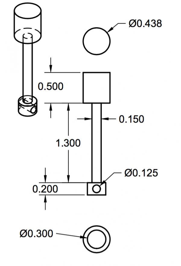
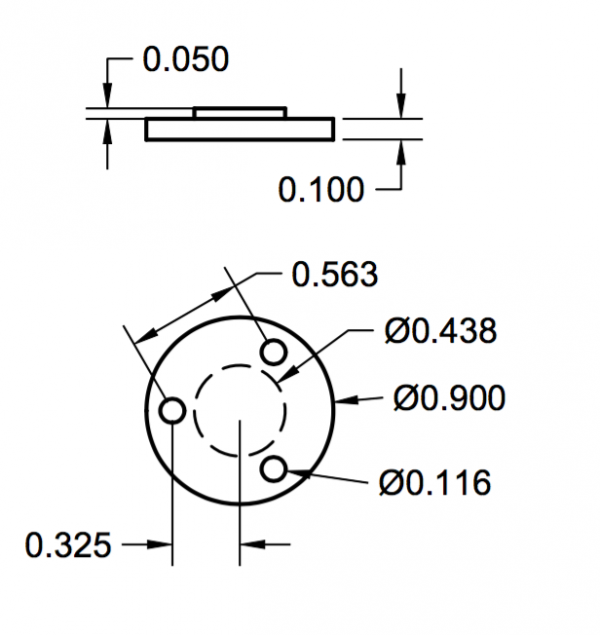
As before refer to the drawings for all dimensions in the parts you’re about to see being made. Here’s a look at the cylinder, to start with:
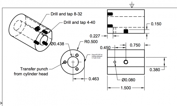
The cylinder starts out very straightforward- simply turn a piece of brass stock to dimension, face the end, center-drill, drill, and ream to the correct bore (as shown in the drawings).
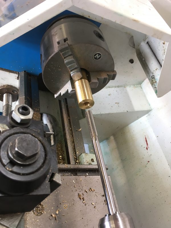
At this point you can flip the cylinder around in the chuck and face the other end. A secondary setup is fine for the facing operation, since we have achieved our goal of concentricity already. Here’s where things get interesting however. A cylinder needs to be mounted to something, right? Furthermore, once mounted, the piston needs to move inside it such that the end of the piston rod follows a precise linear motion relative to whatever the cylinder is mounted to. That’s why we needed concentricity in the cylinder- because the piston will be moving relative to the mounting point of the cylinder, and if that system isn’t entirely parallel, something will bind (or leak).
To make matters even more interesting, the cylinder mounting area in a wobbler engine is also the valve system. That means we need a very flat surface for sealing, and that surface will be moving. The plane of that motion needs to be parallel to the piston’s travel, which means our flat surface needs to be parallel to the cylinder bore. This is probably the most critical operation in the whole engine, so it’s worth taking the time to get this right. The question is, how to we create a flat surface on the side of a cylinder with just a lathe? Easy! The four-jaw chuck. Recall from last time, we talked about how three-jaw chucks are precise but not repeatable. Well, four-jaw chucks are precise and repeatable! This is because the jaws are independent, and thus you can “cancel out” the runout in the rotational system formed by the spindle and chuck of the lathe.
Before we get into how we’re going to set up this cylinder-flattening stunt, let’s cover the basics of four-jaw chuck use. I would practice this before trying to do the funky setup on the cylinder. Here’s a crash course in the independent four-jaw.
The first step is to get your part centered in the chuck to within 100 thou. That’s one sweep of the indicator, and being within that makes this process way less mind-bending. With experience you can easily eyeball it to get it within 100 thou, but here’s another method. Align all four chuck jaws to one of the rings on the chuck- that’s what they’re for. Then, hold your piece in the opening, and tighten two opposite jaws the same number of turns of the wrench until they touch the piece, holding it lightly. Then do the same with the other two- always counting the number of wrench turns to keep them roughly equal. When all four jaws are touching the piece, we can move on to the indicator.
Now we’re going to spin the chuck by hand, always in the same direction. The mag-base arm will have a tiny bit of slack, and the indicator stem will have some drag on the surface. That means the system effectively has backlash in it, like the lathe cranks. Always turning in the same direction corrects for this. As you turn a full revolution, the indicator will tell you your highest spot (closest to the dial, furthest from you), and your lowest spot (furthest from the dial, closest to you). The distance between the two is how much we have to move the jaws.
“But wait,” you may be thinking, “how do I know which jaw to move, when the high spot could be anywhere?”. Aligning the indicator with one jaw allows us to pretend that the high spot is always aligned with a jaw, so we always know exactly which one to move. Let’s take a look at how this works. Below is a diagram of how the four jaws might be gripping the material, exaggerated for effect.
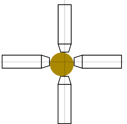

As you can see, only looking at the indicator when it’s aligned with a jaw will get you where you want to go, without having to do brainastics trying to move two jaws at once.
Make small turns on the wrench (10-15 degrees) until you get used to how much wrench turning maps to how many thou on the indicator. This will depend on your particular chuck and your particular indicator.
One or two iterations of those big moves will get you within 5 thou. Now it’s time to “tighten in”. Continuing to rotate in the same direction as before, turn until the indicator shows a low spot, and tighten the jaw facing you. Again, because of how the indicator is set up, the high and low spots will always align with a jaw. Each tighten should be to the midpoint between your high and low point, which by now should mean you need to move at most 2-3 thou.
If you do something and the run-out gets worse, that means you moved a jaw in the wrong direction. This is easy to do by mistake. Just stop, clear your head, and restart the process. The first time I did this process, it probably took 20 minutes. You get better quickly with practice, and I can now do it within a couple of minutes. Real Machinists™ can do it in 30 seconds or less.
After two or three iterations of the tightening-in, our runout is reduced to ¼ to ½ a thousandth. That’s plenty precise for anything getting built in Blondihacks Labs.
It’s also a good idea to go around one more time and make sure all four jaws are tight at the end. Do this carefully to avoid messing up your hard-earned setup. If the tightening-in was done well, none of the jaws will be loose anyway.
What’s cool about this process is that the material we’re going to machine now has effectively no run-out in it, but the jaws will not necessarily be centered on the spindle. The process above has “cancelled out” any runout in the chuck, the jaws, or the material. The material could be a crazy shape, and we can still dial in the exposed part to have zero runout. This is the magic of the four-jaw, and the reason your lathe cannot be without one.
Okay, with four-jaw basics covered, let’s get to a more creative use of this awesome chuck.
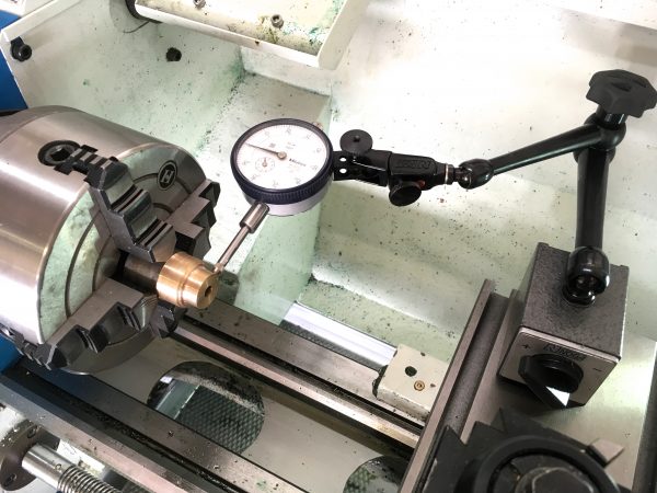
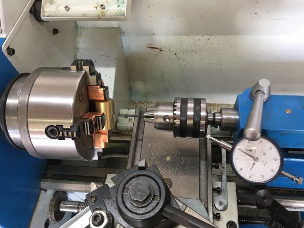
Because the outside of the cylinder is machined, it’s a valid reference surface. When placed against the face of the chuck, we know we’ll get cuts that are parallel to the bore inside, since we know we maintained concentricity between the outside and the bore. Tricky, but these are the mental gymnastics of machining.
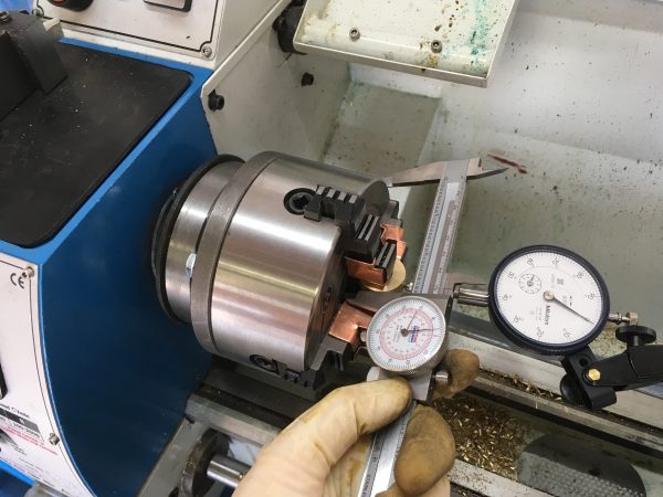
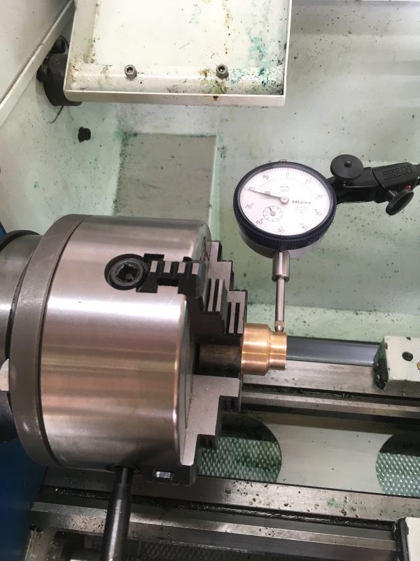
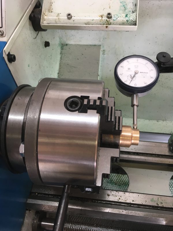
The four-jaw technique for centering the cylinder is the same for a normal part, by we need to do it twice- once for each axis. Start by eliminating the runout in the long end. When you rotate the chuck from one end to the other, pull the plunger out by hand, then let it touch the other end when you’ve spun the chuck 180°. Compare the two ends and make adjustments until they read the same. Then do the same for the short sides, to get the center of the side of the cylinder right on the center axis of the lathe.
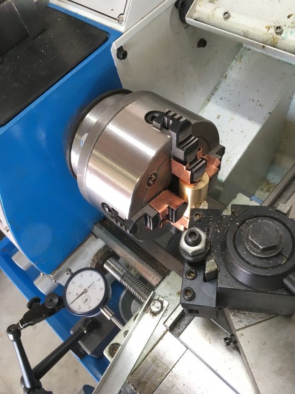
With the cylinder in this position, we do a normal facing cut to the depth shown in the drawings. It will be as though we’re facing off a large round bar with a diameter the same as the length of the cylinder. This is an interrupted cut, so don’t get aggressive. Take your time and make as many shallow passes as needed to face down our flat side. Ten thou at a time for a small bench lathe like this is a good starting point.
At this point you may note that the cylinder has smooth sides (as called for in the drawings). This is the easiest way to make the cylinder, and is how beginners should do it. However you may notice in later videos that my cylinder has decorative ribs on it. This is because I made the cylinder twice. In my case, I botched the dimensions in a pretty unrecoverable way, and had to make the part again. Don’t be afraid to do this- it’s going to happen to you! Think of it as an opportunity to practice your skills. Making the part the second time always goes much quicker anyway, so the time lost is not as bad as it seems. You’ll learn something every time you make a part, so appreciate these growth moments for what they are.
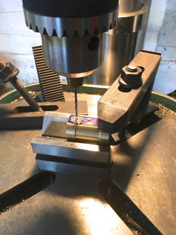
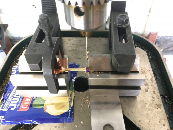
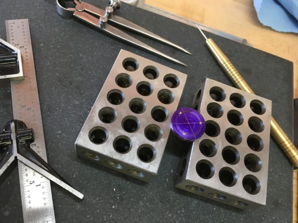
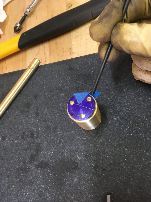
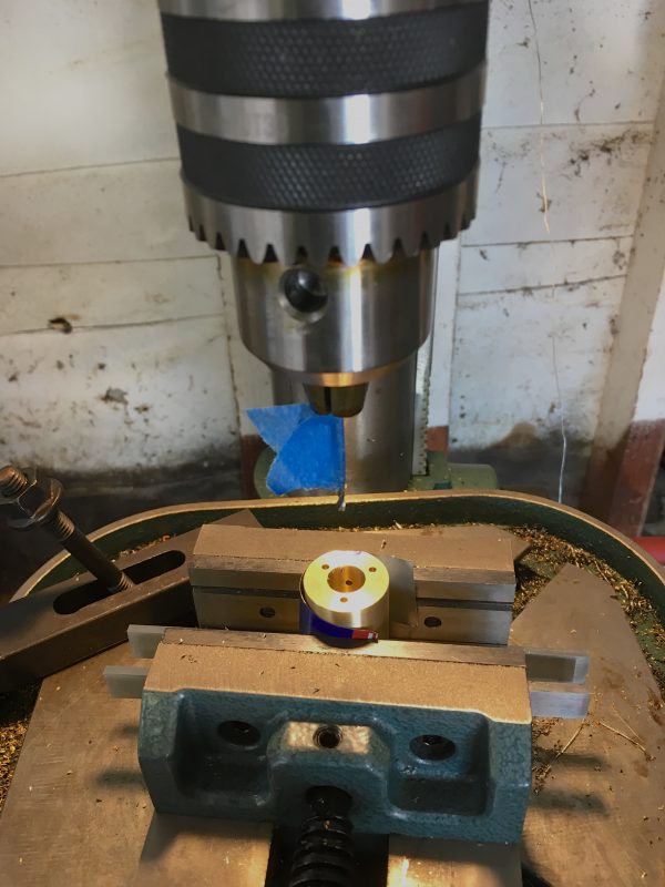
With the side flattened, the next step is to drill and tap the pivot hole. This is what makes a wobbler wobble, after all! Since we took the time to align the cylinder, we can now simply chuck up our center drill, knowing it will land right in the center of the flat spot- no layout required. Resist the urge to drill this hole on the drill press. We want to use the lathe for this to ensure the axis of rotation of the cylinder is precisely parallel with the crankshaft. The lathe will do a much better job of this than a drill press.
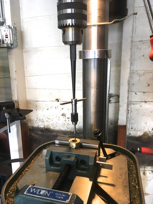
With that hole drilled, we can tap the threads for the cylinder pivot, as shown in the drawings. You will need a bottoming-tap for this. This is a blind hole that is much too shallow for normal taper taps. Tap on the lathe or drill press to get a nice straight thread.
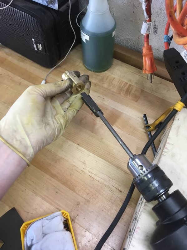
The last operation we’ll do is to hone the cylinder. The purpose of honing is to get as smooth a finish as possible in the bore, thus ensuring a good seal and friction-free operation. In some cases, such as internal combustion engines, the hone also helps retain oil on the surface (via a cross-hatch pattern achieved with a special machine).
A serviceable cylinder hone can be made with a scrap of round bar. Cut a slot in the end, slide in a piece of folded emery paper, and chuck the whole thing in a hand drill. This creates a high-speed abrasive that you can run up and down the cylinder. Start with 400 grit, then go to 800, then 2000. If you’re feeling ambitious, you can finish by stuffing a piece of rag in the honing tool, saturated with brass polish.
Next up, the piston! Making the piston itself is a pretty straightforward turning operation. There are a few details that are interesting to cover though.
The final step is fitting the piston to the cylinder. Back into the chuck it goes, but we’re not going to be using any cutting tools.
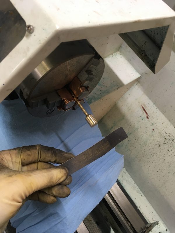
Wrap the emery paper about 90° around the back of the part, holding it lightly with your finger tips. In the unlikely event that the lathe grabs it, you want the paper to be pulled out of your hands, rather than your hands getting pulled into the chuck. Sand the piston for several seconds at a time, with the lathe at a moderate RPM (perhaps 400). Test fit against the cylinder with each pass until you get the right fit. Then polish with 800 and 2000 to remove the scratches from the 400 grit paper.
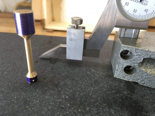
The “right” fit in this case is that the piston slides easily, but when you remove it quickly, you hear an audible “pop”. To test this, cover the steam port and the top of the bore with your fingers. Slide the cylinder over the piston, then slide it off quickly. You should hear a pop like a cartoon bubble popping. Also remember that oil occupies a little bit of space, so test fit with the piston lightly oiled with a 3-in-1 machine oil. When you’re done, the piston will be loose enough that it can fall out of the cylinder from its own weight, but still audibly pops when pulled out quickly. If you’re unsure, err on the side of the piston moving more freely. If it leaks a bit, that’s okay- you can add more steam pressure to compensate. The engine will be less efficient, but will still run. On the other hand, if the piston is sticky or binding at any point in its travel, the engine won’t run.
The last part we’ll throw into this post is the cylinder head. This is a very straightforward turning operation, so I won’t show that here.
Make sure the cylinder head bolts don’t align with the steam port! You don’t want them interfering.
Okay, that’s all for now. The hard pieces are made, and we’re in the home stretch. Soon we’ll be able to start assembling parts into something that resembles an engine! This is the point at which we begin to salivate at the thought of an engine running under its own power. Grab your bibs and stay tuned!