An automatic stint timer for endurance racing
My crazy friends and I regularly compete in something called The 24 Hours Of LeMons. It’s a somewhat tongue-in-cheek form of low-budget endurance racing involving cheap cars, heroic repairs, wacky themes, and a lot of serious driving. We’re The B-Team, and our current theme is Kill Phil. The theme is a bit of an inside joke, which I’ll spare you the details of. Anyway, LeMons is a great way to do some real endurance racing at a very low cost, in a fun atmosphere. It’s been called “Burning Man with roll cages”, which is pretty apt.
We’ve done about a dozen races over the past couple of years, and one of the things we found ourselves wanting is a stint timer in the car. If you’re not familiar with endurance racing, the format is simple. The cars race around the track continuously for a set amount of time (usually 12 or 24 hours), and the goal is to complete as many laps as possible in that time. Each team has four or so drivers, who take shifts of up to four hours in length (or one tank of fuel, whichever comes first). When a driver’s stint is over, they come in, and we perform a “pit stop”, whereby we refuel, change drivers, and freshen up the car as needed, as quickly as possible. Fast pit stops are critical, because while your car is in the pit, everyone else is out there earning more laps.
Endurance racing is very hard work- imagine running a marathon while doing long division in roman numerals. When you’re in the car, it’s important to relax and pace yourself. To that end, it’s nice to know how far into your stint you are, and how far into the race the team is. With a stint timer in the car, the driver can get this information any time, without having to bother the radio operator (who has plenty to worry about already).
So, the goal for this project was to build a timer that showed elapsed time for this session, and overall time of day. It also needs to cost very little, because this is LeMons, and it’s all about doing things on the cheap. You might say we could do this with a stopwatch in the car, but the problem with that is that someone (the pit crew or driver) would need to manually reset it during pit stops. These races are literally won and lost by cumulative seconds spent in the pit, so any extra little task on the pit-stop checklist would be a real burden on the team’s performance.
What’s needed is for the clock to start automatically when the car’s ignition is fired (marking the stint start), and automatically reset when the car shuts off (marking the stint end). The car is always shut off during pit stops, so this is a convenient way to bracket the stint times. The clock also needs to run on its own power supply, since the car’s entire power system is shut off during pit stops for safety. Race cars have something called a “kill switch” which is a big red lever that is thrown during refueling. This lever disables every last bit of electrical source in the entire car. The clock needs to run on batteries to avoid being reset to midnight every time the kill switch is thrown.
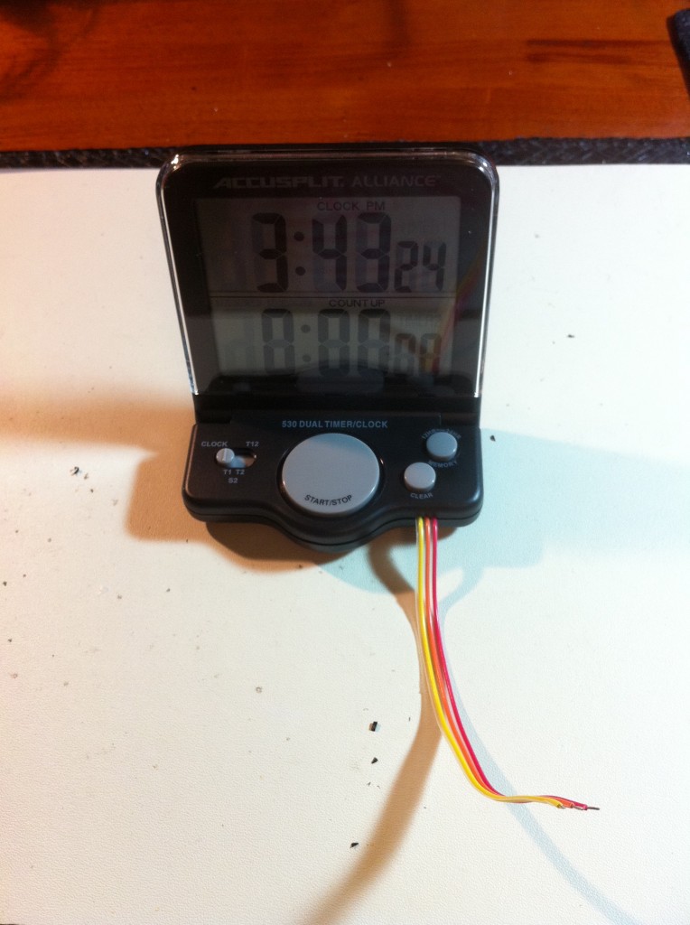
Commercial solutions to this problem are very expensive- into the hundreds of dollars. However, I found this dual-time/stopwatch clock for $20 online:
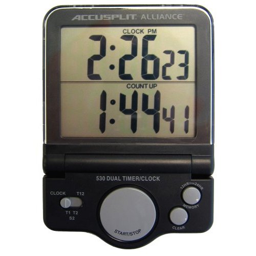
That clock was really close to what I needed- it has time of day on top, and a stopwatch on the bottom, all on one display with huge numbers. It even has large-size buttons, which would be operable when wearing Nomex gloves (such as when driving or fueling).
All that was needed was to automate it. It’s hackin’ time!
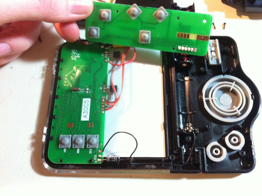
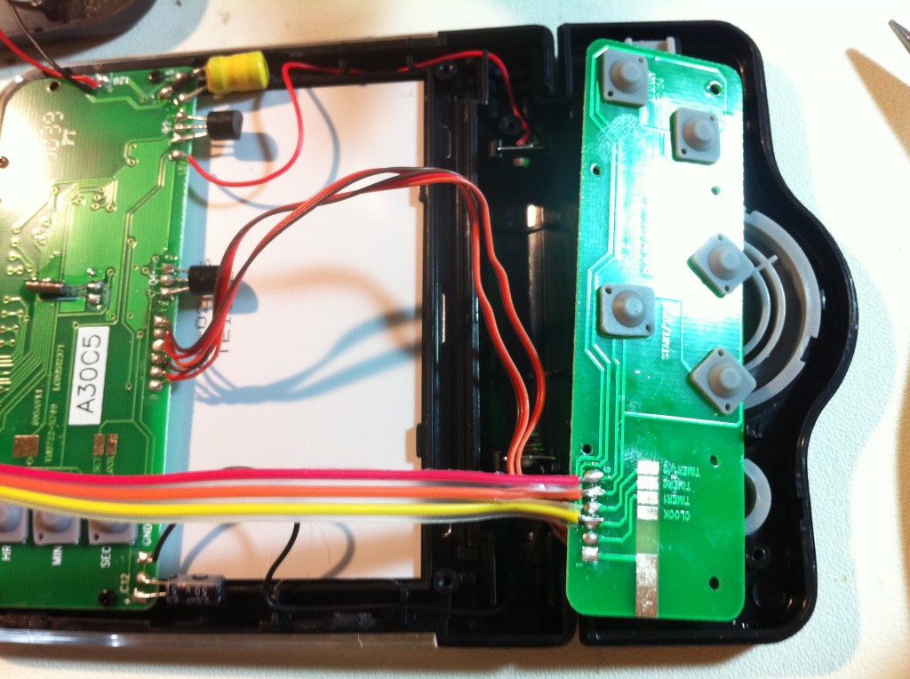
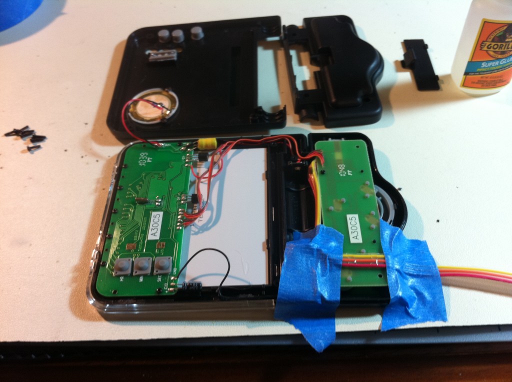
Now that I knew I could control the clock the way I needed, it was time to develop a circuit that would actually do it! I opted to control the buttons via some little DIP relays I happened to have. I bought a bunch of them at a surplus store a while back, and they’re really nice. I like that they will keep the control circuit physically isolated from the clock, as well. Since the two circuits are on their own grounds and their own power levels, this seems like a good idea.
The operational sequence goes like this- assuming the car is out on track, the timer will be running. The driver will come in to the pit at the end of their session. When they do, they will shut off the car. I need to detect that, then stop the timer. When the next driver is in and ready to go, they will start the car. I need to detect that, and respond by resetting the timer and starting it again.
Here’s what I came up with to do that:
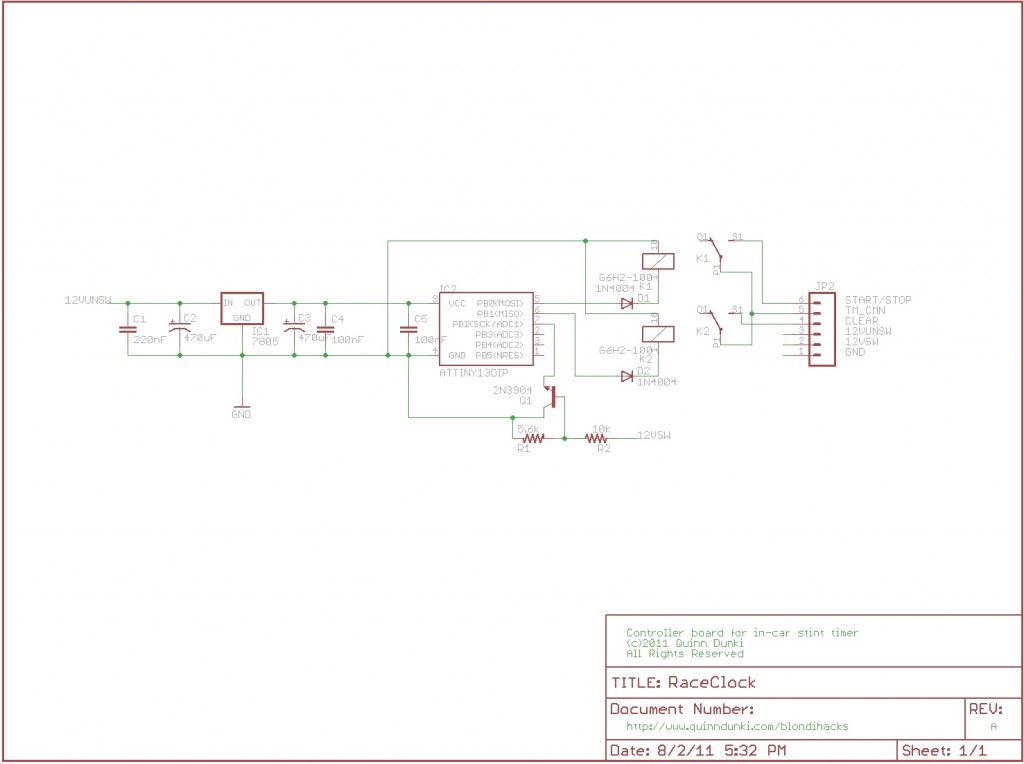
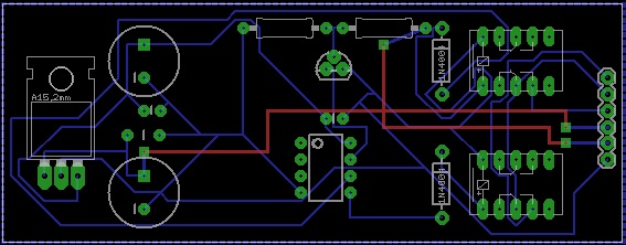
Here’s the Eagle schematic file, if you’re interested. As you can see, the logic runs off the car’s power. The clock is on batteries to be protected from the killswitch, but I wanted this add-on device to be zero-maintenance. One less thing to go wrong is always a plus in endurance racing.
The relays are driven directly from the MCU’s output pins, because they draw very little current. I put diodes in there to protect the MCU from inductive blowback. The car’s 12V ignition power is fed into a voltage divider to get it down to 5V, then into a transistor which pulls an input pin low. This will tell the MCU when the car is running, and when it has stopped.
The code on the MCU is trivial:
[iframe_loader src=”http://pastebin.com/embed_iframe.php?i=KNFhKXq6″ height=”600″ scrolling=”yes” marginheight=”50″]
If you’d like to use this code, here’s the source, and a compiled binary. This is for the ATTiny13A.
One thing to note in the code is the three second delay at the beginning. Starting a car is rather like an electrical hurricane. This delay before the logic sequence begins is to give the car time to start, and time for the electrical system to settle down. You’ll also see some small delays amidst the relay pulses. The clock is a pretty primitive thing, and can’t handle really rapid button presses. The relay sequencing needs to be sluggish to keep from overwhelming the cheap clock’s logic.
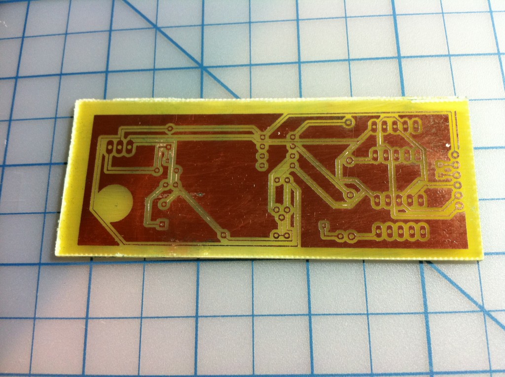
Since reliability is critical here, an etched PCB was in order:
Here’s the Eagle PCB file, and an acetate of the traces, if you’d like to etch your own. I etched the board myself using this process, which I’ve had very good luck with in the past.
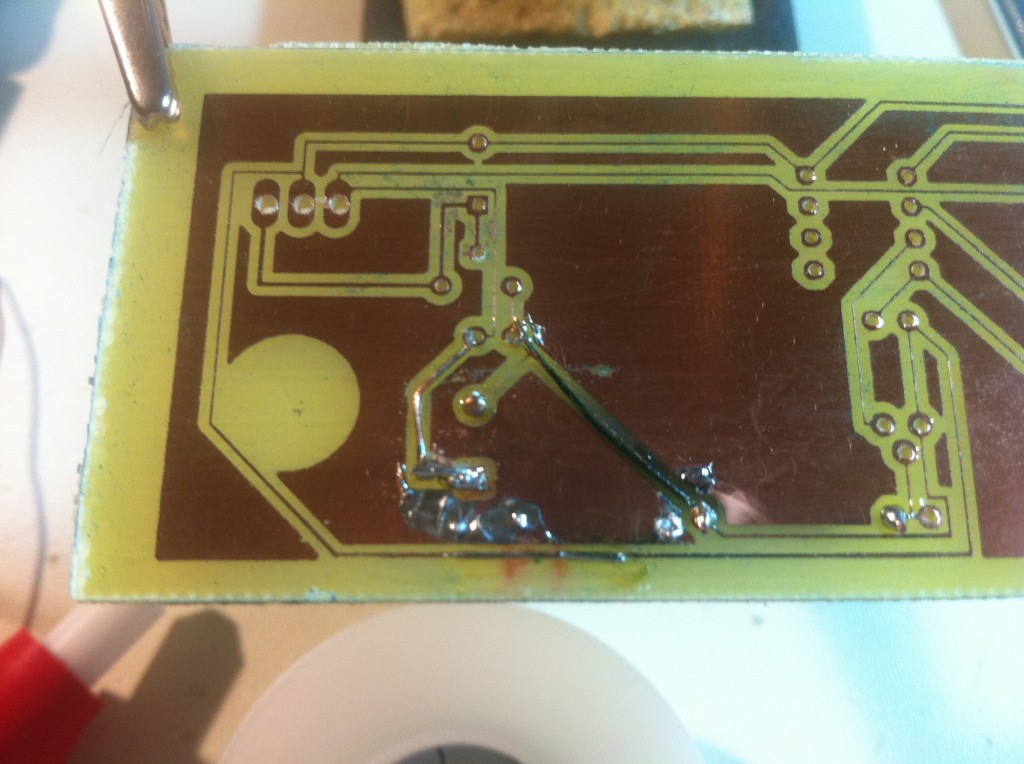
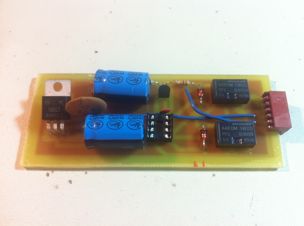
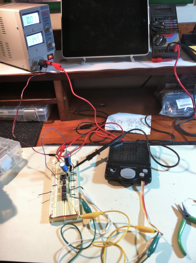
The circuit is built, the microcontroller is programmed, so we’re ready to go, right?
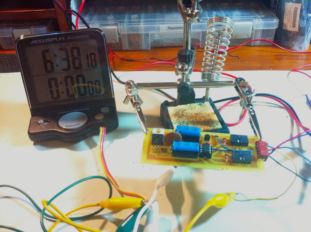
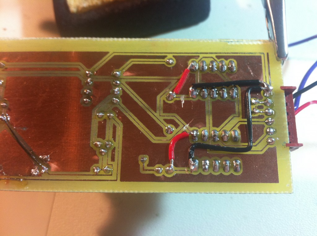
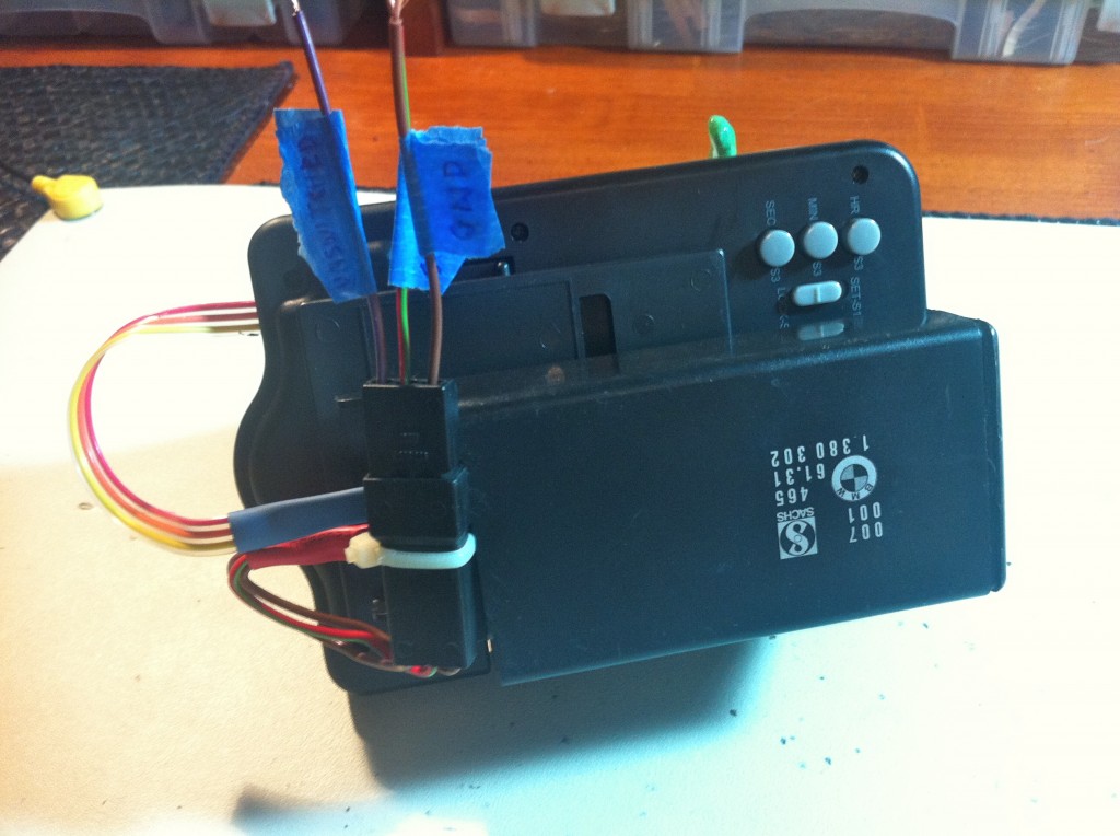
A little bit of tracing with a meter revealed the problem:
Here’s a little video of the device in action. My finger is simulating the car ignition. Note that when the car starts, there’s a few seconds of delay, then the timer is reset and started. When the car stops, the timer is stopped.
Here’s video of the device in the car, with yours truly getting ready to head out on track. This is the start of the race day, not a mid-race pitstop, hence the apparent lack of rush. The clock is mounted to the rollcage, on the right-hand windshield pillar. When I start the car, notice there’s a brief delay, then two beeps. Those beeps are the clock resetting and starting again.
That’s all there is to this gadget. We’ve used it for one race so far, and it worked perfectly. Hopefully it will continue to do so for many racing seasons to come. See anything you’d change in the design? Want to make fun of my ghetto PCB? Let it all out in the comments, below!
Want to see more video? Check out The B-Team YouTube channel and The-B-Team Facebook Page.
One thought on “Race Clock”
Comments are closed.