Getting our boiler shell ready to work on.
We demonstrated last time that D.E. Johnson’s old design for an automatic electric boiler should indeed work with the modern components we were able to source. Let’s get to work actually building the thing, starting with some basic prep on the shell.
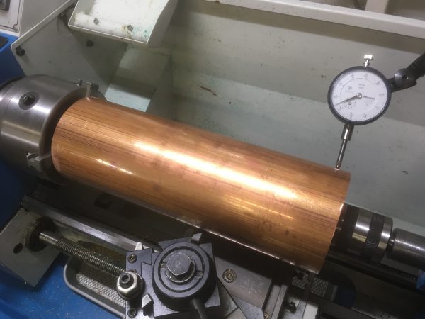
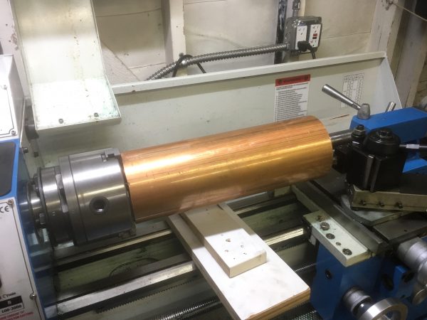
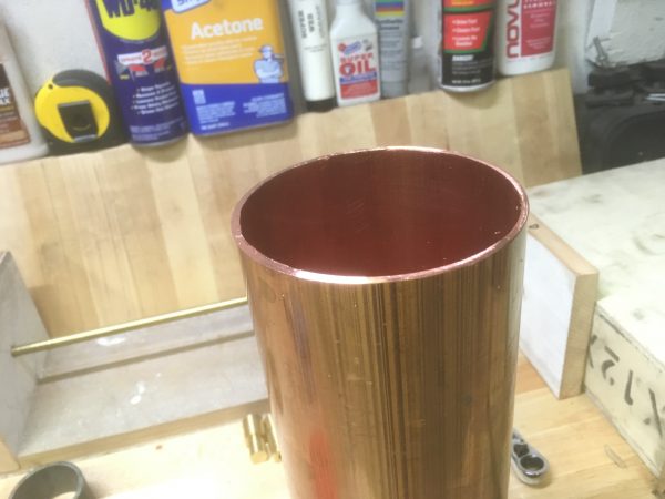
As previously identified, the shell is a piece of 4″ Schedule L copper water pipe, 12″ in length. This should give us plenty of steam to power engines up to (and possibly exceeding) a 1″ bore. Getting a hold of this piece of water pipe might have been tricky prior to the internet, because metal suppliers generally want to sell you things in 20′ lengths or so. Since this stuff runs about $80 a foot, and we don’t fancy making twenty boilers, that’s not a great option. Finding an off-cut is the way to go, but I’m honestly not sure where I would go locally for this. Perhaps a plumbing supplier that serves multi-dwelling construction companies? I don’t know what 4″ copper pipe is used for. Someone who needs a whole lot of potable water in a hurry. Anyways, here in the lazy internet age, it took me about four clicks on eBay to find exactly what I needed. Whoever said life used to be better in the olden days never tried to source one foot of 4″ Schedule L copper water pipe.
Since the ends of the pipe are saw-cut, I thought it would be nice to square them up. This is probably not strictly necessary, but it seemed like an interesting challenge and might make fitting the heads easier later.
My first attempt involved files. Copper files just fine, but after 20 minutes or so of effort, it was clear this wasn’t going to be a good way to go. It was going to be very difficult to get it square all the way around with simple 1″ wide files and my lack of hand-eye coordination.
My next thought was sanding. The cut was overall pretty square, it just had high and low spots in it (probably made worse by my attempts at filing). If I could sand it flat, that might be good enough. Depending on where it ends up, I might also be able to get it square from there.
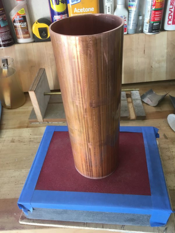
Sanding was working, but it was a lot of work. Copper is very soft and sticky, so any kind of abrasive process gets tiring in a hurry. It was like pushing a sack of potatoes around on a sheet of velcro. The task was sufficiently physically demanding that I wasn’t going to get anywhere fast. The results were better than filing, but it was even slower and more tiring.
The obvious candidate for this job is, of course, the lathe. I had been dancing around this, since there wasn’t an obvious way to fixture it. I decided that rather than dedicate my muscles to sanding, I’d prefer to dedicate my brain to solving the fixturing problem. Afterwards, I will dedicate my liver to processing fine whiskey. Each organ has an ideal purpose. Now then, if I can get it mounted in the lathe, the machine will do all the work and I’ll end up with something both flat and square.
The lathe operation required is facing, so we need to get it mounted such that one end of the tube is exposed at a right-angle to the tool bit, and reachable by the tool post. The chuck end is pretty easy- I can grip the insides of the tube by expanding the three-jaw chuck jaws. It was the far end that was the challenge. I couldn’t rely on the chuck alone to hold such a large piece. The other end needed support. A steady rest would be a good choice here, but mine is much too small to fit around a 4″ diameter pipe. That left the tail stock. Of course, we’re dealing with pipe, not solid stock, so the tail stock has nowhere to go.
If I could come up with some sort of insert that would fit tightly inside the pipe, the tail stock could then be centered on that, and thus support the piece. This supporting insert must be a tight fit on the inside surface of the pipe, because it needs to hold against the cutting forces of the facing tool. Since this is a large diameter and copper is very sticky, those cutting forces could be considerable. A simple method might have been to cut a circle of wood sized to be a very tight fit, and hammer it into place. I considered that option, rejected it as way too likely to work, and set about doing something pointlessly complicated.
I’ve made plenty of hay on this blog about how 3D printers are kinda overrated, and how I’ve really struggled to find uses for mine in the two years I have owned it. In addition to being endlessly fussy and requiring constant tweaking, the parts that (very very very slowly) come out of it are sometimes interesting but mostly imprecise plastic junk. For most things, in my cynical opinion, other methods of production or repair are faster and result in a better component. That attitude is not particularly fair, however, because these machines definitely have their uses and I am finding niches where 3D printing is just the thing. My primary use (not counting the “finding excuses to use it” type of project) has been project boxes for electronics. This is not as trivial as it sounds. Making enclosures suited to a homemade circuit board with all the various openings for LEDs, ports, etc, is not easy. You start with some prefabbed box bought at McMaster (previously Radio Shack- moment of silence…), then go to town with drills, files and old soldering irons, trying to cut, beat, and melt it into something like the shape you need. 3D printers are a brilliant solution to this problem. You can get exactly the enclosure you need for very little money, and the end result looks pretty decent.
All that is to say that lately I’ve been finding a new niche with tangible positive results. It seems that machine shop work is a great compliment to 3D printing. Machine shops have a set of chronic challenges that 3D printers are really great at solving, including organizing weirdly shaped things, and producing weirdly-shaped brackets to hold things. The latter is what we’re on about this time. Can I 3D print a tail-stock fixture to hold the 4″ water pipe sufficiently securely for a facing operation? Let’s find out!
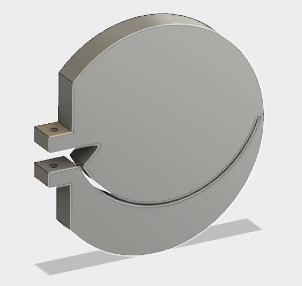
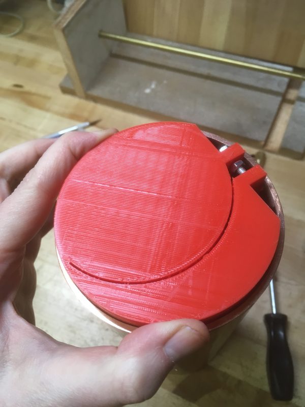
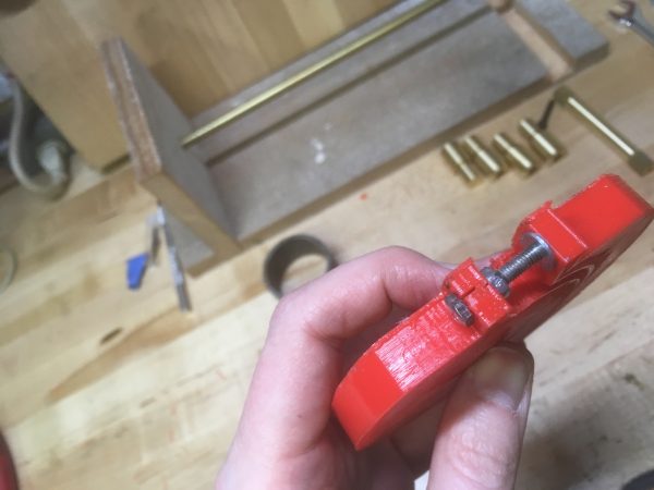
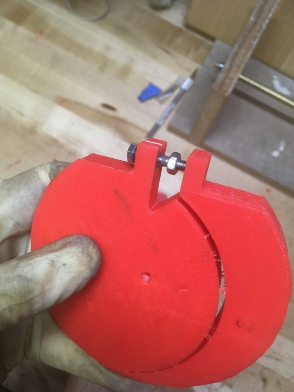
I got a picture in my head of what this fixture could look like. It needs to be round (no, for reals), have a solid area in the center for the tail stock to go, and it needs to be expandable. This last bit is key- we need to be able to tighten it inside the pipe, because we’re relying on friction alone to hold it in that pipe against all the forces applied by the cutting tool and the tail stock. I wasn’t sure if 3D printing was up to the task, but it seemed fun to find out. I knocked out this design in Fusion 360:
This seemed definitely too stupid to work, but that has rarely given me pause in the past, so off to the PrintrBot we go.
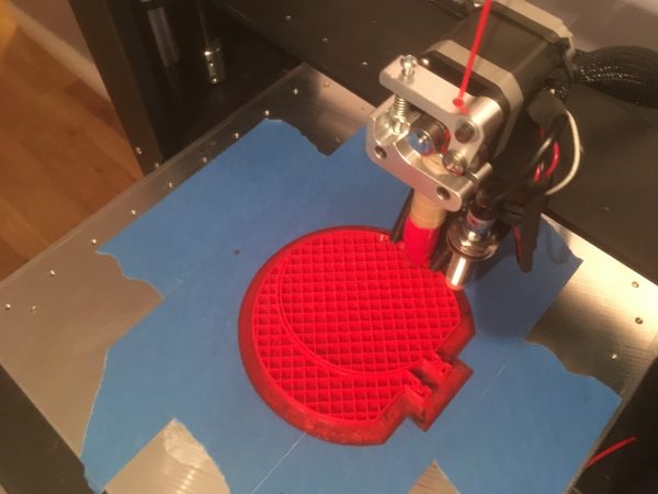
These days I have my PrintrBot pretty dialed in, so when I ask for a dimension, I generally get it (within the tolerances of plastic squeezed out of a glorified pastry bag). That was the case here as well, luckily.
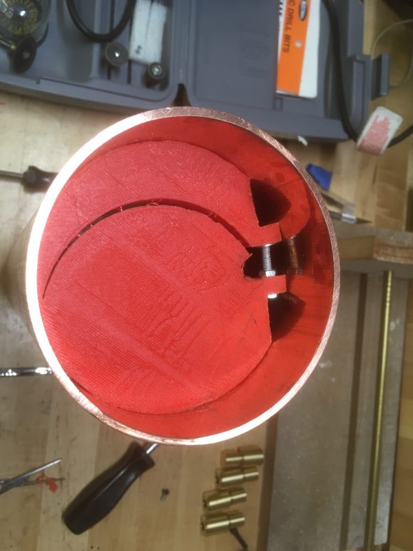
The expansion works by inserting a bolt through one tab, and letting it seat in a blind hole in the other tab. A nut is threaded between the tabs, and loosening this nut applies outward pressure on the tabs, expanding the joint and tightening the fixture inside the pipe.
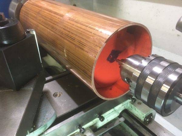
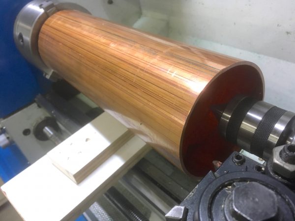
In order for the tail stock to apply support to this fixture, it needs to be center-drilled. The support will be in the form of a live (ball-bearing) center in the tail stock. 3D printing is nowhere close to precise enough to include a feature like a center-drill, so I did this after the fact. With the fixture installed tightly inside the pipe, I set it up in the lathe to prepare for center-drilling.
Being supported only by the chuck like this is pretty precarious, but it only has to survive long enough for a center drill, and that’s a very low-tool-pressure operation.
Okay, time to give this a shot!
The next question was what kind of tool bit to use for this? It’s well known that copper is very difficult to machine. It’s so darned soft that it’s like cutting butter with a bowling ball. Sure, you can do it, but the ball will be a mess and who wants that butter on their toast when you’re done? Okay, that metaphor kinda got away from me there, but the point is copper is tricky. I figured it was going to be similar to either aluminum or brass, both of which are also soft and have unusual tool grinds required as a result. Aluminum is gummy and brass is grabby. Aluminum needs a very steep top rake on the tool to cut in and start a chip through the gumminess. Brass is the opposite- it needs zero top rake in order to keep from getting grabbed and sucked into the material. Which one will copper be like? I could have probably looked this up, but instead I guessed and mounted up my brass-angled facing tool. I was mistaken- turns out an aluminum-angled tool would have been the right choice. In any case, my tool did actually work okay, although it was a pretty tense operation.
Here’s how it went:
I went very slowly and took extremely light cuts- 2-4 thousandths at a time. You can hear it rubbing towards the end because of my poorly-chosen top rake angle, but a lot of that noise is also just the softness of the copper combined with it being an interrupted cut (since we’re squaring up a rough saw line).
I managed to get one very very close to squared up all the way around, but the stresses on my 3D fixture got too high and it popped loose.
Turns out it was a bit worse than it first appeared- my fixture experienced a key structural failure. For the other end of the pipe, I printed a new fixture at a higher infill, to hopefully get more strength.
I knew this would be a weak point of the design, but aside from printing the piece solid, I wasn’t sure what to do about it. I wish 3D printer slicing software had a way to designate a particular area to be solid. The vast majority of the piece doesn’t need to be that strong, but if I could print those tabs solid, it would be the best of both worlds. If anyone knows a way to do this, let me know in the comments so I can level-up my 3D printer-fu.
My second print at 40% seemed to hold up about the same, and it survived long enough to face the other end of the pipe.
Despite all the drama, the end result was pretty darned good.
This was a pretty interesting exercise in pushing my lathe, my 3D printer, and the laundry soap I use for my underwear to their limits. Since then I’ve found other interesting uses for my 3D printer in the machine shop, including these:
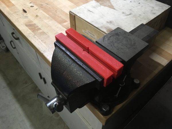
The second tool is one that mrpete222 has been showing on YouTube. It’s a 3D printed indicator holder for the tool post. This is a very quick way to get an indicator next to the work for dialing in a four-jaw chuck, bumping in a three-jaw, measuring runout, checking surface flatness, etc. Very handy! Unfortunately, his version was built around a small Shars indicator of a specific type, but I prefer a full-sized indicator. His thingiverse item only includes STL files, which is a bummer. It’s always disappointing when people don’t include their original model file from whichever 3D package was used. STL files are like binaries in an open source project- great if it’s already exactly what you need, but useless if it isn’t. Anyways, with his as inspiration, I was able to remodel it in Fusion 360 in about 10 minutes. I often forget how fast modeling is in Fusion 360, and I waste a bunch of time trying to massage other peoples’ STL files to do what I need, instead of just doing it myself.
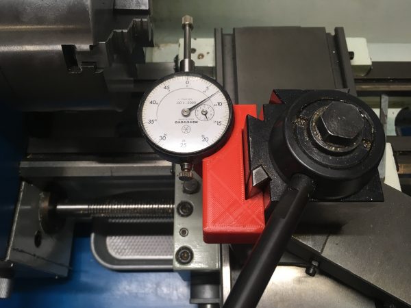
If you’d like my version, it’s here on thingiverse, complete with Fusion 360 source files so you can modify it for your indicator or tool post as needed. This tool is a good example of where 3D printers accel- it’s a very weirdly shaped thing, needs to be customized to my specific situation, but it doesn’t need to be super precise or super strong. The more I look around the machine shop, the more little things like this that I find!
Okay, that’s all for our boiler for now. With the shell in shape, we can get started building the parts. Stay tuned for heavy machining content, coming your way.
Instead of using a cutting tool to face up the copper, would it make any sense to use some sort of abrasive block in the lathe? I’m just curious whether the cutting tool was too “grabby” and that’s why the 3d part kept breaking. Maybe an abrasive thingy (tech term there) would have more of a cutting surface and produce less stress on the part? I don’t have a lathe so maybe this is totally off base. p.s. Keep up the great posts!
What you’re describing is known as tool post grinding, and there is a place for it. It’s not good at removing material, but it is good for achieving a very high surface finish. It’s typically used for things like polishing bearing journals on a shaft to ensure a perfect fit.
For removing material, though, you need a cutting tool. The tool pressure can be controlled in a few ways- surface speed, tool bit grind, and depth of cut, for example. At the 2-4 thou depths of cut I was using, the tool pressure is very low. There really isn’t much tool pressure here, it’s just that 3D printed plastic is not very strong in the way I’m using it.
An abrasive would actually stress the fixture a lot more- think of all the friction. A lathe tool bit is a single point cutting tool. It’s removing material at a single point only (hence the name), which is an extremely efficient process.
“Laundry soap” LOL! How well I know that feeling working on my lathe or mill.
What’s the gnarliest thing you’ve had happen on a machine? Do tell!
If you stack both inserts on top of each other, with bolts staggered, the pressure should be be distributed over the entire inner insert by preventing section flex.
I could also just print a double-thickness one. I think the failure mode was caused by the cracking of the tabs due to the expansion pressure put on them. Until that happened, the inserts seemed rigid enough.
If the tabs cracked due to expansion pressure, the crack would have been at the bottom of the tab. Because the crack is on top of the tab, I would instead suspect centripetal pressure caused by the deformation of the tailstock-supporting leaf into the cylinder. Essentially, the tailstock was pushing directly on the hole in the tab, with substantial force amplification. It’s like that textbook physics problem of a student attaching her car to a tree with a rope and pushing the middle of the rope sideways to get the car out of a mudhole.
Printing it doubly thick would make the leaf stiffer, but would still leave the tailstock essentially pushing against the tab due to the split of the leaves. Stacking the inserts and rotating 90 degrees would place the center leaf of the outer insert across both leaves of the inner, supporting it on both ends with friction of the inner leaves on the cylinder walls, with the outer tab lying flat against solid support and so receiving very little force.
I don’t think you have enough information to say that. The tabs are orders of magnitude stronger in the lateral direction because there is a lot more material and no weak layer joins in the print. There are a lot of complex forces involved in this system, and the cause of the failure is probably a combination of things.
Many years ago, I had a cheap tool for, if I recall (it was the 70’s), spreading break shoes to get on the expansion piston. The good tool was made of steel, mine of plywood. I note the similarity of 3D printed and plywood. To prevent the expansion bolt from splitting the layers, there was a metal clip holding the layers together, and a note on the instructions about limited lifetime, as in “good for one or two uses”.
Again an interesting read, even with no interest in lathes at this time.
To make a part of a print solid, add pinholes to it. Hole walls will be printed with solid perimeters.
Oh that’s a good idea! Thanks for the tip!
Simplify3D lets you set different print parameters – including infill – for different groups of layers, which unfortunately wouldn’t have helped you here.
I like the pinhole trick. Neato!
>different groups of layers, which unfortunately wouldn’t have helped you here.
No, but you may have been able to split it into different “parts” which had their own print settings, and then printed them merged together.
I’m not sure how that works though, haven’t personally done it.
Have a look at how Kent does it: https://kvvcreates.com/#id33
Great ideas in there- thanks for sharing!
Great stuff!. I’m working on a similar model boiler project and was excited when I checked out the site and saw you were at the beginning of this adventure. Looking forward to hearing about your silver soldering experiences when you get to that point.
My shop is currently mostly woodworking so my solution to squaring up the copper pipe was using a non-ferrous metal blade in the tablesaw. Tiny copper chips EVERYWHERE, but it it did a nice job.
Yah, I’ve been thinking a LOT about that. Silver soldering the heads is going to be challenging. I’m thinking about preheating the whole thing in an oven to get it close to 500°F, so that I can get the seams to 800°F with the torch. The whole thing will be such a massive heatsink that I think the brazing will be difficult. I don’t have access to an oxy-acetylene torch right now, which would probably be the right tool for that job. Fake MAPP (Map/Pro) gas will have to do.
Regarding making parts of your 3D printed clamp stronger: I believe Slic3r has an option for modifier meshes that allow for adjustment of some print parameters in certain regions of the print. I have never actually tried it myself, but here is a link describing the technique on the Slic3r website: http://slic3r.org/blog/modifier-meshes
Quinn,
I wonder if instead you should have used a plywood or metal base, and then printed the “shoes” to go around the edges, sized to almost hold the inside of the pipe. Then you have all the stress in the metal parts (or on a T-nut in plywood), while the “shoes” (like those vise jaws you printed) hold the work.
You could also have done a split model, where you had two bolts applying pressure on each side. This might have halved the load on the plastic tabs. Basically, you print an arc for one side, and the matching infill for the center point, but they’re both split in half. The trick is building a generic jig which expands radially evenly, so the center doesn’t move.
And thank you so much for your blog, it’s a joy to read! Keeps me inspired to do more when I can as well. And I have total envy seeing how organized your shop and work areas are. Mine’s a disaster…
John
Interesting ideas! I particularly like the two-clamping-screw idea. I bet that would help a lot!
Honestly, I bet simply cutting a tight-press-fit piece of wood and tapping into the pipe would have worked great- no fancy mechanisms required. I just wanted an excuse to try this on the 3D printer.
Hey Quinn. Looking at the Simplify 3d spec sheet, I see it can do variable density like you were looking for. I balked at paying half the price of my printer for software to drive it (particularly closed source stuff), but it really does work very well. https://www.simplify3d.com/support/articles/different-settings-for-different-regions-of-a-model/
-JRS
Could you have strengthened that tab by filling the honeycomb portion of the tab with something like CA glue (assuming that is compatible with the plastic). That way you can print with the smaller infill, but that region will be effectively solid. It may even be more resistant to layer separation since the glue will bond to all the layers.
That’s an interesting idea- maybe while the 3D print is running, if you could catch it just before the top layer is printed. I think some advanced slicers allow you to set a pause point in the print for stuff like inserting captive nuts, and that would work great for CA glue-filling stunts. I may need to look into that.