When “compromise” just isn’t good enough.
Race car aerodynamics are a very complex thing, but there are some easy wins that can be had at a very basic level. One of those is rear downforce. For the purposes of this discussion, I’m assuming your race car is rear-wheel drive, of course, because you’re not a monster or a fool.
A rear wing on a race car is basically an upside-down airplane wing. The principle is that air moving over the surfaces exerts downward force on the rear suspension, which serves to increase contact patch on the powered wheels and thus improve vehicle dynamics in corners. In particular, this can be helpful in reducing understeer, improving throttle steering and increasing corner exit speeds. However, there are no free lunches in racing. A wing increases downforce, but also increases drag. That’s very bad on the straight parts of the track, where you want as little aerodynamic drag as possible. Cars use most of their energy pushing air out of the way, and in endurance racing this is very bad for both lap times and fuel range. A clever way to have your cake and eat it too is with an active spoiler. I don’t know about you, but personally I very much like eating cake and I very much like owning cake. An active spoiler is a device that creates downforce when you need it, but gets out of the way when you don’t. Many clever racing teams create devices to do exactly that.
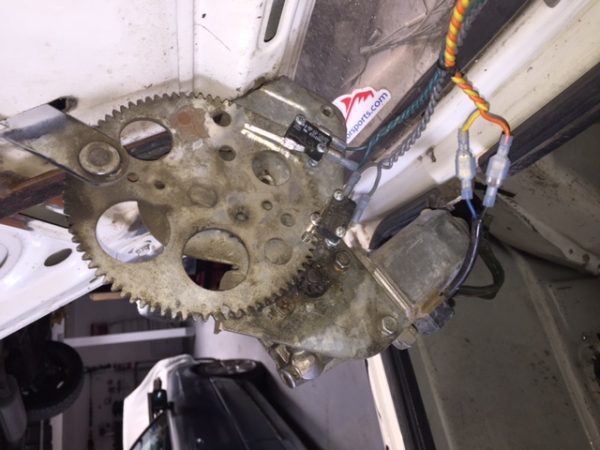
One such team is my good friends at Big Fish Motorsports, whom I know from 24 Hours of Lemons and Chump Car racing. They have designed a system for their car that moves the rear spoiler between two positions- angled upward for maximum downforce, and sitting flat for minimum drag. The spoiler is moved by linkages driven from power window motors. Simple, effective, and low budget. The motors are controlled by a home-brew electronic controller and ten(!) relays. Unfortunately, the system stopped working, and the original builder is no longer reachable. No schematics or source code were available. I was called in to help get this system back up and running again in time for a race in a couple of weeks. Time was of the essence! To make things more interesting, Big Fish is in a different city than I am, so I had no access to the complete system. They sent me the control box in the hopes that I can do something with it.
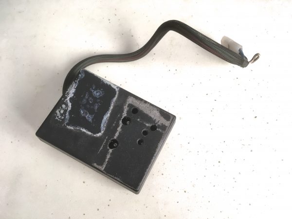
Now we have a dilemma. The logic of this device is clearly on the Arduino, but we don’t have the source code. We could dump the program memory on the AVR and disassemble it. The circuit looks pretty straightforward, and we could reverse-engineer that part. However, the configuration of the ten(!) relays is unknown, and that’s clearly key to this whole enterprise. I’m sure this system was designed this way for good reasons, and I’m inclined to give the original builder the benefit of the doubt. However, I can’t personally fathom what ten(!) relays were doing. Without being able to map all those connections out, we may not get far here. Still, let’s see if we can talk to the Arduino and find out what’s up.
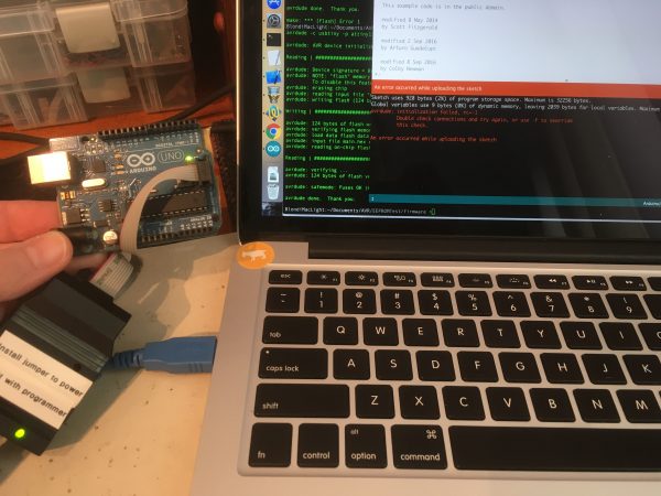
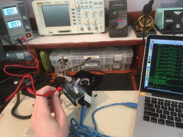
The Arduino IDE (integrated development environment) was refusing to talk to the board, so I tried avrdude directly on the command line. Same result- it’s not able to connect to the chip. There may be something wrong with the board, so I popped the AVR chip off and used one of my breadheads to try talking to it directly.
At this point, I need to start suspecting my tools, so I tested this exact setup with a known good AVR chip. That worked perfectly. It seems this AVR is either toast, or the fuses have been set to prevent reading anything from it. Either way, this is a dead end. We won’t be dumping the code and disassembling its secrets.
This may well be our failure point, so I can start by swapping in a new AVR. This is an Arduino UNO, which uses an ATMega324. Unfortunately, I don’t have one of those on hand, and there isn’t enough time to order one. However, the junk pile did cough up an ATMega168, and it has the same pinout. Some smaller/older Arduinos did use this chip, so the bootloader is compatible.
Now we’re getting somewhere. In theory, we can now lie to the Arduino IDE and tell it we have an older device, and get it to talk to the board. Setting the “board type” to “Duemilanove” in the IDE gives you the option to choose the older ATmega168 chip, since that model of Arduino originally shipped with it.
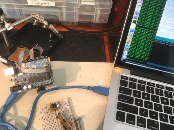
I should point out this is literally my first time touching an Arduino. It was pretty easy to get running, and I am impressed with the simplicity and rapid iteration of the programming environment. Of course, from years of working on my own AVR projects, I have developed an extensive set of libraries and macros that essentially do what the Arduino environment is doing. In any case, when in Rome…
At this point, since the original chip was unreadable, and I don’t have access to the ten(!) relay arrangement, the repair ship seems to have sailed. I won’t have enough information to reverse engineer this, and time is running short. It’s going to be quicker to reimplement the functionality that Big Fish wants, using the parts I have on hand.
The desired behavior is as follows:
- The spoiler rests in the down (flat) position, and should go there whenever possible
- In braking situations (such as entering a corner), the spoiler should move to the upper position.
- In some other situations, the driver may deem it valuable to have downforce, and thus has a button on the steering wheel which should move the spoiler up when held.
- There are two limit switches, one for each spoiler position. These should stop spoiler motion in the respective direction, to protect the mechanical parts of the system.
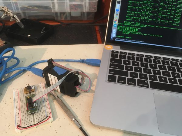
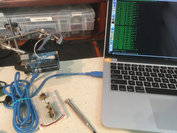
The logic portion of this is easy enough, so I mocked it up with the Arduino, using buttons to mimic the inputs, and LEDs to mimic the motors moving up or down.
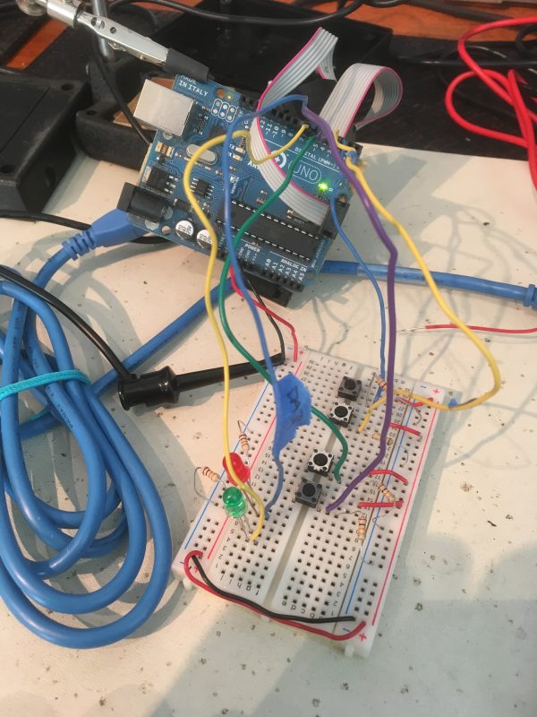
In typical Arduino-project fashion, the code for this is very simple. In fact, an Arduino is ridiculous overkill for this logic. We could probably do this with a couple of 555s or D-flipflops. But hey, we’re here, we have the parts, and this is fast.
The next challenge is power supply. Arduinos run on ~9V, and the logic needs 5V, but cars provide a really terrible 12-15V. I say “really terrible”, because cars are like an electrical hurricane. The source of the voltage (an alternator) is a very noisy AC device, and no effort is made to quiet anything down. You also have huge inductive loads all over the place, not to mention spikes from starting the car, charging the battery, jumpstarting if the battery dies, etc. In short, putting an Arduino in that environment is like taking a kid who is really good at Call of Duty and dropping them on Vimy Ridge in 1917. It’s the same in theory, right? Have fun, kid!
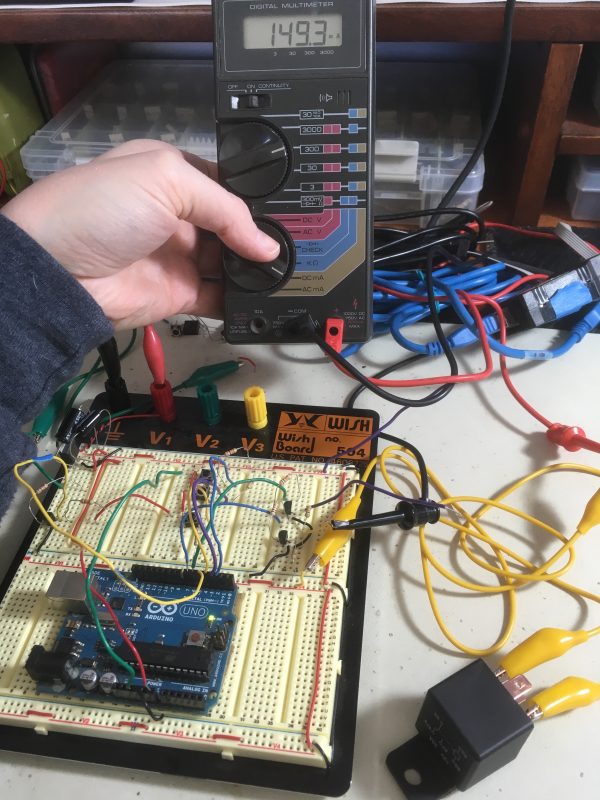
No, we need to protect our poor Arduino with a filtered power supply. I had some 7809s on hand, so I dropped one of those in (with lots of filter caps) to power the Arduino from the car. The Arduino itself has good regulation on board and can supply the 5V logic. Automotive voltage levels are pretty unpredictable, but typically they are 11-12V when the car is off, and 14-15 volts when the car is running (and the alternator is charging). I ran all my tests with the bench supply at 14.5 volts to simulate the most stressful condition. Luckily, the 7809 dissipates this extra power without even getting warm.
That’s all fine and dandy, but we don’t need to control LEDs. We need to control high-amperage automotive relays that run electric motors with enough torque to break your arm. Not only that, but there’s another gotcha here- we need a way to reverse the polarity on the motors in order to change their direction. Having an “up” and a “down” output as shown in my prototype won’t actually work.
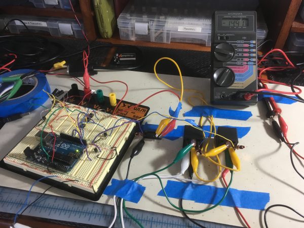
First and foremost, automotive relays are big. The coils alone draw a lot more current than an Arduino can drive, so we’ll need some transistors to do the job. The junk pile provided some salvaged 2N3904 NPN dealies that may be up to it. These are small signal transistors with a current limit of 200mA, however, which I wasn’t sure was enough.
When driving relay coils, you need to be aware of the damaging effects of an inductive load that changes state rapidly. When the coil shuts off, the magnetic field collapses back into current, and that energy has to go somewhere. If you don’t give it a better option, it will go back into your transistor, and spike it. Over time, this will burn out the transistor. We prevent this with what’s called a “flywheel diode”. This is simply a standard diode placed across the coil terminals. This gives the “back current” a path to run around in circles during the field collapse instead of backing up into your control circuit and beating things up.
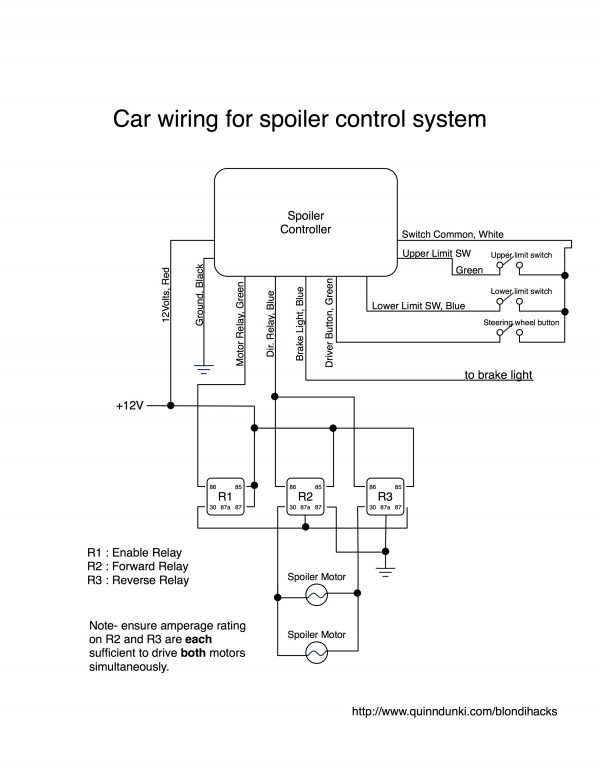
With that sorted, we can solve the problem of reversing the motors. This can be done with a simple trick from robotics- using two relays wired back-to-back to reverse the input voltage to the motors, and a third relay to control power to both, so we can stop the motor. Note that you can also do this with a single DPDT relay wired in a reversing configuration (along with the start/stop relay). However, this is for an endurance racing car, and a critical factor in endurance racing is ease of finding parts. Standard SPDT automotive relays can be found in every parts store in every podunk town at every racetrack in the country. Exotic DPDT automotive relays are quite uncommon indeed, and you wouldn’t want anything relying on a part you can’t get in a pinch.
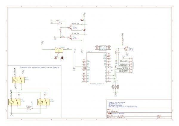
Using a transistor (and flywheel diode!) to drive each relay, I had a final setup that should do the job.
The next problem to solve is how to detect when the car is braking so we can automatically raise the spoiler. A switch on the brake pedal would be one way, but there’s something easier. Since this is a rear spoiler, it’s physically close to something that tells us when the brakes are applied- the brake lights! We can take a 12V signal from the brake light circuit to tell us what we need. However, our Arduino logic is 5V, so we can’t just plug it in and go. I opted to solve this by using the 12V signal to drive the base on another 2N3904 transistor, which would in turn drive a 5V logic signal on the collector-emitter (which is pulled low otherwise). This isolates the voltages from each other and gives us the logic level we need. This has the added advantage of being robust in the face of highly-variable voltages coming from the car.
Here’s the Arduino code driving this arrangement:
Along the way, I decided to document this project so that if the team needs someone else to repair or modify this in the future, they’ll have what they need.
I also created an automotive-style wiring diagram (which use different conventions than electronics schematics). These typically mark the wire colors, and importantly use the automotive convention for relay pin numbering. These relays come in a couple of standard configurations, and the pins are numbered in a standard (if odd) way that car people will know.
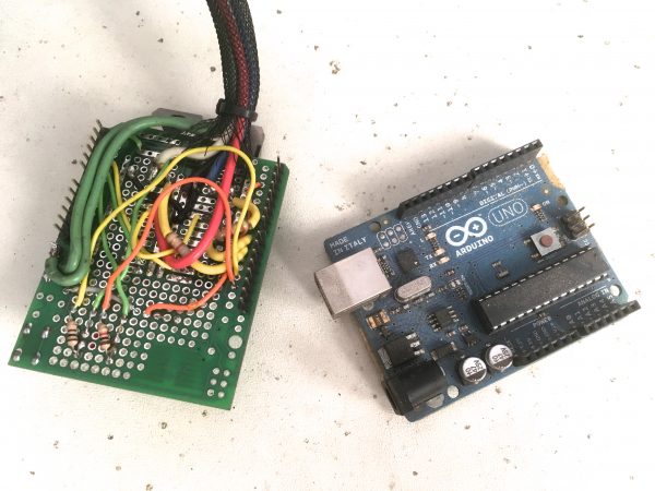
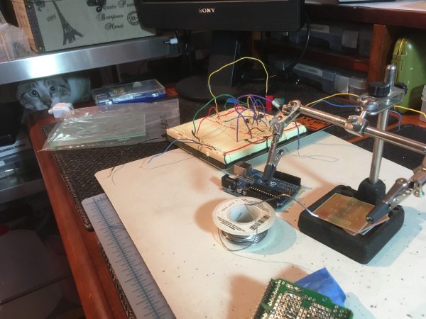
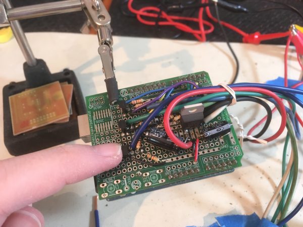
With a working prototype on the breadboard and the documentation done, it was time to solder up something for realsies. I considered etching a custom board, but that would have taken more time than I had. I also considered using protoboard, but that would require fussy interfacing with the Arduino. In the end, I decided the easiest was to tear down the old circuit and reuse the Adafruit protoshield. It’s a nice board and handles all the Arduino goo very nicely.
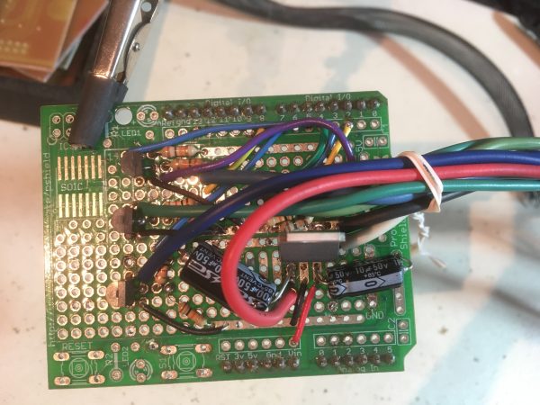
As I was building this, I noticed something interesting. The direction-control relays are both always in the same state. They are both idle, or both energized. That means I was able to simplify the circuit, eliminate a driver transistor, simplify the code, and save a pin on the Arduino. Huzzah! The board you see above is the simplified version with only two driver transistors (the third is the aforementioned brake light input).
With the board soldered up, I hooked up all my relays, and set up another test. This was just a formality, since I knew the circuit worked, so I blithely turned on the power, yawned, checked my watch, played with the cat, and promptly blew one of my transistors. Hmmm.
Did you catch what I did? I simplified the circuit by combining the control of the directional relay coils. However, recall that one coil is drawing around 150mA, and my transistors can only handle 200mA. I just hung two coils off one transistor, thus drawing 300mA and making an adorable little toaster oven.
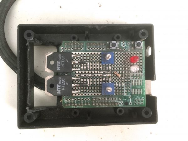
What to do now? I don’t have any beefier transistors on hand. However, you may have noticed something in the photos of the broken device that I initially received. It had two very hefty transistors on it which I cut off the board and tossed in my haste to clean up the PCB for reuse.
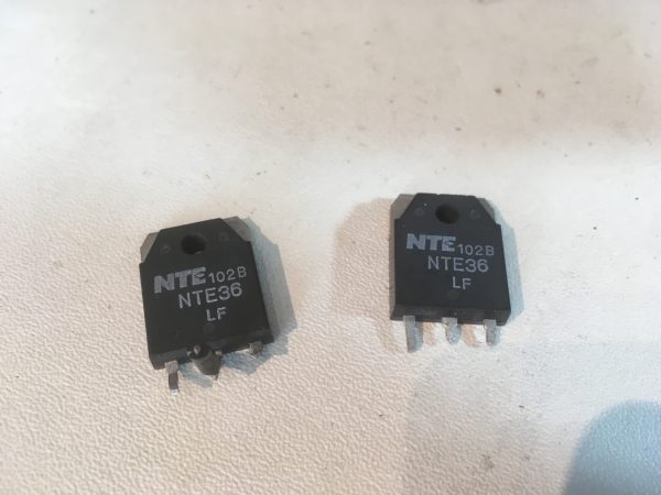
Those monsters are 160V 15A power transistors. Those are some serious NPN junctions right there. I could drive…. mathmathmath… two-hundred-thousand relay coils with one of those. Or thereabouts. I only need to drive two, so this is killing a fly with a Buick strapped to a nuclear bomb, but the price is right!
Of course, the pin-out on these transistors doesn’t match the 2N3904. That would be too easy. In fact, the pins are shuffled in exactly such a way that all the connections have to cross no matter how you arrange it. Because screw you, that’s why. I ended up bolting it flat on the board and rejiggering my circuit a bit to route everything nicely.
Needless to say, this new transistor doesn’t even blink at driving two coils. Result!
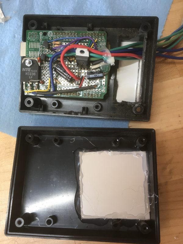
The final step is to clean up the enclosure. The original one is clearly a repurposed…something from… somewhere. It has a lot of holes to intake dirt as efficiently as possible, and no strain relief for the wiring. I added mechanical anchoring to the external harness with some zipties and hot glue. To patch the holes, the junk pile coughed up a sheet of ABS plastic, and more hot glue did the trick there.
Unfortunately, there’s no happy ending here with exciting video showing this thing in action. This is Reality Blogging, and real life doesn’t generally tie itself up in the nice narrative bow that we would like. The fact is that the Big Fish car has been grounded for the foreseeable future due to circumstances beyond anyone’s control. It’s a bummer, but the people involved will be back to racing some day. Maybe then this little box will get its chance to shine. If so, I’ll be sure and post an update here on Blondihacks.

Totally reminds me of this episode of daily transmission: https://youtu.be/QMoQ16sJRtc Putting some serious engineering into a
…Car of questionable quality. (sorry, accidentally tapped submit)
Those guys are in fact Lemons racers. Know ’em well!
Great read Quinn!
Thanks! 😀
Will the components be OK just soldered down, nothing that will come off because of vibrations etc? Anyway nice job, I always find it interesting to see how people solve problems under some kinds of constraints.
Great question! That’s definitely always a concern in automotive applications. One way to be sure about that is to pot the whole thing in epoxy. That makes it forever impossible to repair or modify though, so not a great option for an amateur racing team. More and more commercial car electronics are done this way, though.
Another good option is to simply cushion the control box with some rubber bushings when attaching it to the car. That will take care of 99% of problems that might arise from physical forces, assuming the wires are also secured. Securing the wiring is the most important thing in car electrical. Making sure nothing can move, and nothing is touching any abrasive edges. The automotive relays themselves can be mounted directly to the car- they’re made to take abuse.
Filling the container with sprayed/sheet foam or sponge would be a good idea too as long as it doesn’t heat up that much.
“…killing a fly…” I just about died reading that line. If you’re not doing improv on the side… you really should be. Seriously.
makes me wonder if the original designer of the whole system (mechanical parts too), put any consideration for optimal zero lift angle of attack. of if they selected a laminar flow airfoil design. these things supposidly have a ‘drag bucket’ where they experience less than normal drag for a narrow range of aoa angles. aircraft are designed to cruise with the wings at those angles to save fuel. anyway stuff i learned while learning the math needed for writing a crappy aerodynamic flight mod for an old space sim in the days before kerbal space program.
for racing applications i think it would be beneficial to keep the airfoil at the lowest possible drag configuration at all times when its not needed for downforce. to come up with calibration data, run the airfoil on cruise control and use load cells to measure both lift and drag forces. the current aoa of the airfoil can be measured with a potentiometer, and the speedometer value off the can bus. logging them with your dev board of choice. have the driver hold a constant speed while sweeping the airfoil across its range of motion. should be enough data to generate a pair of look up tables (one for min drag and another for max downforce modes) that you can cram into your mcu’s diminutive eeprom. a little interpolation and you can find the optimal airfoil configuration for the situation. maybe even take it a step further with a gyro to compensate for pitching motions caused by the suspension and varying torque.