Wherein we ensure I never have to hear my own thoughts.
I’m a podcast junkie. That might be entirely literal, given that I can’t seem to go more than a minute with just the voices in my head to listen to. The moment I have a chore of more than 10 seconds to perform, I inevitably fire up some podcasts to occupy my brain. This includes showering, and to that end one of my favorite devices is my bluetooth shower speaker. I’ve made heavy use of it for a couple of years, but it has stopped functioning. For what these things cost, two years is probably about right life-span-wise, but on the other hand, there really shouldn’t be much to go wrong with it. There are no moving parts, no high voltages or thermal stresses, and at no point has the cat played with it. All of this adds up to, “it’s time to take it apart and determine how it could have possibly stopped working”.
The one symptom that I noticed is that, if I plugged it into its charger over night, it would work again for about 30 seconds. This strongly suggested the battery had gone bad. Perhaps we can replace it? There’s only one way to find out. If nothing else, commodity consumer products like this always have a lot to teach us about design-for-cost and design-for-manufacture.
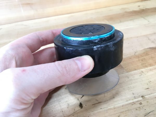
The first challenge is, of course, how to get into this thing. As my regular readers know, I will always say, “if it was assembled, it can be disassembled”. Whether it fully survives the process is a different question, but one way or another it is coming apart. The one thing that can defeat this mantra is sonic welding. That would require cutting to separate the parts. However, sonic welding is, in my humble experience, not common at all in consumer products. The only place I have ever encountered it was on an Apple power adapter. Even glue is not that common, though even that is easily defeated with a little heat. No glue made survives heat for long.
The first thing to look for is screws, or screw-shaped areas. Under rubber feet is very common, or sometimes they will be behind plastic plugs as we saw with the salad spinner. This speaker had plastic plugs very much like that spinner, so that’s the place to start- by drilling out those plugs.
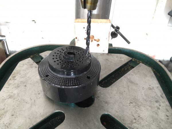
Much to my surprise, the plugs were not plastic, but rather some kind of goo. They looked like plastic, but gummed up on the drill bit. They didn’t mold-in the screws after all, they just sealed them with something like silicone (although it’s not silicone- probably something cheaper).
Once I realized this, I grabbed a pick and cleaned out the remaining holes with that. The drill press made pouty faces at me for the rest of the day because I got it all dressed up for nothing.
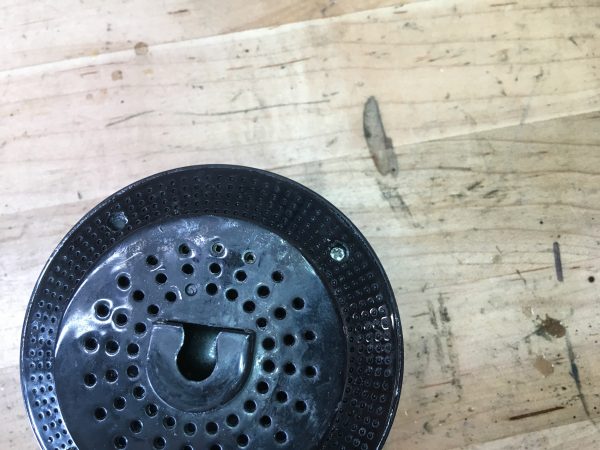
Even with the screws removed, it wasn’t clear how this thing came apart. It still seemed pretty buttoned up.
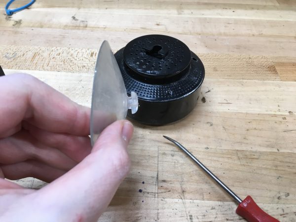
Since this thing is designed to operate in a shower, it must be water-sealed somehow. I half expected to find a gasket around the seam where it comes apart, but in fact their solution was simpler. They had simply coated the joint in some sort of cheap sealant, which is what was still holding the device in one piece. A little love-twist with some channel lock pliers broke it loose, and we were in like Flynn (with apologies to Dave Jones).
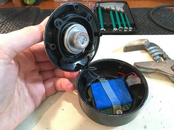
The speaker is a rubber cone type sealed against the top of the enclosure, and the bottom contains a PCB with a lithium battery on top. The charging port is made water tight by what appears to be hot glue, but it is probably some sort of silastic or epoxy. It’s crude, but seems effective, so I won’t be touching that.
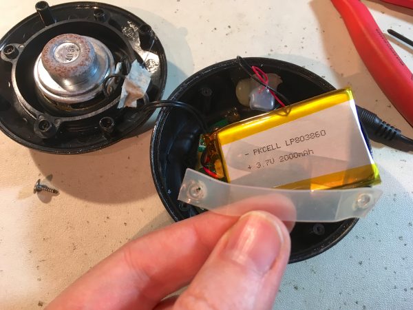
Now then, the battery is our suspect, so let’s get that thing out of there.
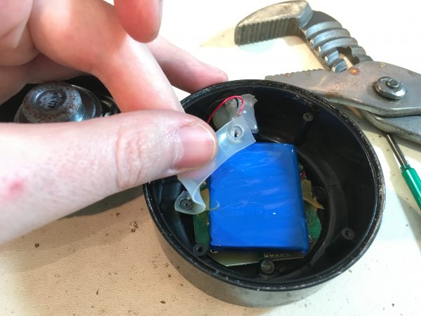
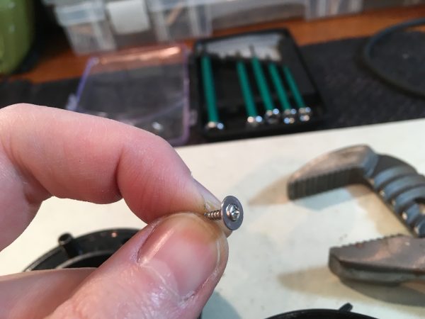
With that hefty strap removed, the battery should lift right out, yes? Surprisingly, it didn’t. It was extremely uninclined to move, despite having no apparent hold-down.
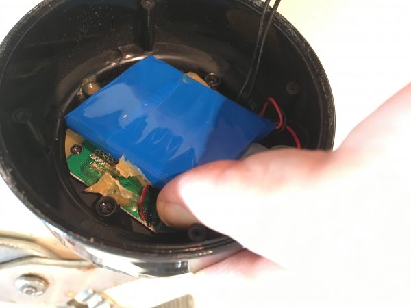
It took some non-trivial effort to unglue that battery from the PCB. I had to pick at it with a razor blade while applying upward pressure on the battery. The silastic would not release or tear. It was so impressively glued down that I really question the need for the mechanical strap. A fail-safe to be sure, but given the price point of this device, it’s a surprising choice to have redundant methods of affixing the battery.
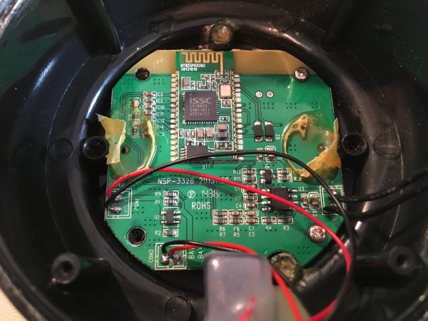
The PCB has some interesting design details. You can see they’ve used an off-the-shelf bluetooth module with a PCB antenna built in. These often have the problem that the ground plane on the PCB you attach them to will block the signal. Common solutions to this include hanging the Bluetooth module off the edge of the main PCB (which complicates enclosure design) or cutting a notch in the main PCB (which makes the PCB more expensive). Here, they have managed to not have any copper in that region while still maintaining the full size and shape of the main PCB for low cost and easy physical installation in the case. The area around the antenna doesn’t even have silkscreening or solder mask on it, so I wonder if the board is shifted up one centimeter during the entire production process so that no steps affect that area? I’d like to see how that was done. It’s a nice solution to the problem of using bluetooth modules without obscuring the antenna.
I also find it interesting that the bluetooth module is unshielded. A common reason to use these modules is that they are pre-approved by the FCC in the US. Getting FCC approval for a product that intentionally produces radio waves is an expensive and lengthy process, but as long as you use a pre-approved module unmodified, you can skip that step. However, these modules are usually RF-shielded (except for the antenna area) to maintain FCC pre-approval and make tampering evident. This device is naked, which suggests that its use here is more about getting a cheap commodity module that solves the bluetooth part of their design. The packaging on the device claims FCC approval, but the markings may well be counterfeit. This is often the case with other regulatory agencies like Underwriter Laboratories (UL), CSA Group, or others. If a suspiciously-inexpensive imported product has an alphabet soup of regulatory approvals slathered all over the packaging, it’s a safe bet they’re all fake. Nobody is going to kick in their door in China for putting the UL logo on their box, so they do it to increase the appearance of legitimacy.
Anyways, back to our PCB. Another design feature that is worth noting are the regular grid patterns of tiny vias. These are often used as a budget form of thermal management (effectively making the ground plane into a heat sink) but this circuit shouldn’t have much demand heat-wise. In this case, I suspect it is “via stitching”, a technique used to tie PCB planes tightly together electrically, reducing impedance and shortening return loops. Rows of tiny vias are also used to reduce cross-talk in RF circuits (called “via shielding”), but for those I would expect to see them following alongside vulnerable traces. These are regular grids, which is indicative of stitching and/or heat sinking. Via stitching/shielding is something you never saw on PCBs a few years ago, but now every consumer product is using the technique. It’s interesting to see high-end electrical engineering techniques trickle their way down to cheap products as time passes.
Overall the quality of this board is very good. It’s all machine pick-and-placed and reflow-soldered. There’s no evidence of bodging or child-labor-at-gun-point-hand-soldering (as I’ve seen in some other recent disassemblies). The through-hole power wires are hand-soldered, probably as the final step in the production line, but the quality is fine.
Let’s look at the back side of this board now.
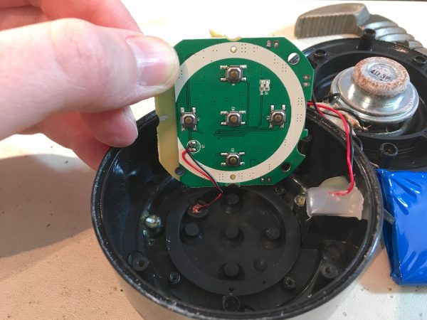
The LED is glued into a hole in the rubber membrane and wired to the PCB, so this is a possible ingress point for moisture. If that LED isn’t perfectly sealed, or if the glue cracks over time due to flexing of the one-piece control panel membrane, things could easily get wet in there. However this device is not rated for full immersion, so this is probably fine.
Okay, so enough snooping. Let’s turn our attention to the problem at hand. Why doesn’t it work? Due to the works-for-a-few-seconds-after-charging symptom, I suspected the battery. Let’s take a look at it.
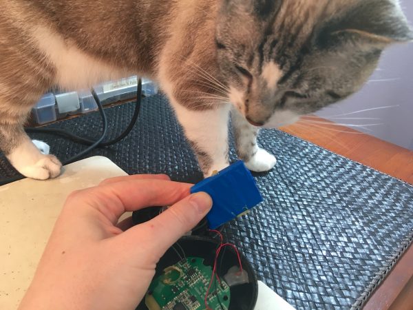
It seemed that either the battery isn’t getting a charge, or it isn’t taking it. Let’s see if we can distinguish between those cases.
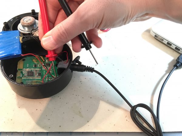
With the charger plugged in, I read ~4V on the battery pins. That suggests the charging circuit is okay, and it’s certainly trying to charge the battery. However, with the charger unplugged (now reading battery voltage only), the voltage drops to ~0.5V. The charger was plugged in over night, so the battery should be charged. With the charger unplugged, I would expect the voltage on the pins to drop a little below charging voltage, but not far for a fully charged battery. Thus it would seem the battery is not taking the charge.
The battery looks to be of good quality. It’s Samsung branded, and looks perfectly robust for the application. My guess is it’s just worn out. It could be that the speaker’s charging circuit is primitive, shortening battery life. Lithium chemistries are very fussy things. The battery is ~3 years old, and gets used up and charged again about once a week. I’d expect to get more cycles than that out of it, but these things do wear out.
A reasonable thing to try at this point is replacing the battery. My first stop for such things is Adafruit. Full disclosure: Limor Fried is a Patron of this blog, but I shopped there long before that happened. They have great stuff and the world needs more women-owned businesses, so go give them your money.
But wait- there is now a cool opportunity here to improve this device. There’s quite a bit of internal space, so I should be able to put a larger battery in there and get more life between charges! Of course I had to try that. I measured the space and sifted through specs until I found the largest battery that would fit.
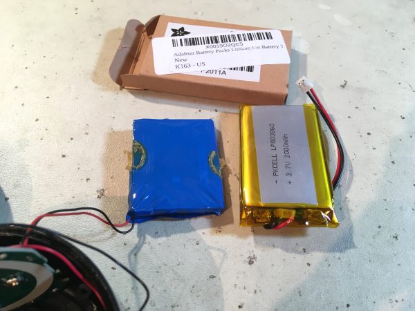
My Hakko 808 desoldering gun made short work of removing the old battery. I didn’t have a connector that would fit in the tiny space on the PCB allocated to the power connection, so I cut the connector off the Adafruit battery and soldered the wires into place. This is better anyway, since a mechanical connector would be vulnerable to corrosion if moisture is getting in there (as the speaker body suggested).
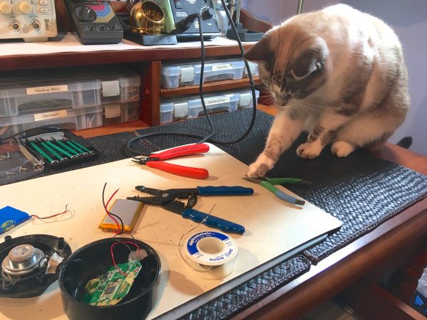
With the new battery installed, it was time for a little test.
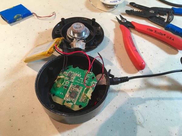
Okay, time for some reassembly!
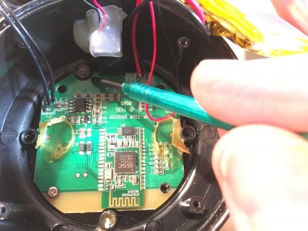
There’s a nice design-for-manufacture aspect here that I noticed on reassembly. The PCB only goes into the enclosure one way because of a series of asymmetrical notches and posts. This is smart, because while it costs virtually nothing at the design stage to do this, it no doubt saves immense time and prevents mistakes on the production line. If your thing only goes together one way, tired underpaid workers won’t get it wrong and lower your yield. It also prevents returns and customer support issues for retailers who might otherwise have to field calls about the Play button being Fast Forward because the PCB was rotated 90º in their enclosure. Good design is about a lot of things- it affects costs all the way up and down the production and usage life cycle of a product.
Okay, back to reassembly. At this point I ran into a small snag. Remember how I admired the silicone strap retaining the factory battery? Remember how I then crowed about making the battery larger? You see where this is going.
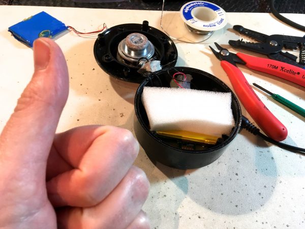
My solution? Foam rubber. This speaker spends its life sitting on a shelf in my shower. The battery does not need mil-spec physical restraint in the enclosure.
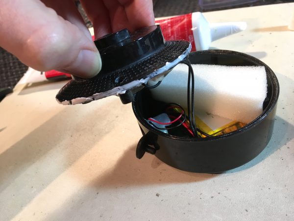
The final trick to reassembly is recreating the water seal that existed before I got in here with a drill press and channel lock pliers (wasn’t that fun, though?).
Luckily, deep in my junk pile, there was to be found… half a tube of bathroom silicone. Just the thing.
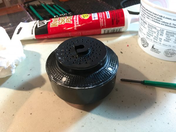
With everything reassembled, I charged the new battery and I’m pleased to say it works very well now. Yet another piece of engineered-to-be-disposable commodity consumer gadgetry saved from the landfill because of a perfectly repairable failure mode.
Excellent and well-documented work.
I bought my wife a nearly identical one for $5, which died in a month with a badly swelled cell. Unlike yours, the main board had no cell protection, only a single diode and current-limiting resistor between USB5V and the cell. Since the cell had no protection board either, it was definitely being overcharged. I replaced the cell with one scavenged from another cheap dead BT speaker, this one with an included charge/discharge protection board. After verifying that it cut off charging at 4.2V, I did a very similar caulking job on re-assembly and it’s worked well since. Here’s hoping we get a few years out of it.
While doing surgery I also desoldered the microphone and caulked its hole shut, since neither of us has any interest in using the phone during a shower. 🙂 One less moisture ingress point.
Sounds like an even better repair than mine! Nice work!
I can think of several ridiculously low priced gadgets that I’ve repaired in a similar fashion. A few of the repairs cost more than what was paid for the item in the first place, but satisfaction of a job done has got to be worth something, right?
I think most of my repairs cost more than the item is worth, but as you say, it feels good! Also, something deep inside me just can’t abide throwing things away if they can be fixed, no matter how inexpensive they are.
You sure that was “in like Flynn”?
I’da called it “in like Quinn”.
Oh my god, I can’t believe I missed that gag. I am definitely stealing that for future use. 😀
You’re welcome
😛
Your note about the RF shielding on Bluetooth module made me think because I’ve only seen unshielded Bluetooth modules. It turns out that I must only buy gadgets in the same price bracket as this speaker. Most of the Bluetooth modules on Digikey have RF shielding. Interesting.