Attempting to determine why it sucks so very much.
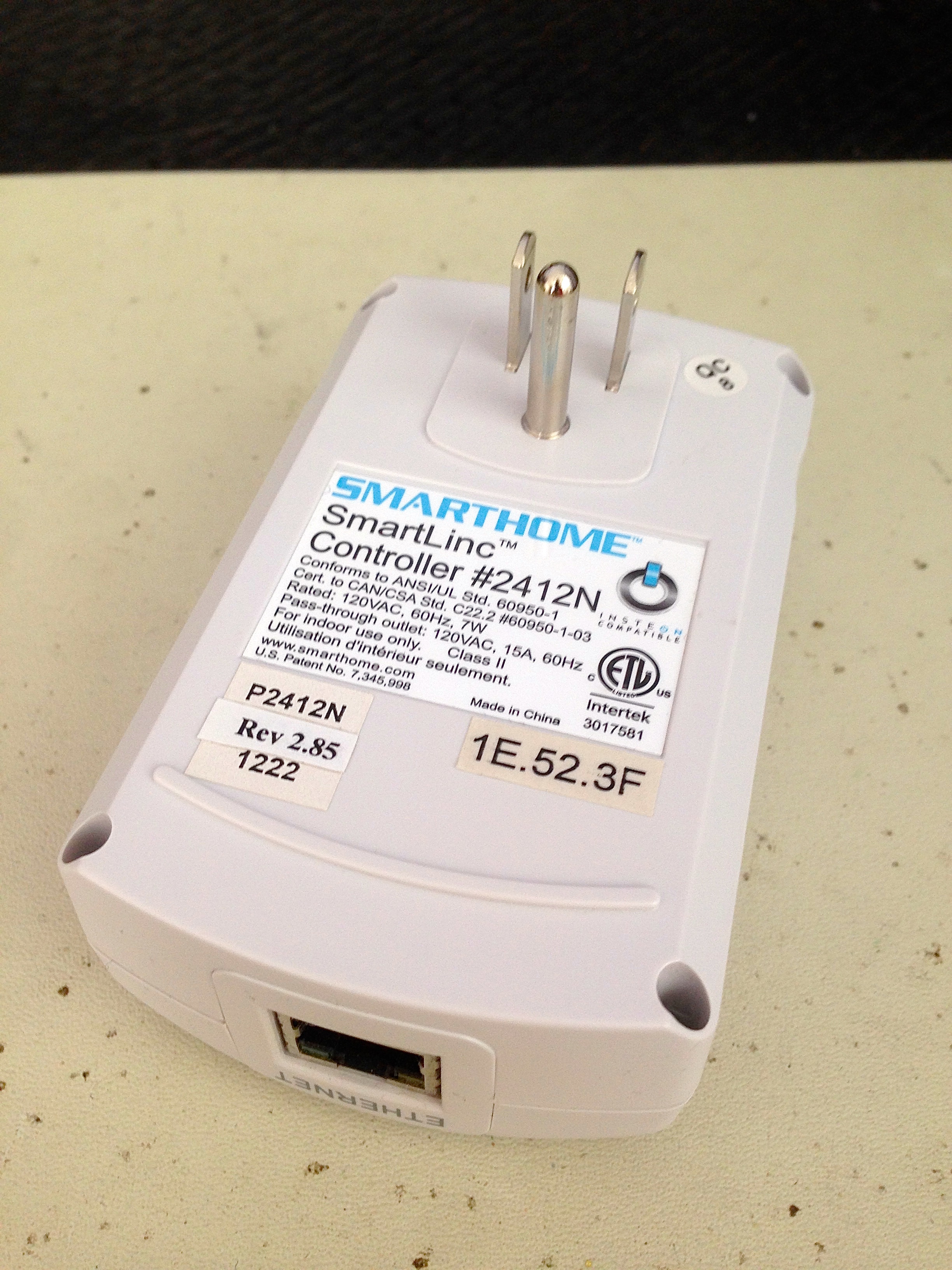
Like many hackers and tinkerers, home automation is a subject of irrational fascination for me. When I bought my house, I started making plans for an elaborate home-brew automation system. However, I quickly realized that the amount of effort involved far exceeded what I was interested in investing, and the end-result would be less feature-rich than what you can buy for reasonable cash money. Furthermore, many friends and colleagues swore by the Insteon system for this purpose. Insteon is a home automation system (I hesitate to use the word “standard”) for which various companies make products. If you’re an average consumer, you’re likely to buy the SmartHome equipment, which works on the Insteon system. There are other commercial-grade options, but for most people, “Insteon” is fairly synonymous with “SmartHome”.
I did a basic installation in my house, using a SmartHome-branded Insteon wi-fi base station, and a couple of switches. It was difficult to set up, initially, because the software is quite awful. It also refused to work with DHCP on my home network, despite claims that it does. This required me to set up a static IP, and jump through hoops on my home network to block out that address for it. I’m not an IT expert by any stretch, so this became a tedious process of learning things about routers that I never wanted to. Furthermore, any time my home network was rebooted for any reason, there was a 50/50 chance the SmartHome unit wouldn’t reconnect properly. I had to adopt a routine of continuously rebooting things in the system in various sequences until everything started working again, then being careful not to touch it. Hardly a pleasant ownership experience, but it worked that way for about a year. Until it didn’t.
One day everything stopped working, and no amount of rebooting would help. The base station simply refused to connect to the light switches. After much googling, I determined that it was likely a phase problem. In North America, roughly half your house will be on one phase of the AC mains, and half will be on the other. Since Insteon connects primarily by sending data over the mains wiring in your house, this means that some signals are literally traveling out to the transformer in the street, and back again, to go from one outlet to another. The result is that signal interference can be introduced by things installed in your neighbours’ houses. This is likely why my system went from working fine to completely failing overnight without touching anything. A common cause of interference is fluorescent lighting systems, so perhaps a neighbour put in some CFL bulbs.
I should note that these devices are all the fancy new “dual-band” Insteon devices. These are supposed to form a mesh network in your house such that the system doesn’t rely entirely on the data travelling on the mains. I paid extra for everything to make sure it was “dual-band”. As far as I can tell, this “dual-band” system does absolutely nothing.
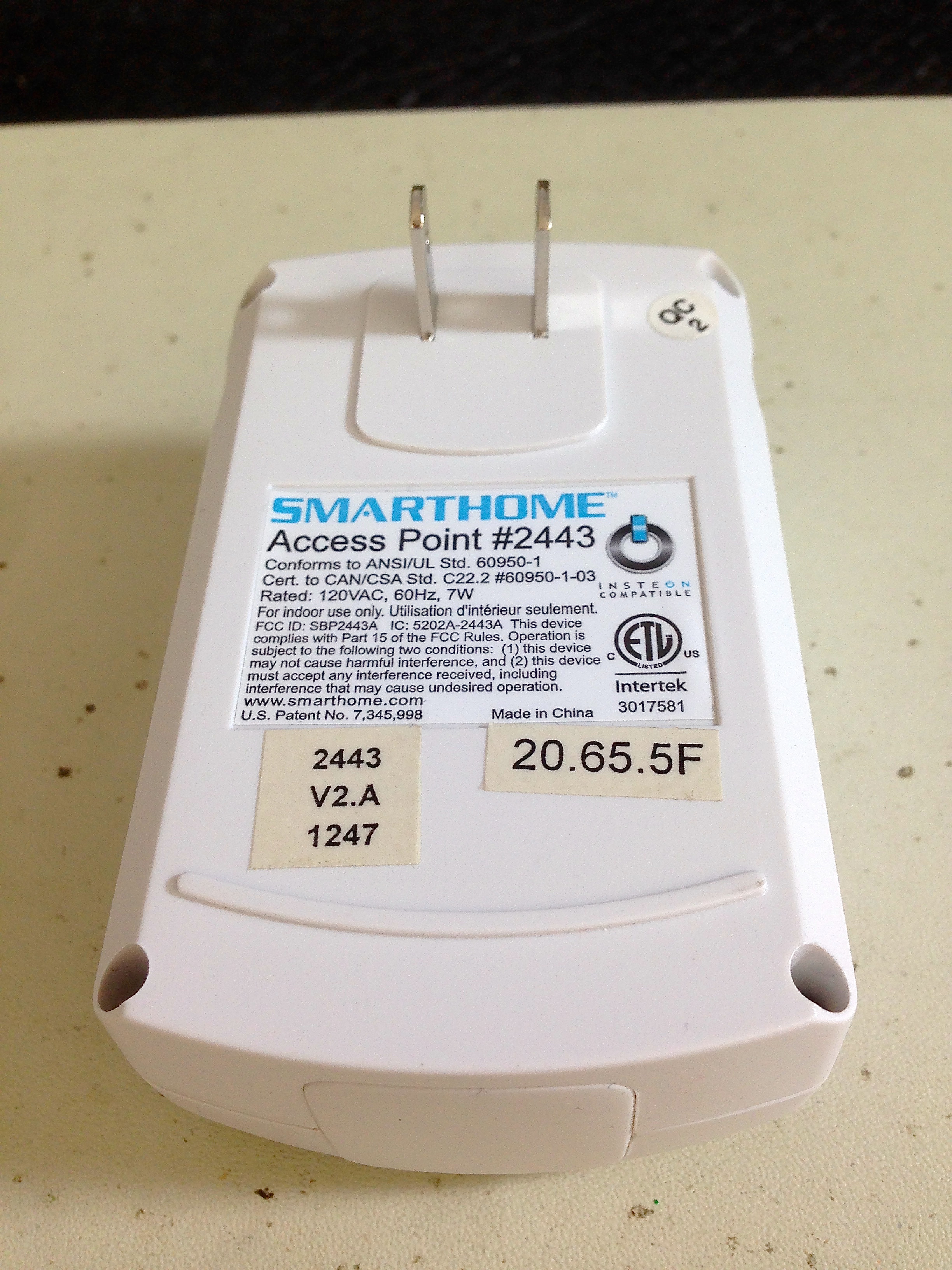
The supposed solution to my neighbour-introduced signal noise problem is a SmartHome phase bridge. This uses radio signals to repeat signals from your base station on one phase to devices on the other phase in your house without relying on data travelling down the wiring to the street and back. There’s a wacky setup process whereby you plug this device into various outlets around your house until you find one that is on the opposite phase from your base unit. I dutifully purchased a phase bridge and went through the setup process. It fixed my problem for a few months. Until it didn’t.
One day, I lost the ability to communicate with the base station. The supplied iPhone app couldn’t connect to it, and the provided web-interface would connect, but not display the (terrible) user interface. This means I lost all ability to configure the system. However, the program I had set up for my lights did still work, so I left it that way. It was frozen in time, but it worked. Until it didn’t.
After a couple months of working-but-can’t-configure-it, the base station lost the ability to talk to the switches again, and everything stopped. After a bunch more research, apparently I may new noise problems from unknown sources. The environment of my house hasn’t changed, but noise could be getting introduced on my power lines from outside the house. Apparently the solution to this is to purchase SmartHome noise filters to put on the power lines in various locations. Herein lies the problem with this SmartHome crap- the solution to every problem is always to buy more SmartHome crap. I hit my tolerance limit on that, and went back to using the light switches the old fashioned way- by pushing them with my fingers. At least the SmartHome switches still function as manual light switches when all else has failed (which it has). Very expensive manual light switches, that is.
I left things that way for a few more weeks, until one day the base station started making a high pitched squealing noise. To the best of my knowledge there was no way for this unit to intentionally make noise. This was not good. I immediately unplugged it, and swore off SmartHome forever.
That’s not enough for Blondihacks, though. Rather than tossing it, we might as well crack it open and see what we can learn.
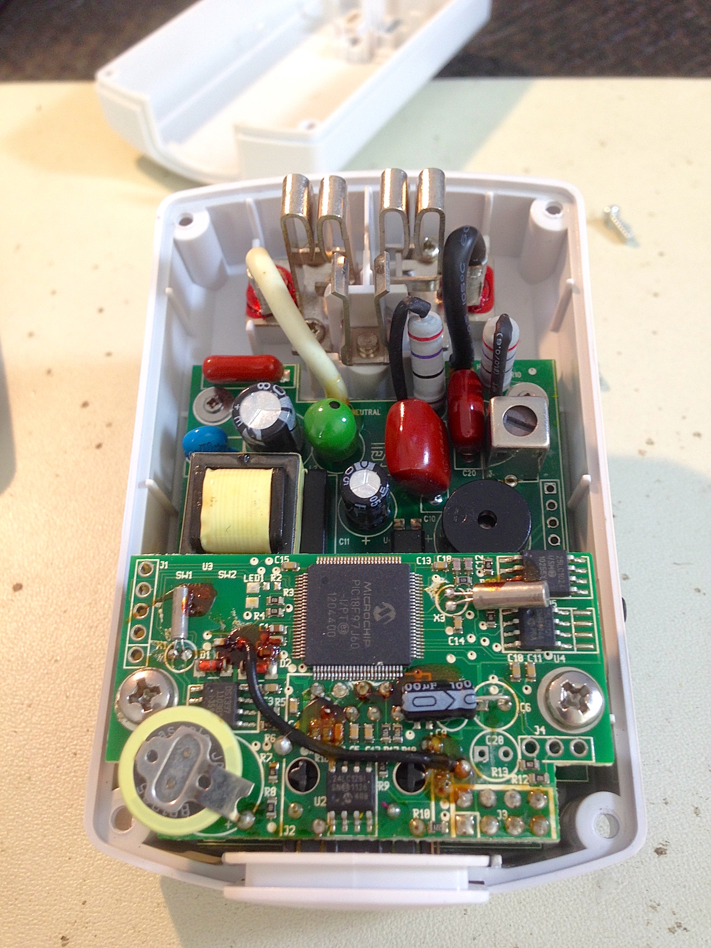
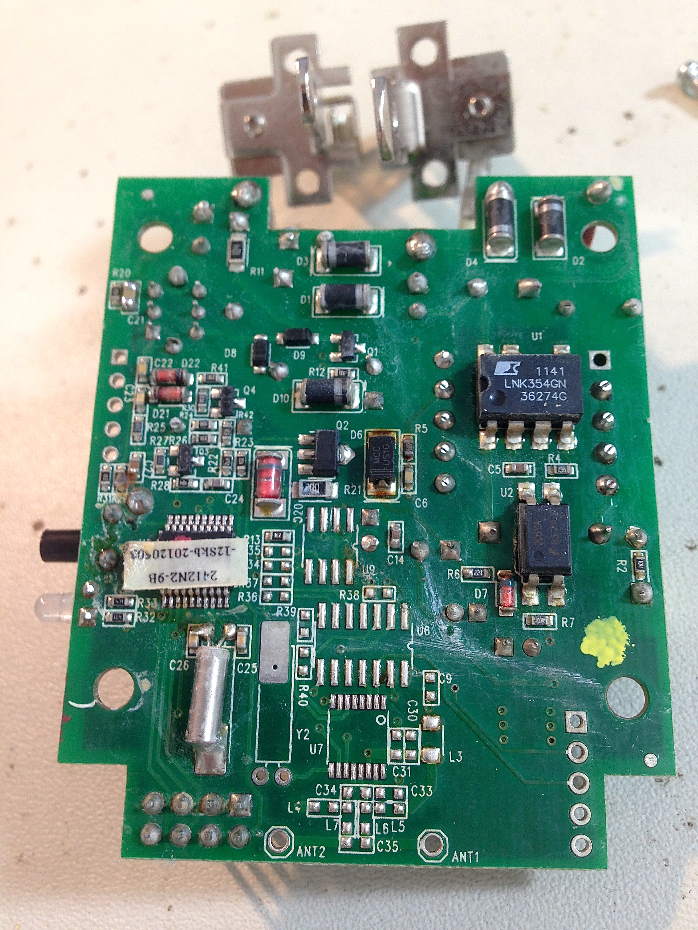
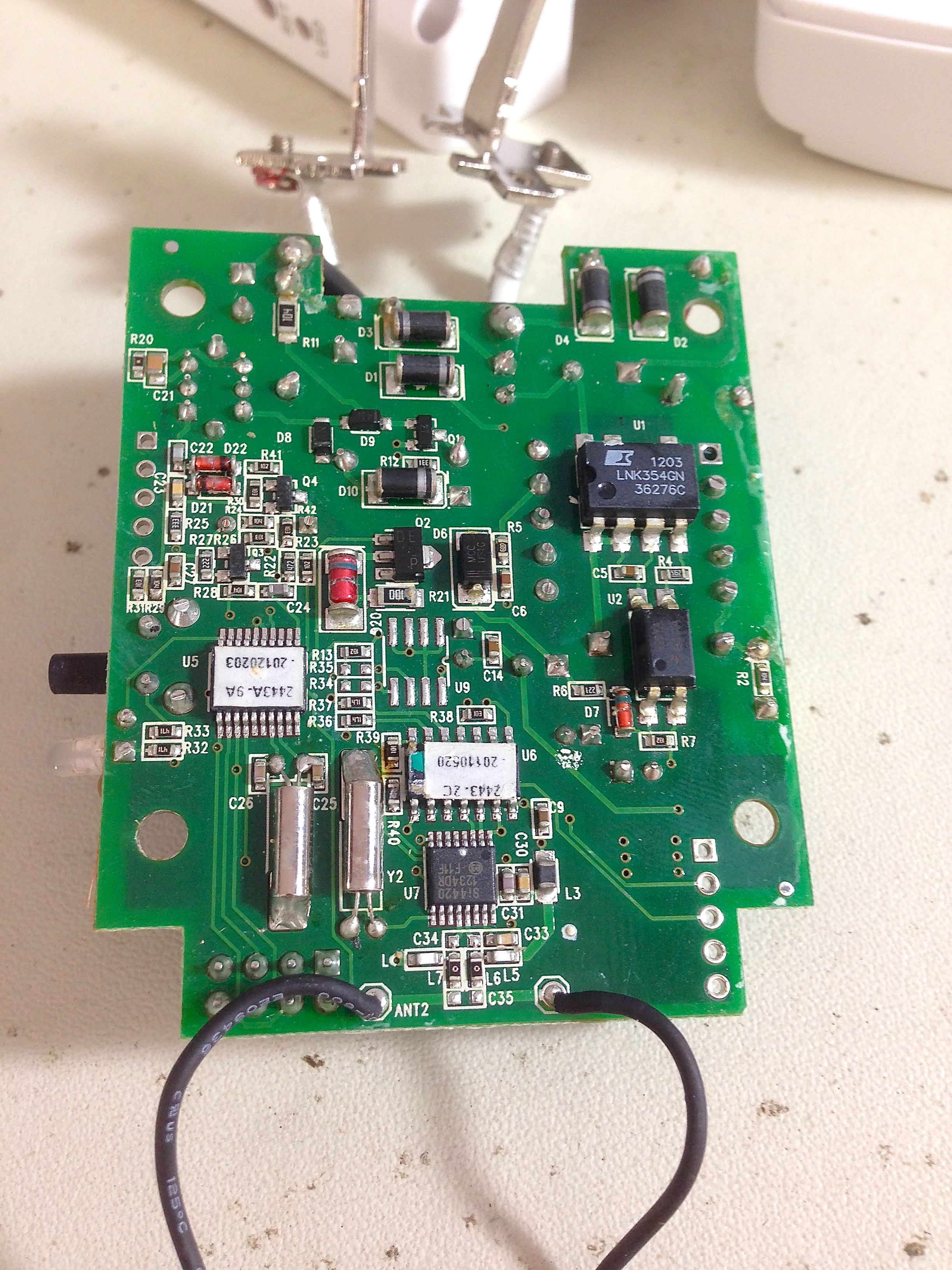
Note the unpopulated connections marked “antenna” at the bottom of this board. More on this in a second.
Now here’s something interesting. A piezo buzzer. That was most likely the source of the noise I heard. What I haven’t been able to figure out is what that buzzer is for, and why it was going off in this unit. There’s no mention in the SmartHome documentation of a buzzer, and googling has so far revealed no explanation for this. It’s clearly an alarm or warning of some sort, but beyond that I’m at a loss.

The PIC microcontroller there is what’s serving up the user interface, and doing all the actual controlling of devices in the system. The main board underneath it appears to be the signal generator for transmitting over the AC lines. This particular micro controller is actually quite a nice one. It has 128k of of flash memory, multiple UARTs, multiple timers, and a very nice ADC. Most notably, it has a built-in ethernet controller, which is no doubt the reason for it being chosen for this application.
The other interesting thing on this board is the coin cell. My guess is that it is used for storing the local networking and device configuration in RAM on the PIC, which would allow them to lock the EEPROM for security. However, than means continued operation depends on that battery, which you will note is spot-welded in place. This is a very user-hostile design, guaranteed to silently and permanently fail after some arbitrary amount of time. This battery tested a bit weak, which might be why I lost contact with the base station.
At this point, I had a decision to make. I could replace that battery, and reassemble everything to see if it fixed my problems, or I could take glee in continuing to rip this system apart and write snarky blog posts about it. I’ve chosen Option B.
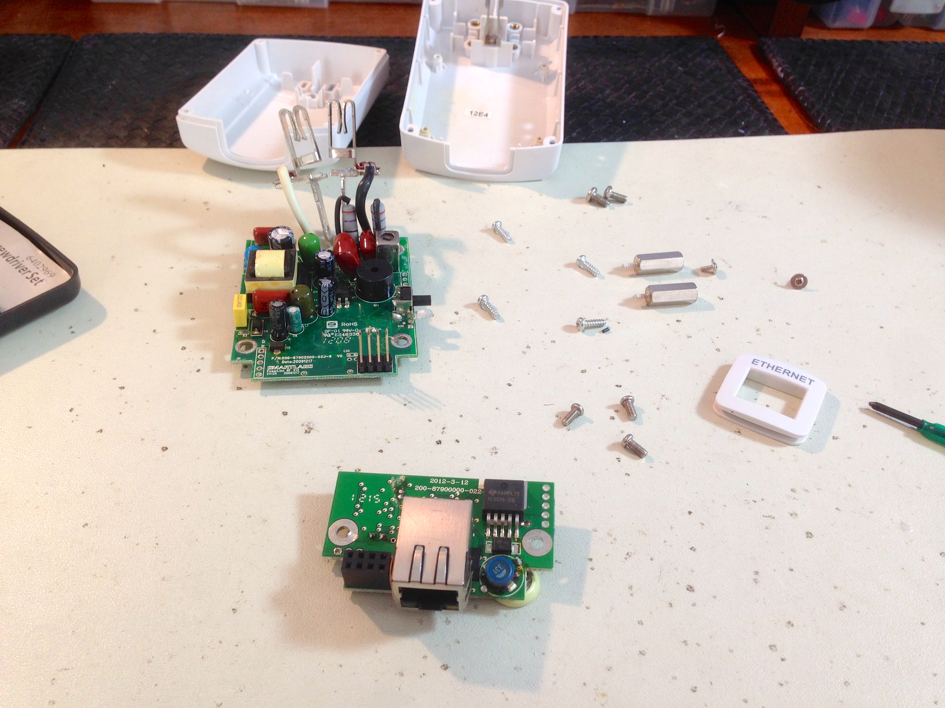
Now let’s take a look at that pseudo-magical phase-bridge unit.
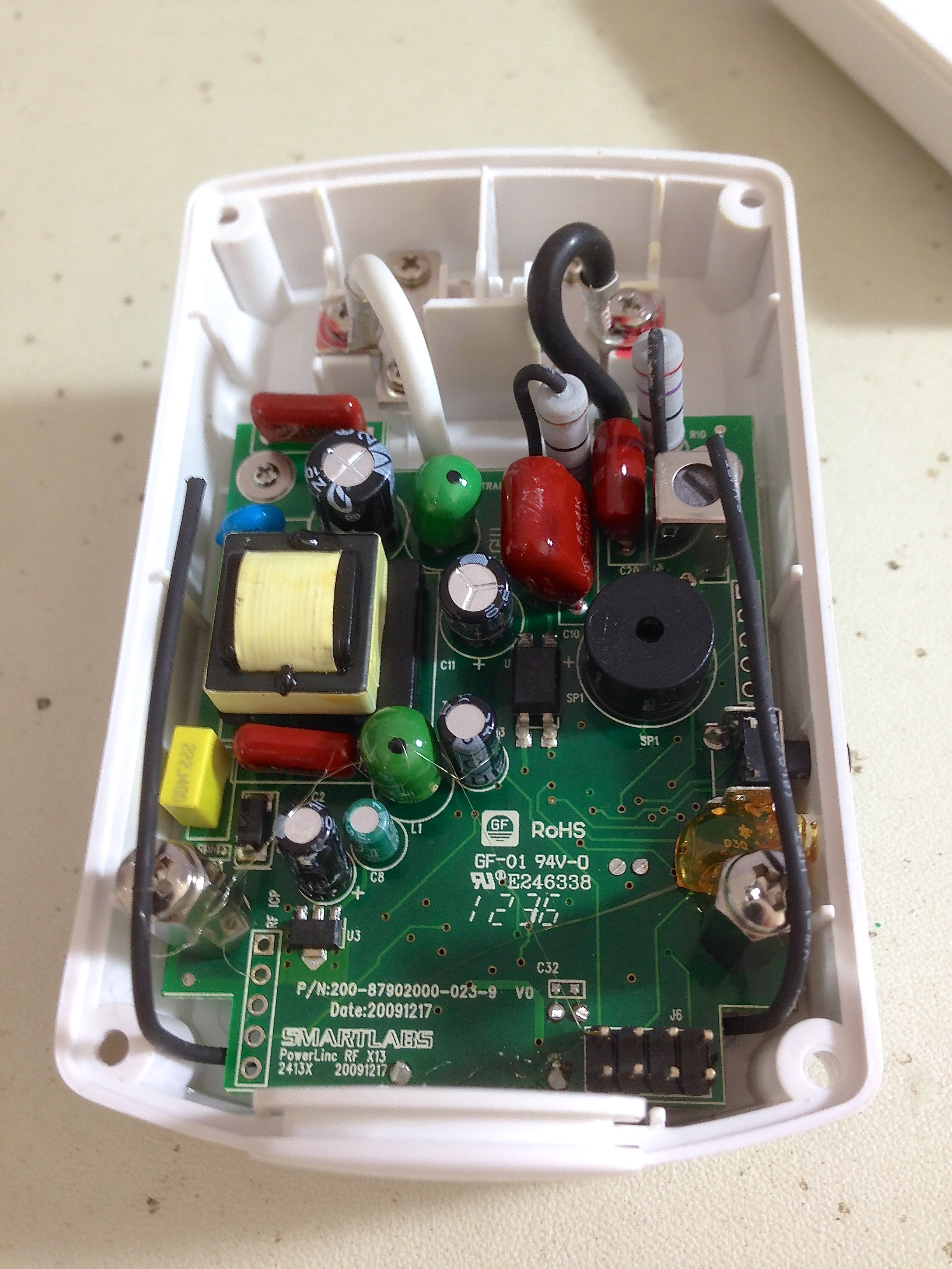
Interestingly, the phase bridge is identical to the base station, right down to the header where the ethernet daughterboard attached. It has two antennae added, which are attached to solder points that also exist on the base station. Kinda makes you wonder why they bother populating the J6 header and other parts that are only used in the base station.
That’s really all there is to these. I could break out the ‘scope at this point and start trying to figure out why they failed, but honestly that’s far more effort than these products deserve. I’ll get much more satisfaction from warming up the Hakko 808 and stripping these for parts. There’s lots of goodies on there, including connectors, switches, buzzers, LEDs, and useful passives. I’ll make the guts live on in something better.
A quick prologue- I’ve since replaced my SmartHome switches with Belkin’s WeMo products, and they are fantastic. I had them installed and running in minutes instead of hours, and the software is terrific. They are 100% wi-fi (no signal-on-mains or closed-source proprietary networks), and have so far been 100% reliable no matter what my neighbours or the power company do. On top of that, the Belkin units are cheaper than this SmartHome stuff, and no base station is required. It’s an infinitely better system, and I bid good riddance to SmartHome and Insteon once and for all.
*dusts off hands*
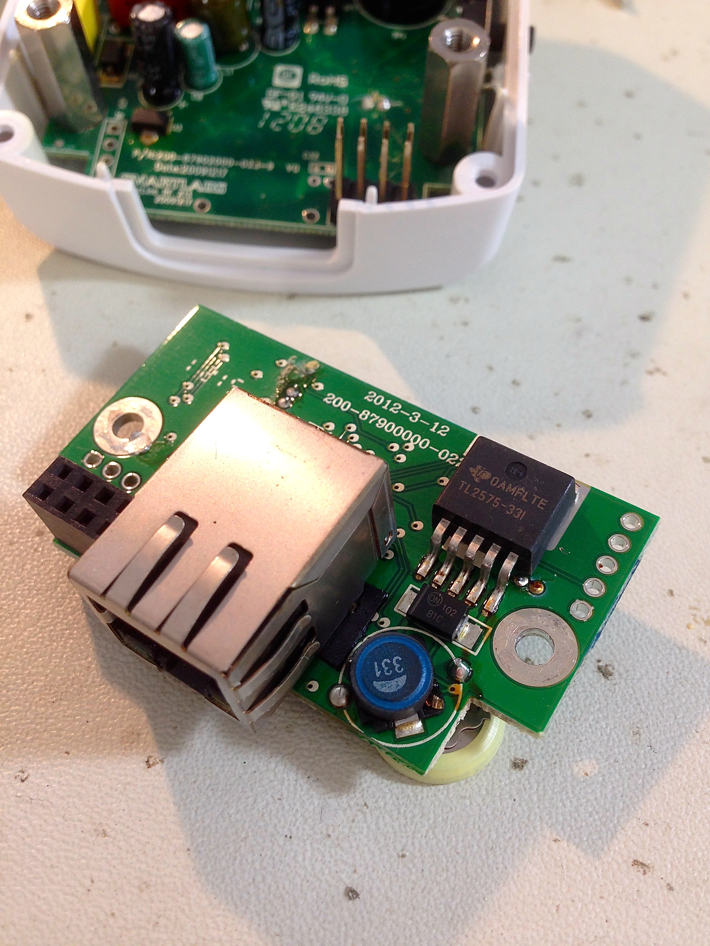
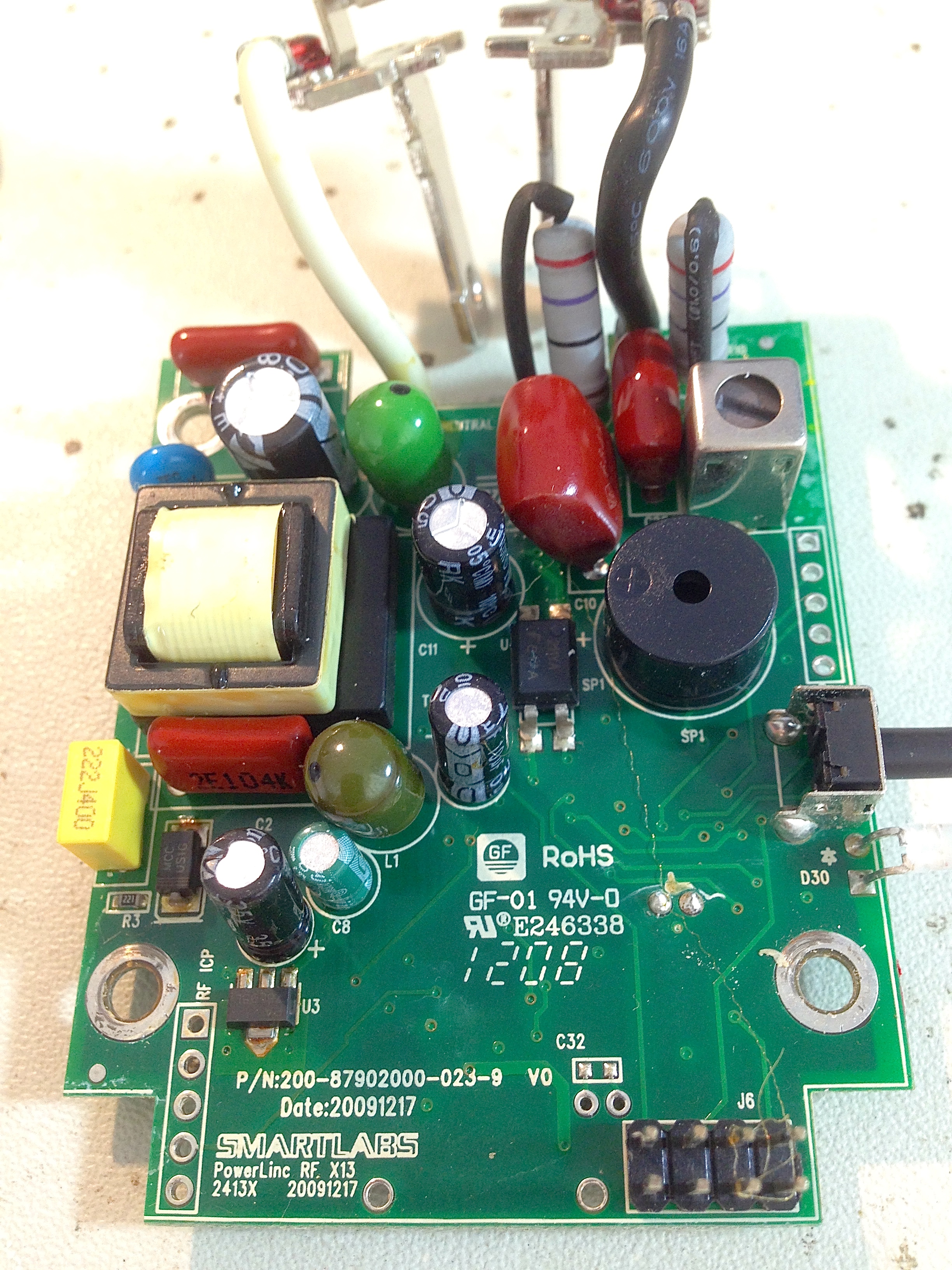
That’s not using a linear supply.
The LNK354 is an off-line switch-mode power supply. They’re really cool parts. Basically, you stick 120V or 240V in one end, and get a regulated 5V/12V/whatever out the other end with decent efficiency.
I would assume the two large “Red-Drop” capacitors are the main part of the mains-line modem thing.
Good eye! I didn’t see any switch-mode components I recognized, and the power requirements of this are low, so I assumed linear.
Incidentally, can you pull the stickers off the two small chips on the bottom of the board? Those are the interesting parts here. I’m betting one is a powerline-comm modem, and the other is probably /another/ MCU.
It’s interesting that they both apparently have their own firmware, through.
I gave it a try, but the markings underneath weren’t legible. One chip was painted over, and the other appeared to be sanded down. Seems they did not wish to be identified. Perhaps that’s the company’s IP.
It sounds like Powerline Networking is being employed here, at least for some of the units?
I’ve used Powerline Networking in a number of situations where I hoped to bridge a gap in a home where WIFI couldn’t quite reach but neither were there cable runs in the walls. Your experience is unfortunately quite similar to mine. Sometimes they’ll work for a long time and I’ll stop thinking about them…. and then they stop working. 😀 Brittle is probably a good description.
It’s been a real source of disappointment to me because there have been a few situations over the years where homeowners don’t care to open the walls and those same walls are full of 2.4ghz/5ghz squelching stuff.
If you had really wanted to replace that coin battery, could you have gotten by the spot weld somehow? I’ve always been curious how difficult it would be to get through a spot weld.
Yep, Insteon is essentially a protocol for talking to devices over a low-bandwidth network established across live power lines. A neat idea that should work great on paper, but works poorly in every real world scenario I’ve seen.
As for how to get past the spot-welded battery, I find wire-cutters work just fine. If I want that thing off, it’s coming off. 🙂
Good teardown! I’ve used the PIC18F97J60 in a couple of commercial and homebrew products (HW & FW design) and its a great chip (along with the Microchip Ethernet stack).
However, I would suggest that the coin cell is purely for holding up the DS1337 I2C Real Time Clock you can see just peeking out from underneath the coin cell. The DS1337 has no internal SRAM, so they cannot be storing any data there, and by my count I can see 3 (!?!) separate EEPROM’s on the board:
1x 24LC128 (I2C 128kbit EEPROM)
1x 25LC1024 (SPI 1024kbit EEPROM)
1x 25LC512 (SPI 512kbit EEPROM)
On the microchip TCP/IP stack the network settings are typically held in a chunk of EEPROM/FLASH below the MPFS (MicrochiP File System) that hold all the onboard webpages. In this example I’d guess all that probably lives in the 25LC1024 (its the biggest – for holding lots of webpages!). If you were interested you could dump the MPFS EEPROM with something like a bus pirate and have a poke through. There is some compression going on, but if I recall correctly anything with dynamic content cannot be compressed and should be easily viewable as standard html text.
(Who knows why they need 3 separate EEPROMs though, you’d have thought they would have just used one for everything, or two (MPFS + network settings, and everthing else).)
Another interesting place to poke at on this device would checking if they have been lazy and used the off the shelf Ethernet Bootloader on this device (like many seem to). This uses an unsecured and unauthenticated “TFTP” connection and you can potentially perform a TFTP GET to dump the firmware from the device (along with uploading new firmware 😉 ) . That would however rely on the unit working.
Looks like the little sub-board would be a pretty good Microchip Ethernet development kit all by itself!
Good catch on all those EEPROMs. I bet you’re right about that battery. I agree that Ethernet board looks like a pretty darned useful toy. Will likely try playing with that at some point. I wonder if the flash in the PIC is fuse-locked though? Only one way to find out…
I’ve not used the SmartLinc controller, but do have a fair amount of SmartHome products in use.
The PowerLinc rf board used in the SmartLinc and Access point is the same one used in many of their products. The capacitors on that board are cheap and seem to have a useful life of about 2 years (+/- a year). Once those start to go you get all kinds of flaky behavior leading up to eventual dead devices. A number of folks (me included) have have resurrected some of those devices by replacing those with better caps. In my case, none of the caps were showing the normal bloating/leaking signs of failure, but by replacing them, normal behavior was restored.
Very interesting as usual Quinn, thanks.
I’d enjoy to see a post about a recycling session with your beloved desoldering gun : what do keep, what do you throw away, how do you identify (or not) parts, how do you organize your recycled bits to be able to find them when needed, do you test the components, etc.
Not sure it’s something worth a full post in your opinion… Let us know.
Actually, that’s quite a good idea! I think I may just do that.
Thank you for breaking them open! I have loved to hate X10/Insteon products for 15 years. Same experience here, it works then it doesn’t then sometimes after a reboot it works again. Never had the courage to rip them open and investigate why. I usually swear off them for a few years, then move to a new place, and try again (maybe the mesh network will really solve it this time?) Not.
Glad WeMo is a working technology may need to investigate and replace my Insteon mess.
Ironically, I had pretty good luck with the old X10 stuff many years ago. It was slow, but seemed to work consistently. But then, it was a different house and different use case, so any number of variables could be the difference.
X10 was slow and I had trouble with bridging. Biggest problem was the neighbor across the street, who also had X10. Until we negotiated house codes we had mystery events.
I could not explain to the wife that I could control lights across the street but not across the house.
Haha, indeed. 😀