Do not go gentle into that good night.
Just when things were starting to go really well on the Put An F18A In Veronica plan, well, I fried an irreplaceable device. Yes, if you’re following along, you know that last time I somehow managed to cook the bus transceiver on the F18A, rendering the entire board unusable. I’m still not sure exactly when it happened, or what I did, but what’s important is how to move forward. A replacement F18A cannot be bought, so we must find another way. Sure, I could throw up my hands and declare defeat, but that’s not the Blondihacks way. No, the Blondihacks way is to somehow use my clumsy meathooks and 45-year-old eyes to repair this tiny device made by robots.
Now, I have some experience with soldering small surface-mount devices. I built a run of my Apple II ROM Tool, which dumps ROMs and burns EEPROMs for 1980s computers. That board used a particular Atmel microcontroller that only came in a challenging 0.5mm pitch SMT package. I needed that particular one because it has the built-in USB Host support, so that I could write a command line tool on my modern laptop to talk to it. In doing so, I got plenty of experience with the “drag soldering” method of installing these chips. Basically, you just put some solder on the iron, and drag it across the pins. The solder mostly only goes on the pins, because solder only sticks to hot metal things. You’ll get a bridge between pins here or there, but those are readily cleaned up. In general, it’s not as hard as it seems like it would be. However, in the case of building those boards, I was working with the easiest possible scenario. The PCBs were brand new ones produced by OSHPark, so they were spotlessly clean and extremely well made. The chip I was installing was inexpensive, and I had spare PCBs, so there was no pressure. If I messed one up (and I often did), I could simply toss both parts and try again. Furthermore, because it was a brand new board I was building from scratch, I could install the tricky chip first so no other components were in the way. Overall, it was tricky, but not brutal.
This repair would be a whole new level for my rookie SMD rework skills. In this case, I have an old dirty board with a ton of other parts on it. I have no idea how high quality the FR-4 (PCB substrate) is, or how good the pads are. I also pretty much only get one shot at this. Certain mistakes, such as lifting a pad or overheating other components, could be fatal. I have exactly one of this device and absolutely cannot get another one. This is a different ballgame of stakes than I have had before on SMDs!
However, that’s the completely wrong mindset with which to go into this. The way to think about it is simply, “it’s broken now so I have nothing left to lose”. That mindset makes every outcome a positive one. I’ll learn something about SMD work, I’ll get to try some new tools and techniques, I’ll level up my soldering game, and who knows- there’s a remote chance I might even fix it. If everything goes completely pear-shaped and I’m left with a device I can’t use, well guess what- that’s where I am now. With the right mindset, failure is only a lateral move. If I had figured that out in my 20s, I’d be a lot further in life right now.
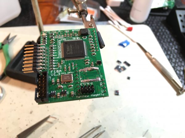
Okay kids, buckle up. I’m gonna replace the bus transceiver on my F18A.
After gathering myself into the appropriate mindset, I set about acquiring the tools to do this job. The ideal would probably be a hot air rework station and a binocular microscope, but those things are expensive and it’s not clear I can justify them for long term utility.
My main concern in this repair was removing the old device. To desolder a chip, you have to get all of its pins free of their pads at the same time. With an older through-hole chip, this is pretty easy to do with a desoldering gun. Simply sucking the solder off each pin is generally enough to loosen the chip enough for removal. Furthermore, you’re lifting the chip up, and the solder pads are under the board, so there’s minimal risk of pulling the pads off the board. Lastly, the chip itself is stronger than the solder, so if you have some straggler solder bridges, you can generally break them free. If all else fails, you can go in and cut all the pins and then soften the solder on each pin one by one to drop them out.
For surface-mount chips, all those advantages are gone. The pins are weaker than the solder holding them, so they can easily break if any force is used. The solder separation must be clean and total. The pins are too small to cut so you must somehow free all pins simultaneously. The solder pads are tiny and on the top side of the board, so if you accidentally apply any upward force, you will rip them off. That means the chip must not be pulled on at all. Finally, you have to somehow do all this with minimal heat, or you will lift the tiny solder pads off the board due to microscopic damage to the epoxy in the PCB. All of this is a tall order, and I wasn’t sure how to go about it.
However, my helpful Patrons put me on to a wonderful product designed for this purpose- Chip Quik. It’s a lot like solder (and looks like solder), but it has a very low melting point. It’s not designed to hold parts together. In fact, it dries brittle so it’s critical to remove it all before you’re done. However, it mixes with regular solder and keeps it molten for a really long time. It’s like using salt to melt ice on winter roads. By lowering the melting point of the ice, you not only make it liquid, but you keep new ice from forming in that area. This is what Chip Quik does.
To use it, you slather it on all the pins of the chip, and gradually heat it all up evenly. It melts all the solder and keeps it melted, until eventually the chip simply slides loose like magic. Then you clean up the Chip Quik and put the new chip on. Let’s get to it!
I am by no means an expert at this, but I’ll share what I’ve learned. I know that people do SMT work by hand all the time and this is hardly amazing, but for me this was a big deal. It was something I might not have thought I could do, so bear with me as I indulge in some hyperbole now and again.
There are three keys to success in this process- cleanliness, cleanliness, and cats. No, I mean cleanliness. The joke was that all three things are the same thing and that thing is cleanliness. I really like cats and got distracted for a moment there.
Our weapons in the battle for cleanliness are isopropyl alcohol and liquid flux. You pretty much can’t use too much of either. I did a whole bunch of practice with this technique by grabbing every PCB in my scrap bin that had an SMT chip on it and removing it. By doing that, I learned that pretty much all problems you encounter with this process can be solved by more flux. I was soaking the board constantly and the more I used, the better things worked.
Step one, however, is to get the surface dirt off the pins in question. This board has been sitting around for years, and it has crud on it. I went to town with isopropyl alcohol and cotton swabs until the pins on the chip to be removed were spotless and the cotton swabs came away clean.
Next, I soaked the whole area in liquid flux. I found it helpful to burn off this initial soaking with the soldering iron, then soak it some more. Burning off the flux activates the cleaning action, and applying more will get the Chip Quik to flow.
If the Chip Quik balls up or sticks to the iron but not the chip, you need more flux. Once you have enough, the Chip Quik will flow into the pins just like solder would. Move the iron around a lot and build up the heat gradually. It’s very easy to lift a pad with too much heat, and then this repair gets a hundred times harder. I had my iron set at 550°F, lower than the 650° I normally use for soldering. That helped me control the heat better. I also used the finest-point tip I could buy, because a smaller tip also helps control heat (and came in very handy later).
Practice really helps, and I’m glad I spent time pulling every surface mount device off every board in my junk pile before trying the real thing. I made mistakes and learned things with every attempt.
Once the device is removed, the next challenge is cleaning up the Chip Quik. It cools at very low temperature and the solid form is brittle, so you don’t want it mixed with your solder. It won’t do a good job of holding parts. All standard desoldering tools work perfectly well with it. I got the worst of it off with my Hakko desoldering gun, which was a big help. I did final cleanup on the pads with desoldering braid. For this step, flux is again a good idea. I soak the braid in flux, and I also apply solder to the iron on the back of the braid, so that the heat conducts from the iron into the braid efficiently. The trick with that stuff is that the braid has to melt the solder, not the iron. Also it’s critical to keep it moving or the heat will damage the epoxy in the PCB and the pads will lift off. I did this in one of my practice runs, so that was a good lesson.
Of course, you won’t get every molecule of Chip Quik off, but the pads should look clean and “tinned” when you’re done. Check for bridges, as well. You don’t want to start behind the 8-ball on solder bridges once it comes time to put the new chip on.
At this point, cleaning with isopropyl alcohol again is a very good idea. Again, you can’t clean too much. Clean, clean, clean.
If you get a bridge between two pads, a quick swipe between them with the fine-pointed soldering iron will generally take care of them. Solder doesn’t stick to PCBs, only to hot metal. All you have to do is give it somewhere better to go. That’s often safer than going in with the braid again and risking overheating the pads. Again, these pads are very small, so it doesn’t take a lot of heat to damage the epoxy in the FR-4 below them enough to lift them off.
Once the pads were as clean as I could get them without going crazy with the heat, it was time for the new part. It’s important at this point to clean up the soldering iron as well, because you don’t want the Chip Quik mixing with your solder any more than you can help it. It will weaken the normal solder. Cleaning the iron with your brass wool and re-tinning three times is said to do the trick, and that worked for me as well.
One nice thing about working with modern parts is that you can, well, just buy them. I’m used to working on retro projects and old computer hardware that rely on weird old DIP chips that haven’t been produced for 25 years. Sometimes places like Jameco carry them, but often I have to buy on eBay, wait for weeks, and cross my fingers that the chip is still working. Common TTL DIP chips can still be found new, but they tend to be a bit expensive because only hobbyists bother with them anymore. Enter the modern SMD component.
I’ll be throwing around a bunch more hyperbole now about how small this stuff is, but take it with a grain of salt. People work with SMT devices by hand all the time, and I am not special for doing so. There are entire categories of tools devoted to this area. Binocular microscopes, hot air rework stations, solder paste, stencils, etc, all exist. It’s a thing people do every day. That said, this was a very big deal for me, because I don’t have a lot of experience doing this, I don’t have any tools appropriate to doing this, and I had serious doubts in my ability to achieve this. However, I’m halfway through the job now, so it’s no time to get weak in the knees.
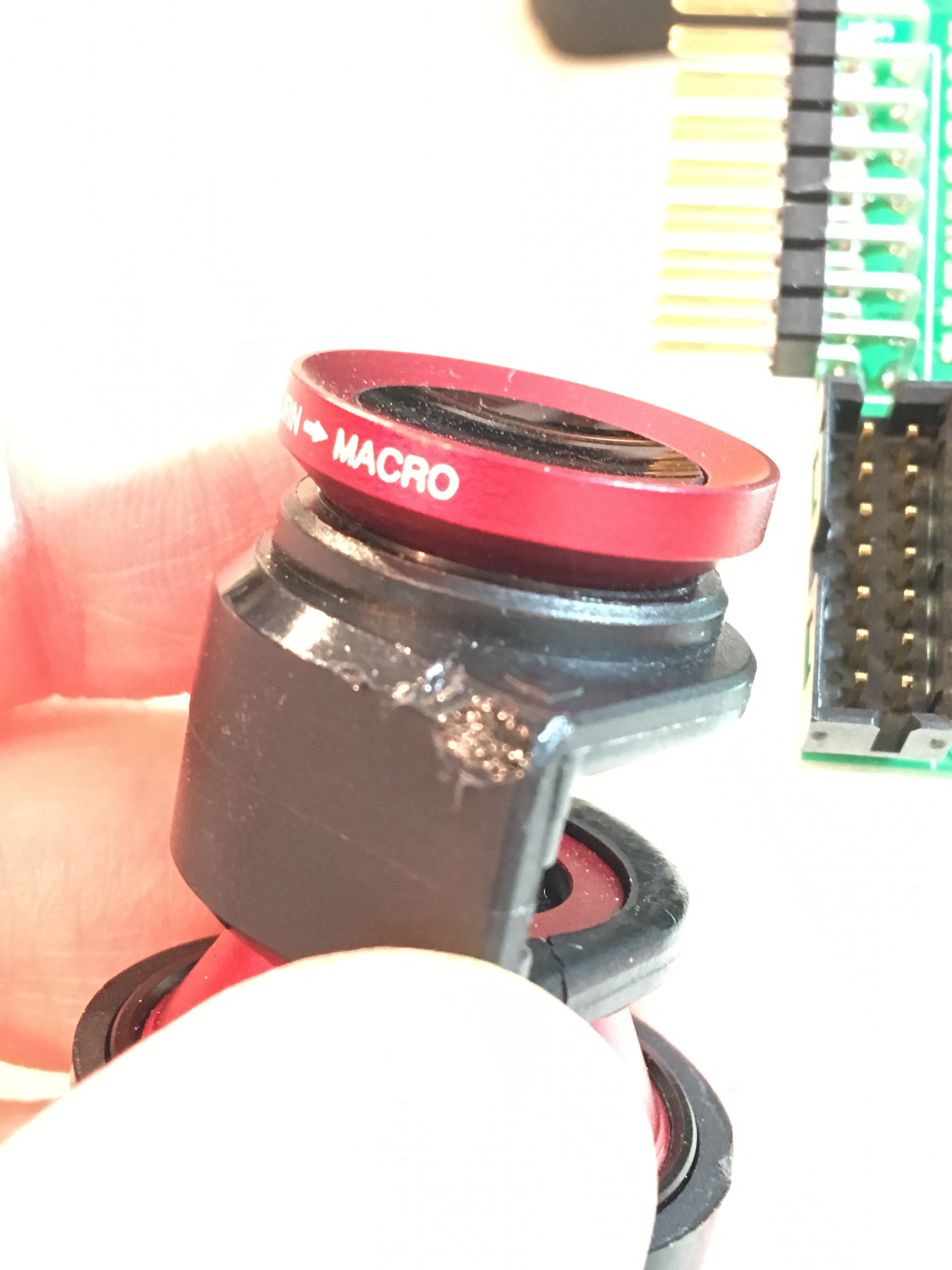
The first step for the new part is pretty easy- we need to position the chip and tack down opposite corners so it doesn’t move. Like everything else in this process, strong magnification helps a lot. My 10x head-mounted loupe was sufficient for now, but I would make heavy use of the macro lens on my camera later.
Once again, lots of flux at every point in the process helps. The funny thing about SMT work is that you basically have to unlearn all the good soldering habits you had. For example, the cardinal rule of soldering is that the work must melt the solder, not the iron. Beginners make the mistake of trying to “apply” solder with the iron like a glue stick. Well, with SMT devices, that’s actually what works the best. For tacking down the corners, what works well is putting a small blob of solder on the iron, and touching that blob to the pins you want. Holding the chip aligned with the pads while doing this can be a bit tricky, but light downward pressure on the top with tweezers seems to work well.
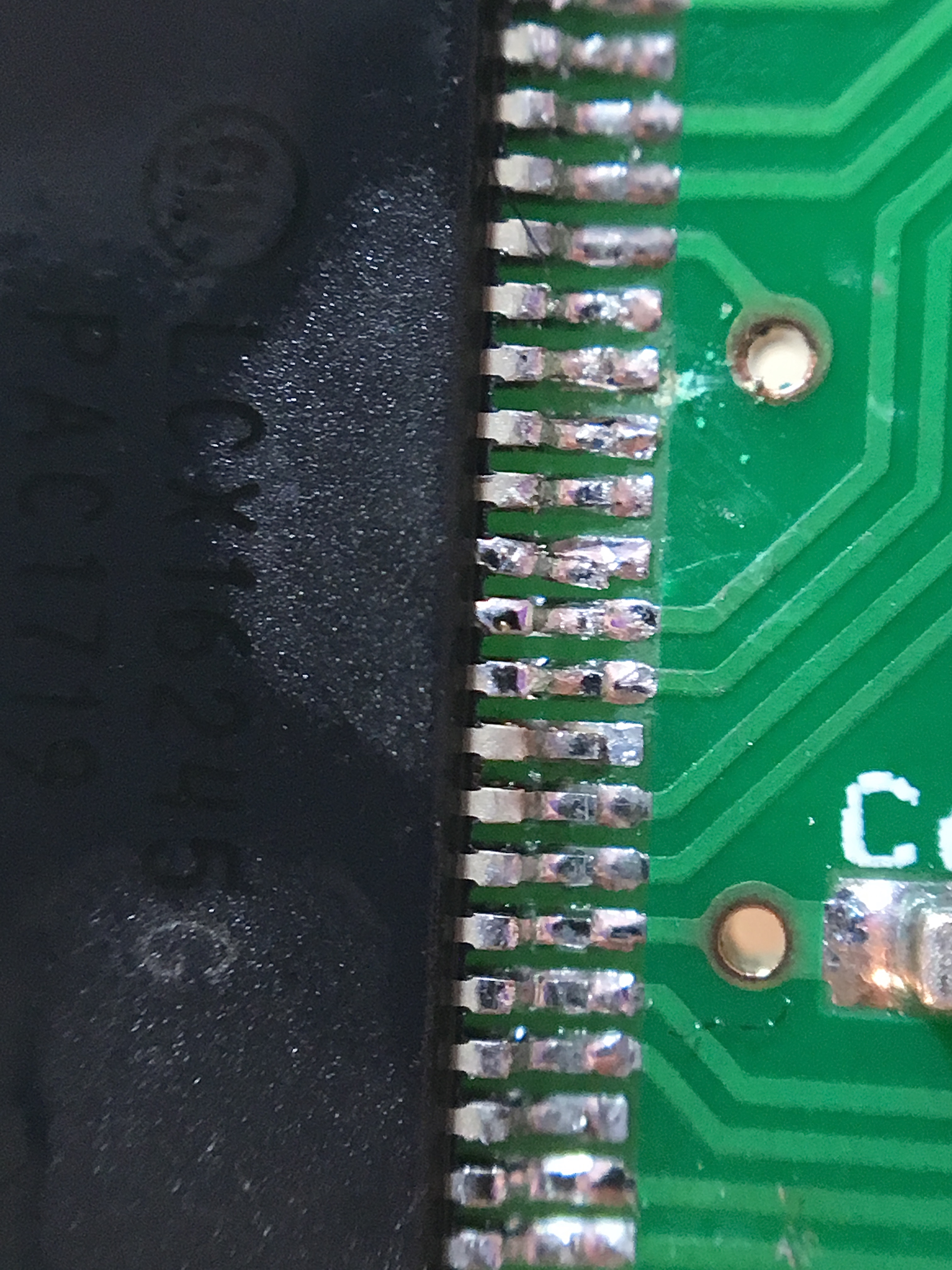
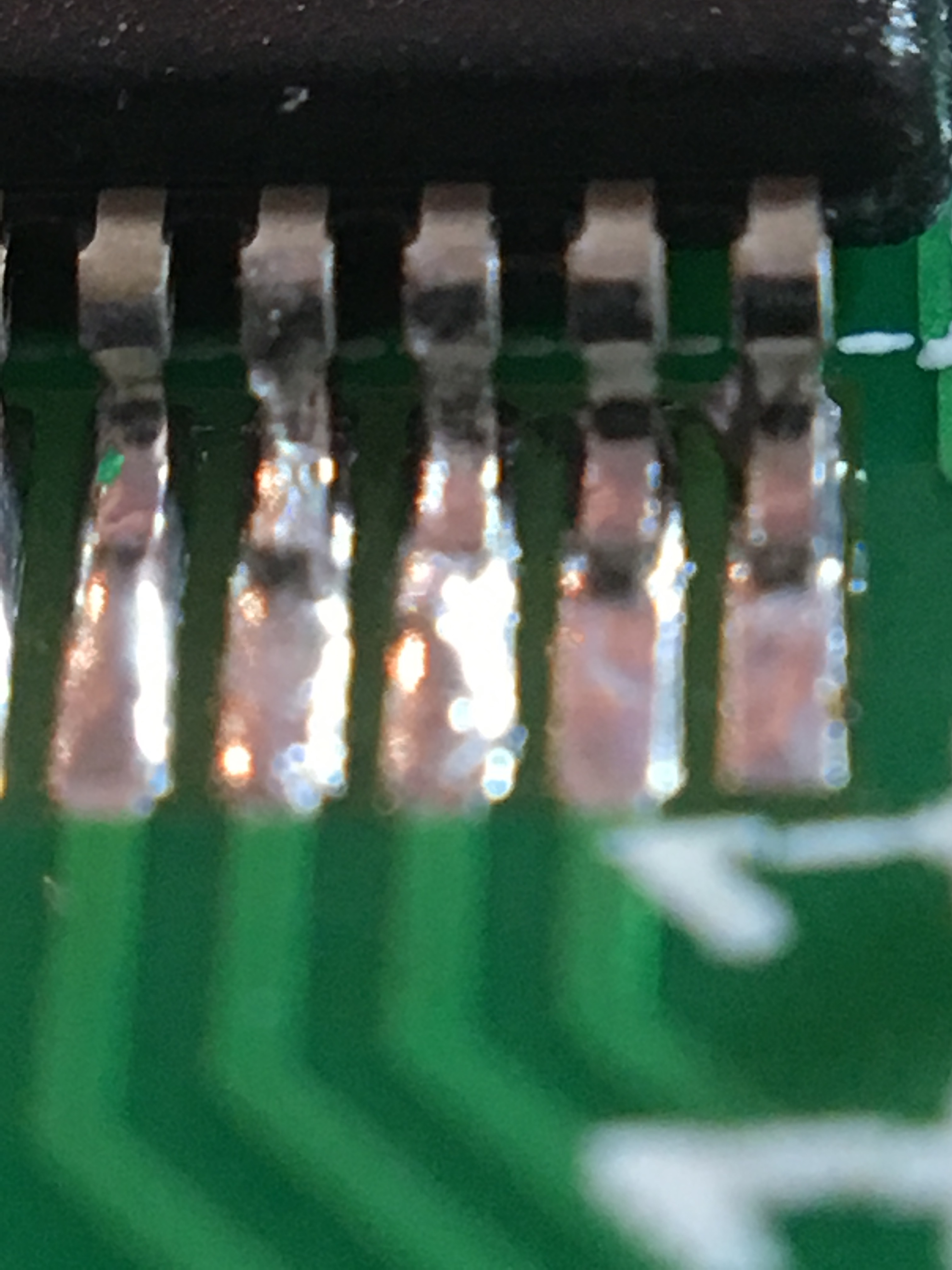
With the corners tacked down, it’s now time for the main event- soldering the rest of the pins. There are various techniques for this, but I opted for the “drag soldering” method. Again, in violation of all previously-held good habits of soldering, this is simply putting a blob on the iron and dragging it over the pins. Because the pads and pins are clean and fluxed (right?) and the traces are covered with solder mask, the solder really only wants to be on the pins and pads anyway. If you use too much solder, you will get some bridges between. If you use a lot too much solder, you will get a lot of bridges between pins. Guess what I did.
As you can see, I pretty much bridged every pin. Amateur hour, indeed. Especially when you consider that I have done this a lot before. It’s been a while though, and clearly I am rusty. However, don’t panic! We can fix this.
Cleaning up the bridges was a long process because of how poorly I did this step, but a combination of techniques got it done. If you’re good at drag-soldering, you’ll typically get one or two bridges at most. Often none.
For the really big blobs, I used my Hakko 808 desoldering gun. This is a sledgehammer as SMT instruments go, but luckily you only have to get it vaguely in the correct area to suck up the excess. The nice thing about SMDs is that very little solder is actually needed on each pin. So little that the desoldering gun will not likely be able to remove too much. Desoldering guns always leave a film behind, and that film is all that an SMD needs.
The second technique used is desolder wick. For areas that are too small for the desoldering gun, but there’s still a pretty substantial blob or bridge, desolder wick gets it done. I find it helpful to dunk this stuff in flux, and apply a blob of solder to the iron. Solder conducts heat way better than metal-on-metal, so having a blob of solder between the braid and the iron on the back really helps. It’s also important to keep the braid moving. Leaving it one place, it’s easy to overheat the pin or pad.
Once you’re down to the really small bridges, then it’s time for the “dry iron” technique. This gets the whiskers between pads, and importantly, the bridges across the backs of the pins that can be really nefarious. The trick here is simply to give your iron a good cleaning in the brass wool so that there’s no appreciable solder on the tip. For bridges between pads, simply swipe the crack between the pads, back to front to clear the bridge. For those nasty bridges across the backs of pins, stick the point of the iron straight in between the pins. The finest point tips from Weller are fine enough to do this. Melting the bridge will break it, sending the solder to the pins on either side, or on to the iron. Either way, you win and evil loses. The trick to this is that your iron has to be perfectly parallel to the pins. If it isn’t, it’ll seem like you can’t reach back in far enough. Trust me, you can with the correct angle. When doing the dry iron technique, clean the iron after every single bridge that you fix. If you don’t, solder will accumulate on the iron and you’ll make bridges worse when you touch them.
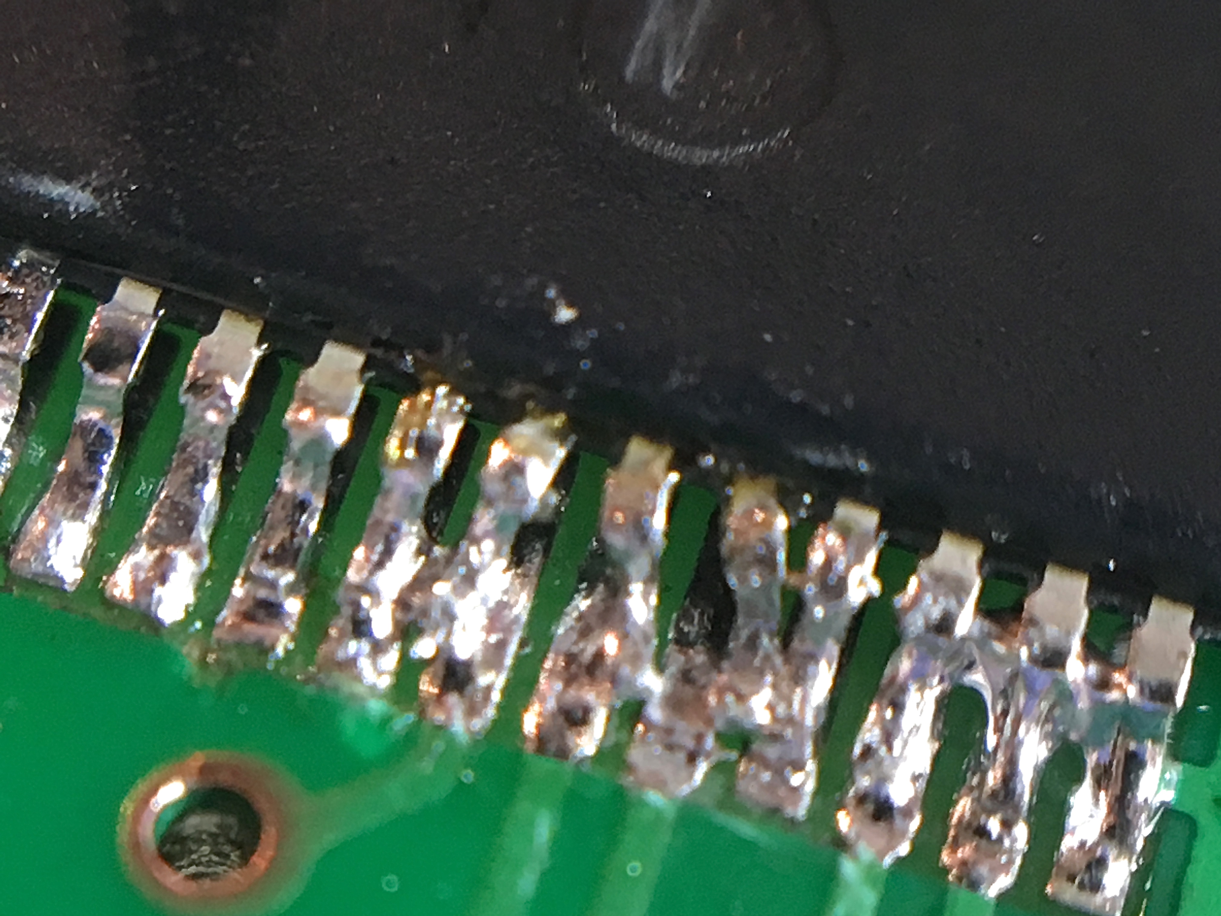
Bridge clearing went well, but I did mess up one part of this repair, unfortunately.
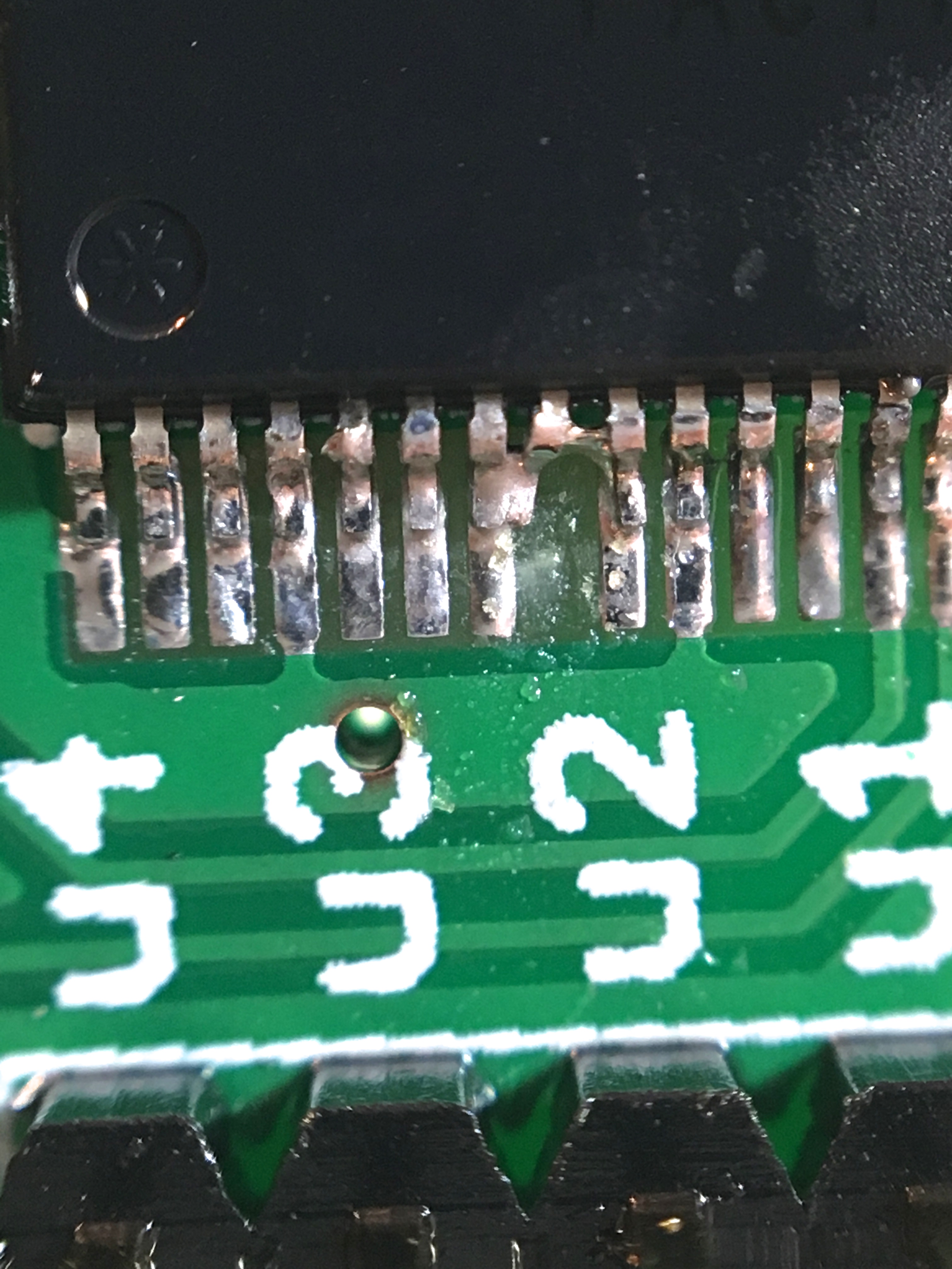
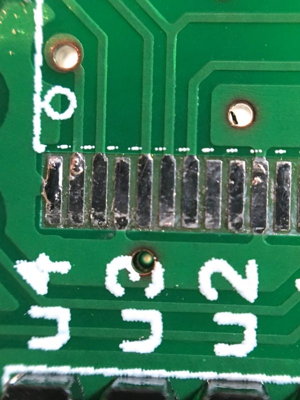
Pins 7, 8, and 9 are kind of a mess. I lifted the pad on pin 8, the pin got bent, and all three pins are bridged. Is this catastrophic? Not at all. A quick look at my photos from the PCB under the chip shows that none of those pins are actually in use. From the datasheet for the chip, we see that one of the pins is Vcc and the other two are inputs. So all I have done is tied two unused inputs high that were previously floating. This seems entirely harmless, and the best course of action seems to be to let sleeping dogs lie here. If I get aggressive about trying to repair that, I could do more damage.
As mentioned, I’m too cheap (as of this writing) to invest in a binocular microscope. However, I did make extensive use of the macro lens attachment that I happen to have for my phone. You can buy these things online for any brand of phone, and it was a surprisingly effective way to tackle this problem. The main challenge is that the focal length of a macro lens for a camera is much shorter than a microscope designed for soldering work, so you only have about an inch of space between the lens and the PCB to work in. You can do it, though, and it pretty much enabled this repair. I have a head-mounted magnification visor (the standard cheap one we all have), but it tops out at 10x and the lenses are not very good. It really wasn’t sufficient to see what I was doing here. I used the macro lens two different ways that both worked. I held the phone suspended over the work with a helping hands device, and I also just held it in my left hand while soldering with the right. That latter approach doesn’t seem like it would work, but it actually did. The trick is to find an angle where the camera can see what you need, but you can still get the iron in underneath it.
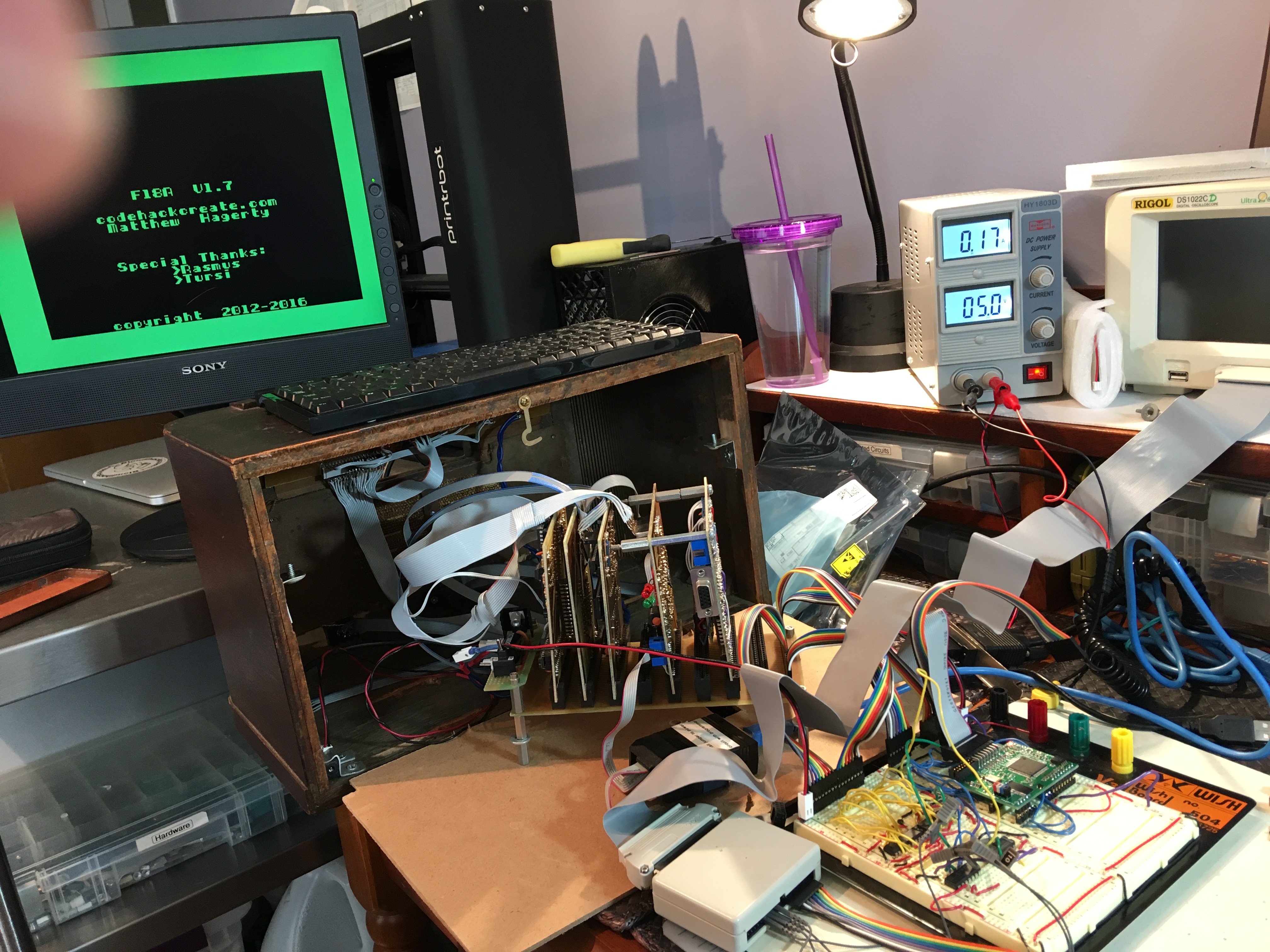
At this point, it seemed like maybe everything should work. I had inspected the chip to the best of my ability, and all my solder joints looked good. If I actually repaired it, I should be able to power up the device, and Veronica’s boot sequence will turn the border white (I added that code to the ROM startup for easy testing).
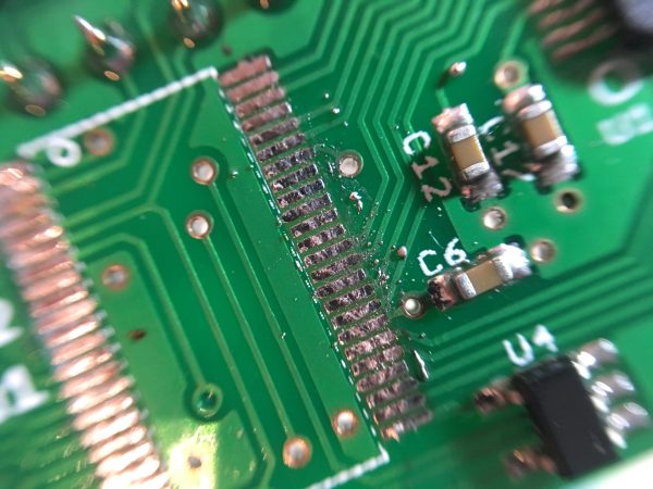
Not discouraged, I got out the logic probe and tested the data bus again. With the F18A deselected, the data bus should all be tri-stated, which sounds like a confused low buzzing on the logic probe. I found that a couple of pins were still being driven low. That was the symptom that prompted this entire repair in the first place, so it could be rather discouraging. But wait, this could also be a solder bridge, so I took a harder look at the affected pins.
One of those pins is ground, and the other two are data bus pins, so this could certainly explain them being driven low. Using the dry iron technique, I was able to poke straight in there and clear those two bridges. This also taught me another camera angle to use for my inspections. On parts this small, camera angle matters a lot. If you don’t inspect every joint from every angle, you can easily miss something like this. I needed to view the gap between the pins from straight-on at board level to see those bridges. I then inspected all the other pins from this newly-discovered camera angle, but the others were all okay.
After all that, it was time to power it up again. How’d we do? If it worked, then the border will turn white a few seconds after boot:
I gotta say, seeing that border turn white was one of the greatest moments in Veronica’s history. This is a project with some very hard-won victories in it (*cough*5yearsToBuildAGPU*cough*), but this was definitely one of the best. The amount of self-doubt I had for this repair was immense. I honestly didn’t really believe I could replace that bus transceiver successfully. This class of SMT rework is well above my pay grade and it’s a next-level accomplishment for me. I won’t lie- there was shouting, arm pumping, and dancing inside Dunki Freehold when that border turned white.
More challenges await, but we’ll leave things here on a high note. Veronica’s new graphics system may well have been clawed back from the abyss of certain infinite doom. Also Chip Quik is pretty nifty.
WIN!
😀 😀
Hello! I’m glad I accidentally found your YouTube Channel a few days ago. It seems that April 6th, 2016 was the last time I had seen your blog, and you have been awfully busy since. Great to see that Veronica is still a healthy, probably not broken project. I am so sorry that it took me so long to come back.(in my defense, my laptop broke, and at that point, your blog was part of my browser’s startup routine, and I went over a year without a computer)
I think your machinist adventures are nifty.
Sorry, that wasn’t supposed to be a reply, it was supposed to be it’s own comment.
Thank you, and welcome back! 🙂
My preferred macro lens: https://www.dropbox.com/s/41m64mwwg6bohqu/2019-06-30%2019.51.11.jpg?dl=0
I’ve got a couple at the bench for those annoyingly tiny jobs.
In use: https://www.dropbox.com/s/rvwmfbkfzxxevvc/2019-06-30%2019.56.30.jpg?dl=0
(very fashionable…)
If the SMT chip you’re removing is already broken, or you don’t need it, you can try cutting the pins, and then desolder them one by one. There’s even “chip cutter” nippers designed for this purpose.
I’ve used pin cutters, and I’ve lifted pads using them. The cutting action on the ones I used slightly twisted the pin as they cut. Totally a YMMV, and it may have been user error, but man was that frustrating.
I’m doing a ton of this right now, and because of a design problem, I get to lift two of the pins and insert a 0201 resistor in series with the pins. My new habit: test continuity between adjacent pins to find shorts before powering up, because otherwise there is crying.
Yikes! That sounds challenging. 0201s are like grains of sand.
What a big win for you Quinn!! Nice feeling 🙂
Thanks! It sure is. 😀
Nice!
I routinely use a knockoff version of https://www.amazon.co.uk/Dremel-Versatip-2000-6-Soldering-Accessories/dp/B000QGC6XW for such repairs. The hot air attachment is accurate enough for anything other than very small 2 pin components (and those are pretty easy to hand solder anyway). For this sort of fix, running the hot air back and forth over the chip will melt all the pins at once, and the chip can be removed with tweezers. After cleaning with isopropyl alcohol, a tiny amount of solder paste can be applied to each row of pins (if there isn’t enough left on the pads), or some flux. Then, hot air again to solder the chip. You shouldn’t get any bridges.
I’m sure a “proper” hot air station is better, but this has worked for me many times, plus it is a useful tool when soldering stuff outside or in the car, and its cheap.
That’s a neat idea! I haven’t seen that tool before. Thanks for sharing!
Reading this, I was thinking about masking the rest of the board with mylar, putting some solder paste down and having a go with a small hot air gun. Never did it in a serious project like yours, though. Do you think it would have worked?
I have heard of people doing that, yah! You can buy ends for some hot air guns that focus the heat in a small area.
Bought a cheap Chinese rework station years ago, still doing just fine today. Only complaint is the soldering iron isn’t the best I ever used, but the hot air portion works pretty well. Both are even somewhat temperature accurate. Think I paid 150-200.
Since you just need the hot air portion you might look at the Quick brand, they were the best when I bought mine and reasonably cheap unless you intend to go into the deep end and get that commercial level stuff.
Sorry for being so late to the party, my email is backed up at least 2 months. If only I could make a living doing retro-computer work. 🙂
Good to see you found ChipQuik, it is my go-to for removing QFPs for sure. Cleanup is easiest with a hot-air bath, Q-tips, and alcohol (I recommend the 99.9% stuff from MG Chemicals). ChipQuik does not wick very well. You can also add more solder to saturate the ChipQuik to get it to wick better. Like you said, keep it clean and use lots-o-flux.
For sure SMD (re)work can be nerve racking the first few times, but now that you have taken the step it will soon become old-hat. The *key* to SMD work is the solder-mask, the PCB absolutely has to have one, and being able to see what they heck you are doing. I always work under stereo magnification. The 0.5mm pitch QFPs are not so bad, but I find the QSOP to be a pain, especially that level-shifter! The 245 on the F18A is harder to solder than the FPGA! Actually, it is the hardest IC on the board to solder, IMO. Good job getting it working! At this point I’m not sure if I should mention the flat-fee repair service I have on my website… 😉
The three shorted FPGA pins you found a few posts back… That was a lesson I learned the hard way, The F18A was my first real serious SMD PCB, and connecting pins directly together like that with a trace is something I will never do again. They always cause what looks like a solder bridge.
The F18A MK2 will get finished, but coming up with a solution for the video output problem has set me back literally a year (I refuse to put myself into a legal situation over a hobby). I’m putting cycles into it again though, and it will happen.
Interfacing the 9918A was usually done using two “ports” (two separate memory-mapped or I/O addresses) called the “status port” and “data port”. The ColecoVision (Z80 based) has a really simple circuit example for interfacing the 9918A, and there was also an Apple][ 9918A video card! It used a single logic IC for decoding (details can be found around the ‘net, I don’t have a link handy). Basically the LSbit of the address bus would go to the MODE pin, and the CPU r/!w was split into the two required signals that were passed to the F18A when the decoder enabled them.
The F18A is faster than the 9918A, so while it is fine to follow the specs in the datasheet, the setup and hold times are going to be that of the FPGA (plus the 5-ish nanosecond delay of the 245), which is going to much faster than anything a 6502 can do. Worst-case access cycle for the F18A is about 70ns – for the entire read or write cycle.
I hope this helps some. I’ll send you a proper response via email as well. Again, my apologizes for the delay.
Woohoo! Thanks for writing, Matthew! I adore the F18A. It’s filling a huge void in the homebrew computing community. A decent graphics processor that is easy to interface with is immensely valuable.
Any suggestions you have for why the transceiver keeps burning out on me would be much appreciated! I’m still unsure what the problem is. I haven’t had this happen with any of the various things I’ve attached to Veronica over the years, and I’m scared of it happening again.
It is good to know the F18A is being used in a home-brew system like this. It is these small rewards that help drive the enthusiasm to keep going.
I’m sorry the 245 keeps blowing, I did not know the part would be so sensitive to voltage variations. I think you have come up with some good solutions in your other blog post and subsequent replies, so I won’t add duplication here.