This idea may yet see the light of day.
A while back, I had this idea to create a thing that would turn an Apple IIc into a laptop. Unfortunately, this project has pretty much been one set back after another ever since. Most recently, I decided maybe I didn’t want to fill my oven with toxic fumes after all, and abandoned my plan to vacuum form the shell. Building a vacuum former was fun, but after talking to a friend with a lot more 3D printing experience than me, I decided to give that another whirl.
I made some changes to my design, most notably adding more structural ribbing on the underside. This was pretty easy to do. I already had tabs in the model for holding the LCD panel and control board, so I simply extended those to the edges to form stiffeners. If it was still warped, my friend and I had some ideas for how to straighten it.
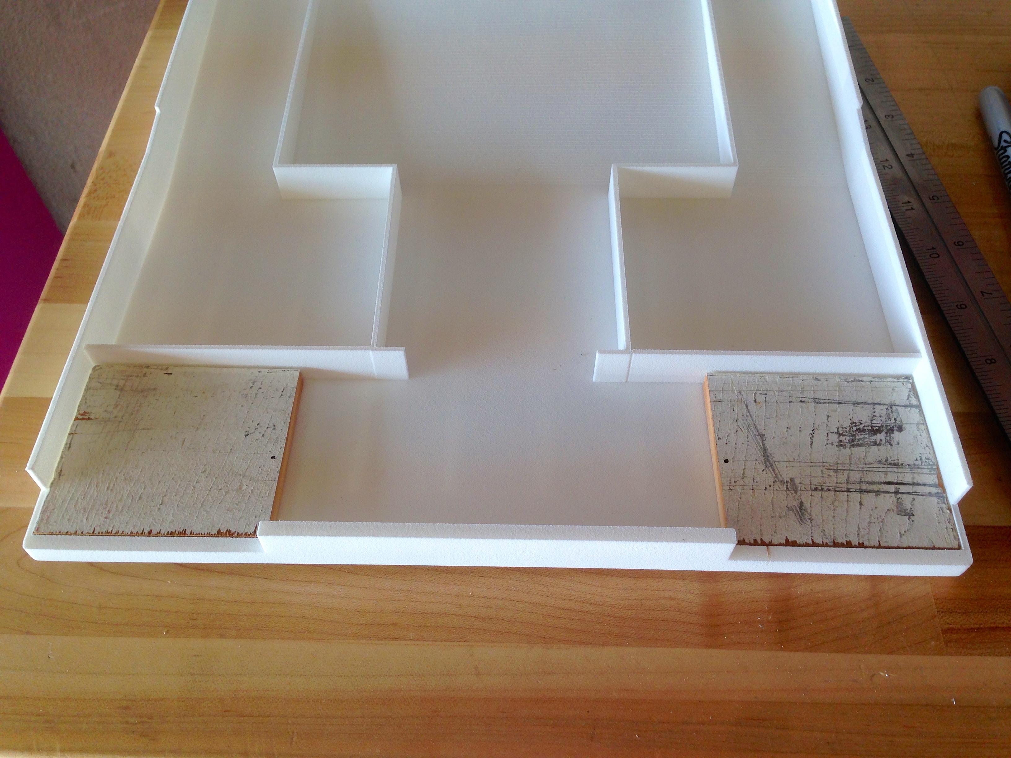
The 3D print came in, and it was warped a little bit once again, but much less than before. It’s definitely usable this time around. The warping basically sorted itself out as things were mounted to the shell, as we’ll see.

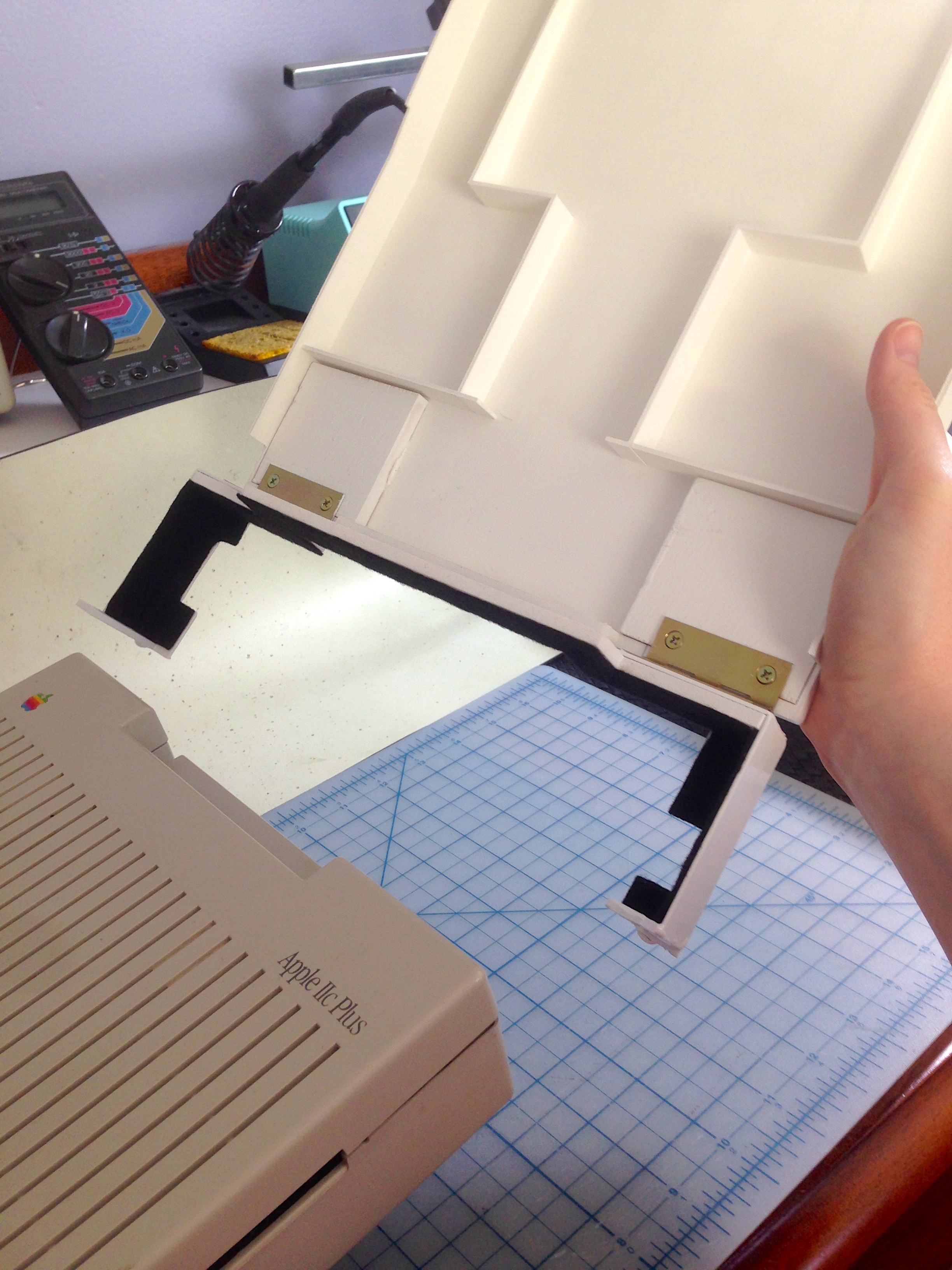
Some things to note about a Shapeways print if, like me, you have never done this before. This is their basic “flexible and strong” plastic. It’s the cheapest material they offer, though it still isn’t cheap. They are Selective Laser Sintering prints, and they feel like what they are- nylon dust glued together really elaborately. The surface feels like fine-grain sandpaper, and it has a kind of “grit” on the surface that never seems to come off. It feels like it needs vacuuming, but vacuuming doesn’t help. This material is pretty strong, but my model was a little too thin in places. I would not go less than 4mm for anything structural. The sidewalls that you see above are 2mm, and the top edge split a bit at the seam. The precision of the process is impressive. You can actually see little sub-millimeter errors that I made in my 3D model. If anything, I was more limited by the precision of the modeling software (the free version of AutoCAD’s 123D Design) than I was by the SLS process. Most of the issues are not printing problems, but rather, small errors in the 3D model that I couldn’t see in the software. For example, my split seam is likely because the polygon edges are closer together in that area than it appeared, or there’s some other oddity in the geometry that I couldn’t see in 123D. I don’t blame Shapeways’ process for this. Giving yourself some margin of error in the geometry is a good idea for structural areas or weird angles.

Here’s the 123D model for this. I went back and forth on whether to offer this up for sale on Shapeways or give it away here. I’m opting for the latter. If you want to support Blondihacks in such endeavors, become a Patreon patron of Blondihacks. That’s how you can acknowledge my efforts. If you improve on this design, or try it out yourself, let me know!
One of the gotchas with 3D printing is that you have to anticipate every contingency ahead of time. If you make any small errors in your design, you may end up reprinting it, which is very expensive. If, like me, you need to make some small alterations after the fact, there are options. It drills nicely, and takes wood screws quite well with a pilot hole. Cyanoacrylate glues work very well, as does the water-cured Gorilla Glue brand adhesive. The latter is especially nice if you need to glue it to a dissimilar material such as wood. For making large scale cuts, I found tin snips work really well. For more delicate cuts, I found the metal cutting wheel on the Dremel worked the best. It actually just melts the stuff, but this seems to work better than any other method. The melted blobs around the “cut” are easily removed with a knife, leaving a clean, sharp edge. This works for notching and beveling as well. I wore a respirator while doing a lot of cutting, because it smells really bad when it melts, which probably means it isn’t good for you. Also eye protection of course, but I assume that goes without saying.
I can’t proceed without a word on price, however. This shell was close to $250US. I know, I know. That’s vastly more than I would usually ever spend on a project like this, but it was an interesting learning experience, and the end result is pretty cool. Call it tuition to 3D printing school. I’m now seriously considering buying a 3D printer of my own, because it would pay for itself after a few more projects like this. If you’ve ever wondered why 3D printed things you buy on Etsy or Tindie seem so “overpriced”, this is why. 3D printing is damned expensive right now. I imagine the price will come down in the coming years, but right now it is a luxury process. The end result is undeniably attractive, though. With very little effort, you can chamfer edges and corners, for example, and make all kinds of complex shapes that would be very difficult any other way. For certain kinds of jobs, this process is definitely worth the price.
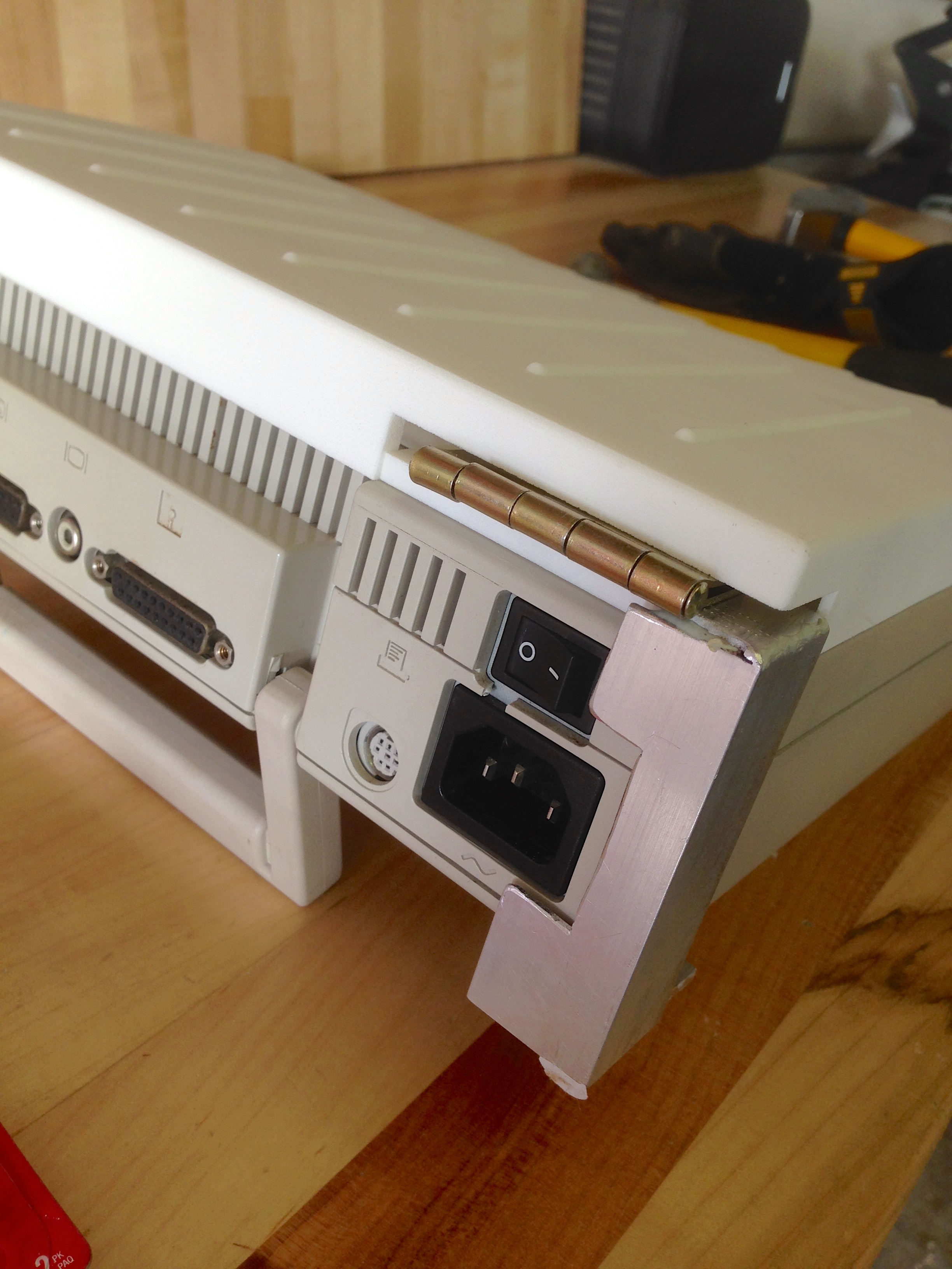
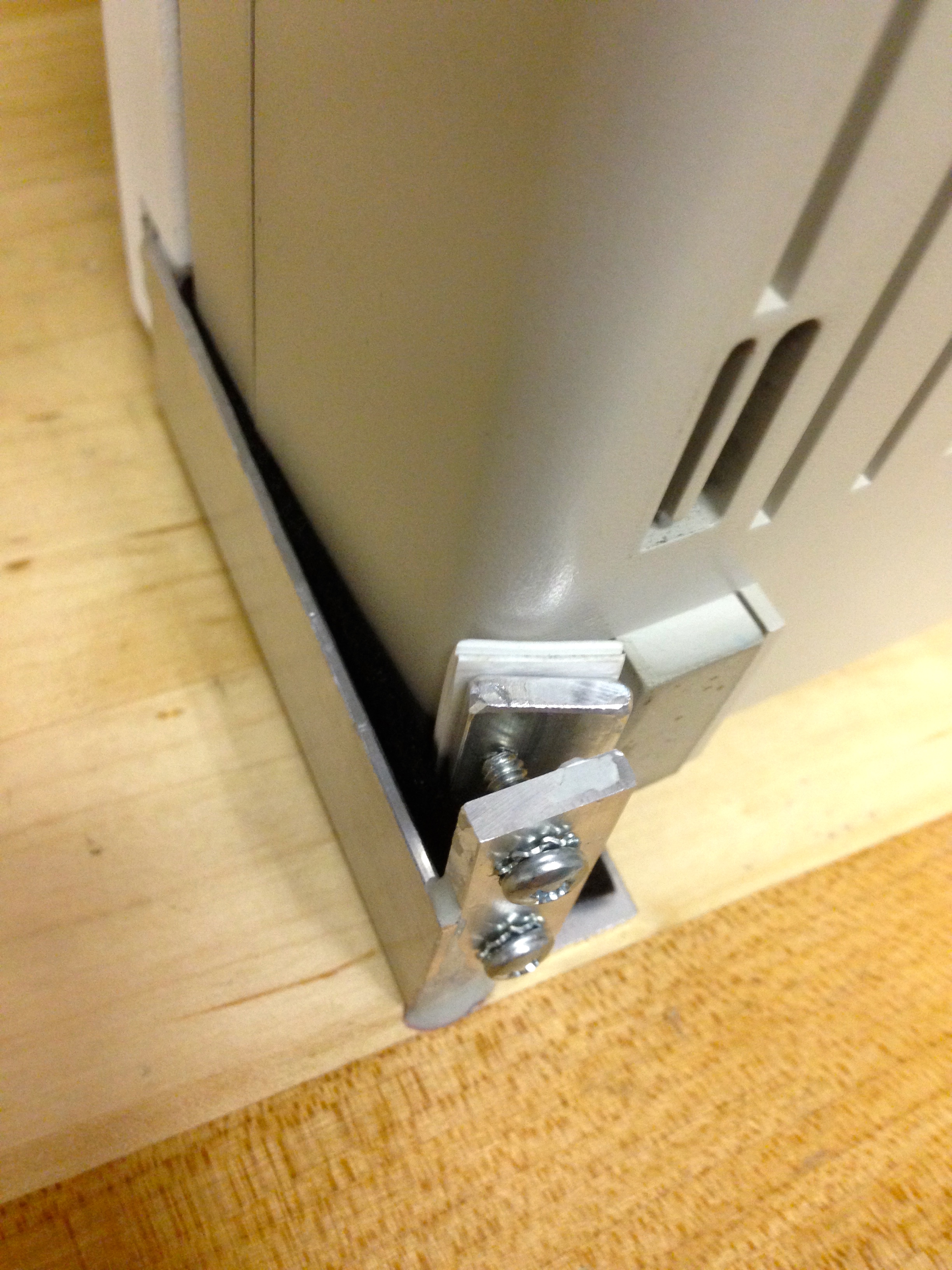
With the shell looking good, it was time to move on to the mounting system. It’s important to me that the Teddy Top mount non-destructively to the computer, because this IIc Plus is pretty special to me. Since there are no handy mounting points we can use, that really only leaves one option- some sort of clamping system. The clamps have to be very odd and complex shapes, however, so I knew this was going to be a fabrication challenge. I started with aluminum angle stock, and with a couple of strategic bends and cuts, I was able to form almost the entire shape from a single piece. I needed a thicker piece on the bottom to take a threaded fastener (as will become clear in a minute). Joining thin, small aluminum pieces like this would be best done with a TIG welder, but that’s beyond the capabilities of my home shop (and its owner). Instead, I used the hacker’s TIG- JB Weld. This stuff is a flavor of epoxy tailored for metals, and if you prepare the surfaces carefully it actually works pretty damned well. It’s impressive stuff, to a point. It’s no replacement for actual welding, but as glues go, it works better than you might expect. In the automotive world, just about every racing team has a story about JB Weld repairing something during a race that should have put them on the trailer.
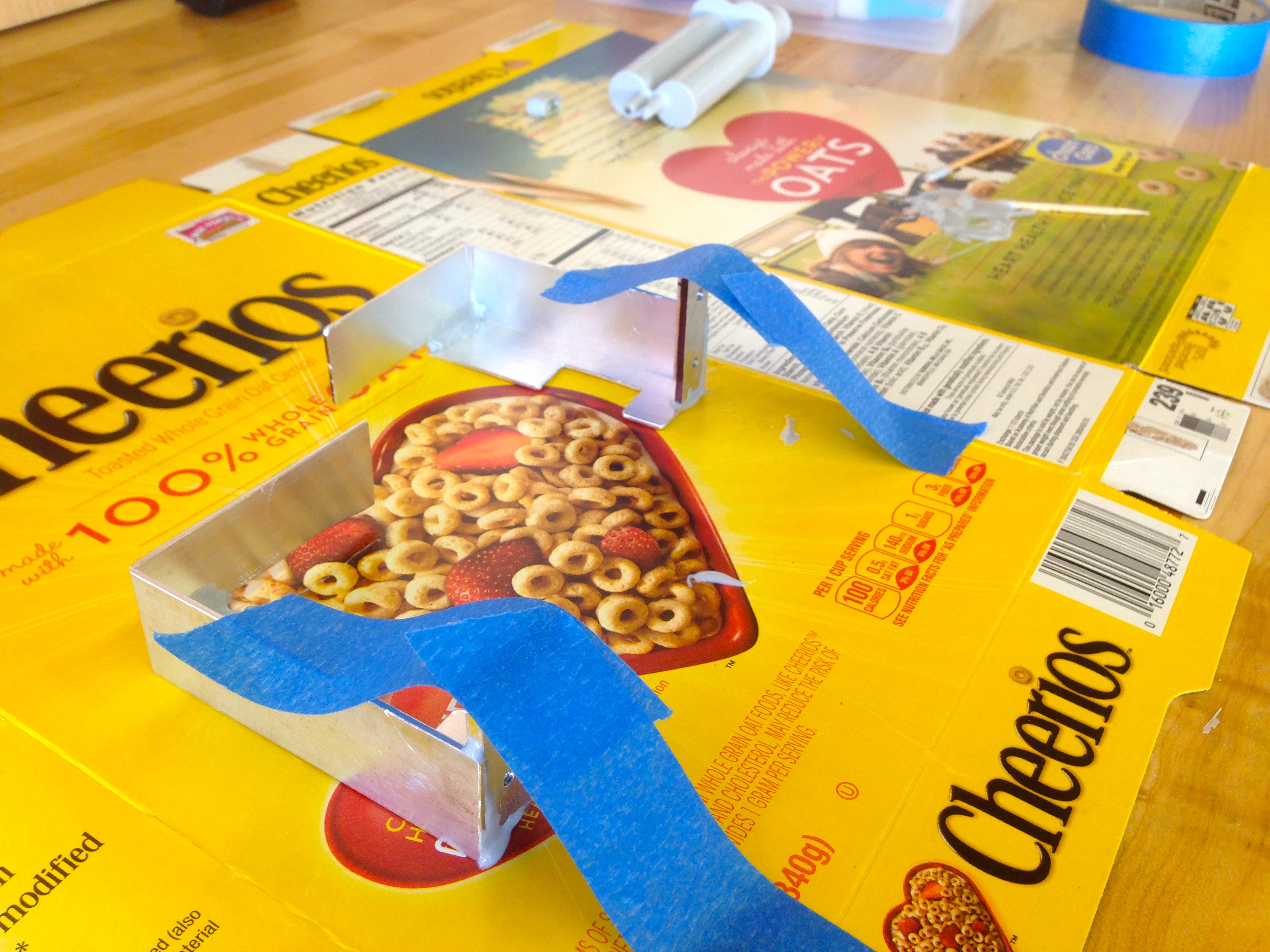

In that photo, you may also notice there’s plastic under the top of the clamp as well. This is a separate piece that I 3D printed along with the shell to hold the hinges along the bottom. It’s a special shape, because it needs to jog around a cut out in the top of the case where the handle folds up.
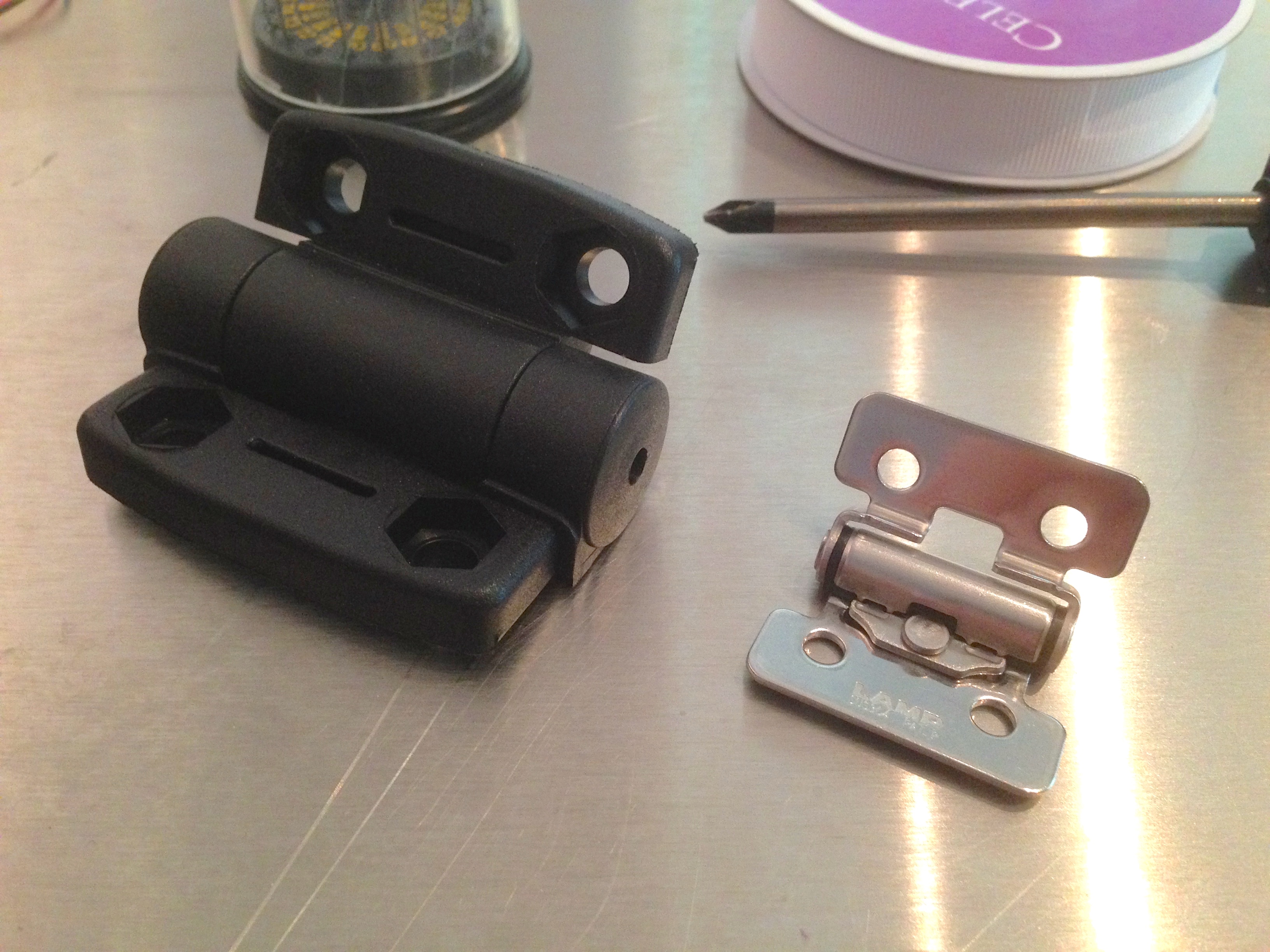
With the basic clamps done, the next challenge was hinges. Modern laptop hinges are an unsung triumph of engineering. They hold up something fairly heavy, yet allow you to effortlessly and smoothly open them to any angle, where they will stay until the heat death of the universe, or you decide to adjust it (whichever comes first). They also take up almost no space, and limit range of motion as needed by the electronics. All of this is not easy to achieve. The common term for this construct is “friction hinges”, and I made two attempts to buy them. The problem is that the ones you can buy are intended for things like cabinet doors, which have a lot of weight on them, and a lot of leverage as well. They are much too stiff for this application. You can also buy adjustable friction hinges, which allow you to tune the stiffness. This is quite a neat idea, but these turn out to be very bulky. A couple of expensive experiments later, and the junk pile has some fancy hinges sitting on top of it now.
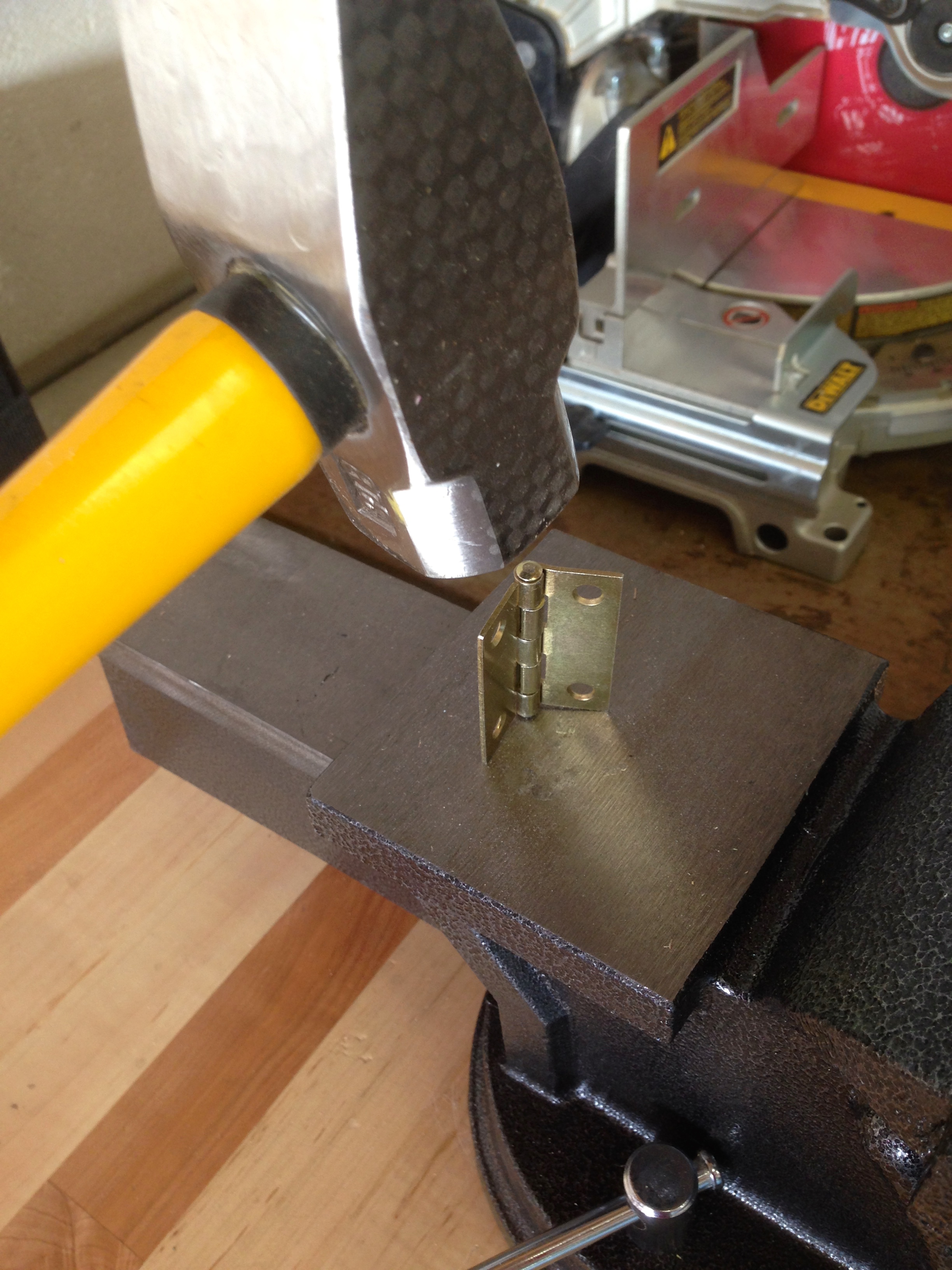
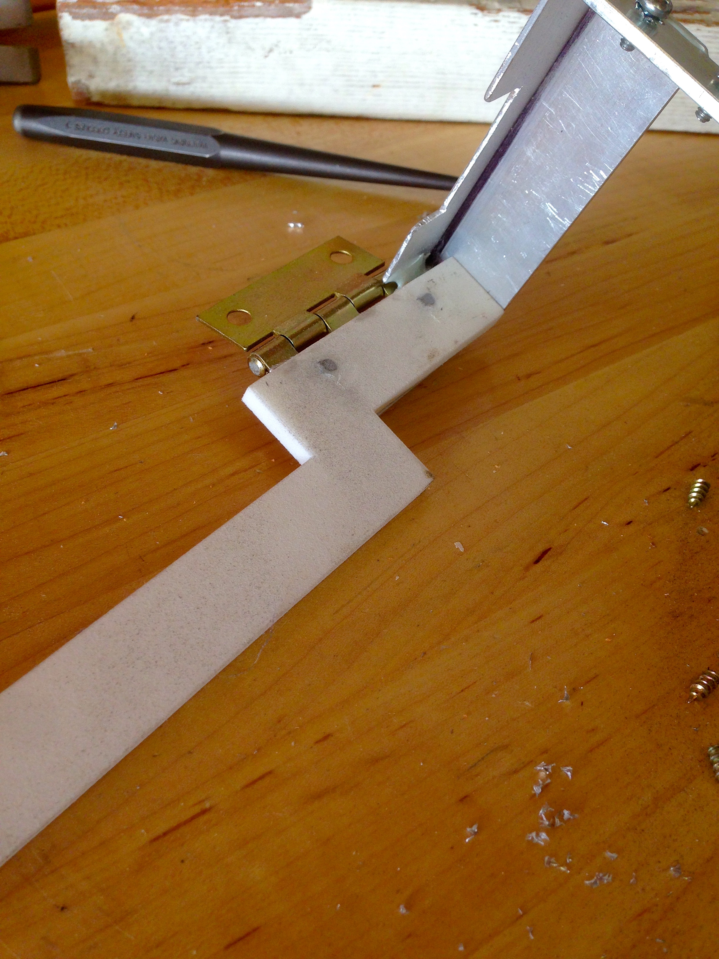
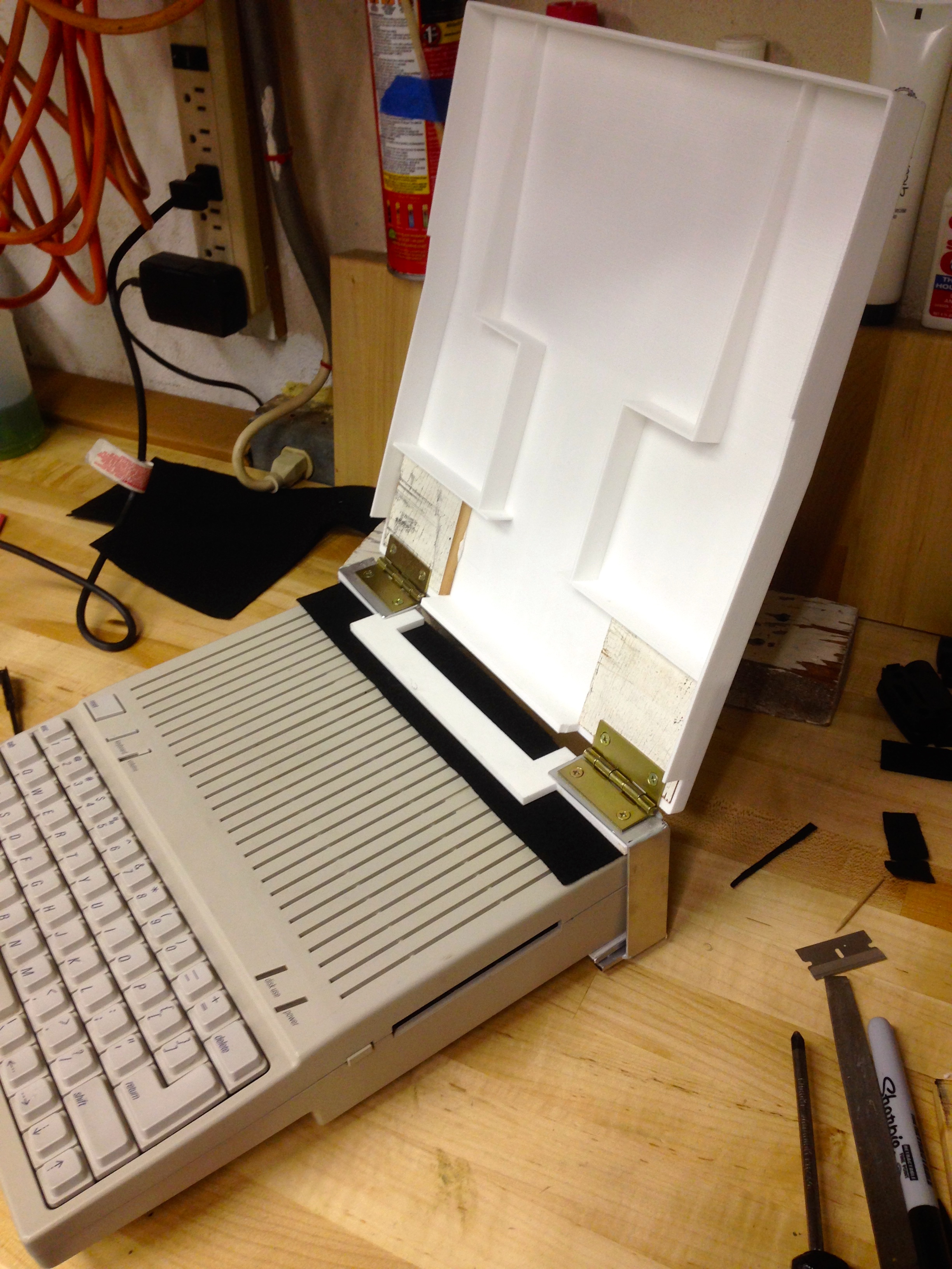
Then, inspiration hit. I didn’t necessarily need a smooth, precisely torque-rated friction hinge. I just needed a hinge that’s a bit hard to move. In other words, a poorly functioning hinge. I can make that! I bought some regular brass hinges from the hardware store, and proceeded to jack them up real good with a 3lb sledge.
Next I needed to mount the hinges on the hinge plate. For this, I used some wood screws, and cut them flush on the bottom. The SLS material seems to take wood screws quite well (with a pilot hole, of course).
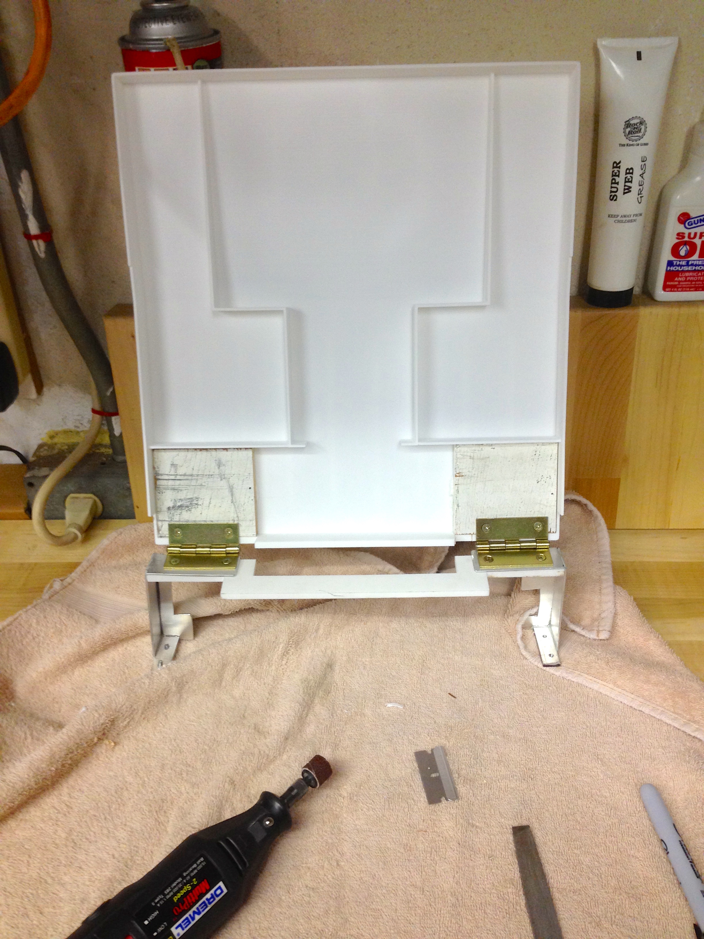
Then, naturally, the hinges need to be mounted to the lid. This was an area that I didn’t spend enough time thinking about when building the model. Some part of my brain said, “Oh, I’m sure I’ll figure something out for that”. Well January Quinn, now February Quinn has to make good on that. Thanks a lot. I decided the plastic needed to be thicker where the hinges mount, both for support, fastener holding depth, and alignment. Rather than go back and reprint the whole thing, I added some pieces of wood. They’re attached with Gorilla Glue, which is a unique water-cured adhesive that works well on a wide range of materials. It’s my go-to when gluing dissimilar things like wood and plastic. This stuff takes some practice to use. The water is critical, clamping is very helpful, and be aware it expands a lot while curing. Once you get used to its peculiarities, it’s good stuff.
Now we need to finish the clamping system. My original plan was to use thicker material on the bottom of the clamps, so that I could drill and tap for screws. These screws would then press against another plate that rests against the computer, applying pressure to hold everything, without marring the plastic in any way.
While fiddling with that, trying to get it to work, I noticed the rubber foot next to my clamp. It has a plastic ridge next to it. This could be perfect! I could make a little piece that would anchor against that, and make it thread into the same holes as my original clamping plate, for tightness adjustment.
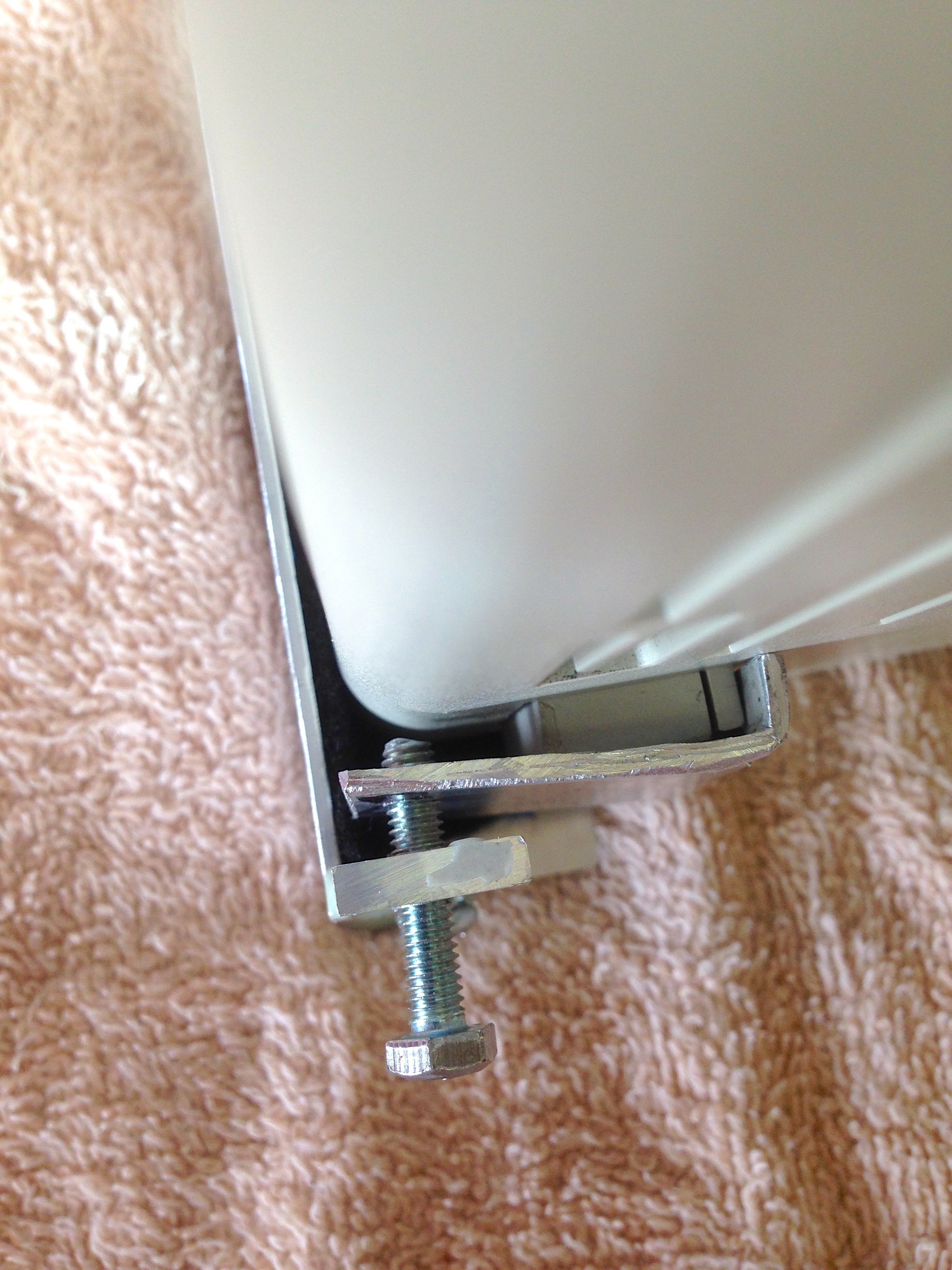
A quick protip on shortening bolts- thread a nut all the way on to the bolt before cutting it (with the Dremel diamond wheel, naturally). That way, if the threads get a bit messed up by the cutting and filing, they’ll get cleaned up when you remove the nut. Also, when cutting a bolt, you’re losing the starter thread. This will make the bolt trickier to get started in a threaded hole. Another tip is to turn the bolt to the left with gentle pressure against the hole. You’ll feel it “click” when the threads are lined up and you can then start turning to the right to thread it in. This is a common mechanic’s trick, since you’re often threading fasteners blind on a car, but it also works great on cut bolts with no starter thread.
In order to unify the wood pieces with the design, and also give a nicer finish to the SLS plastic, I opted to spray-paint the whole thing. Any project worth doing is worth a little rattle-can love.
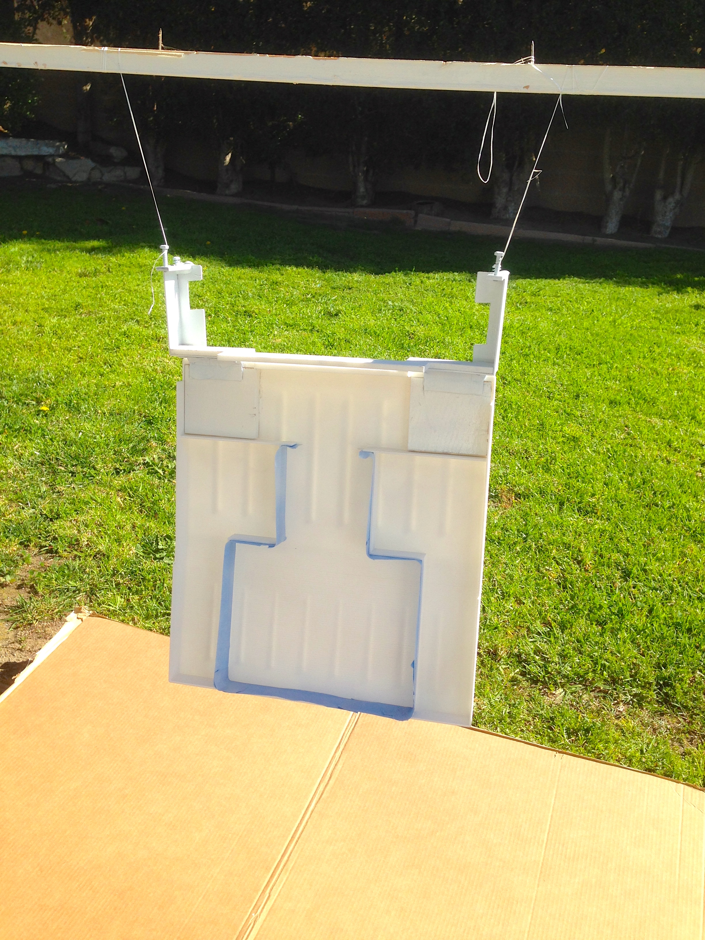
Painting also seals the surface of the SLS print, which makes it much nicer to the touch. I’d recommend some kind of spray coat for any SLS 3D print, if this is how they usually are.

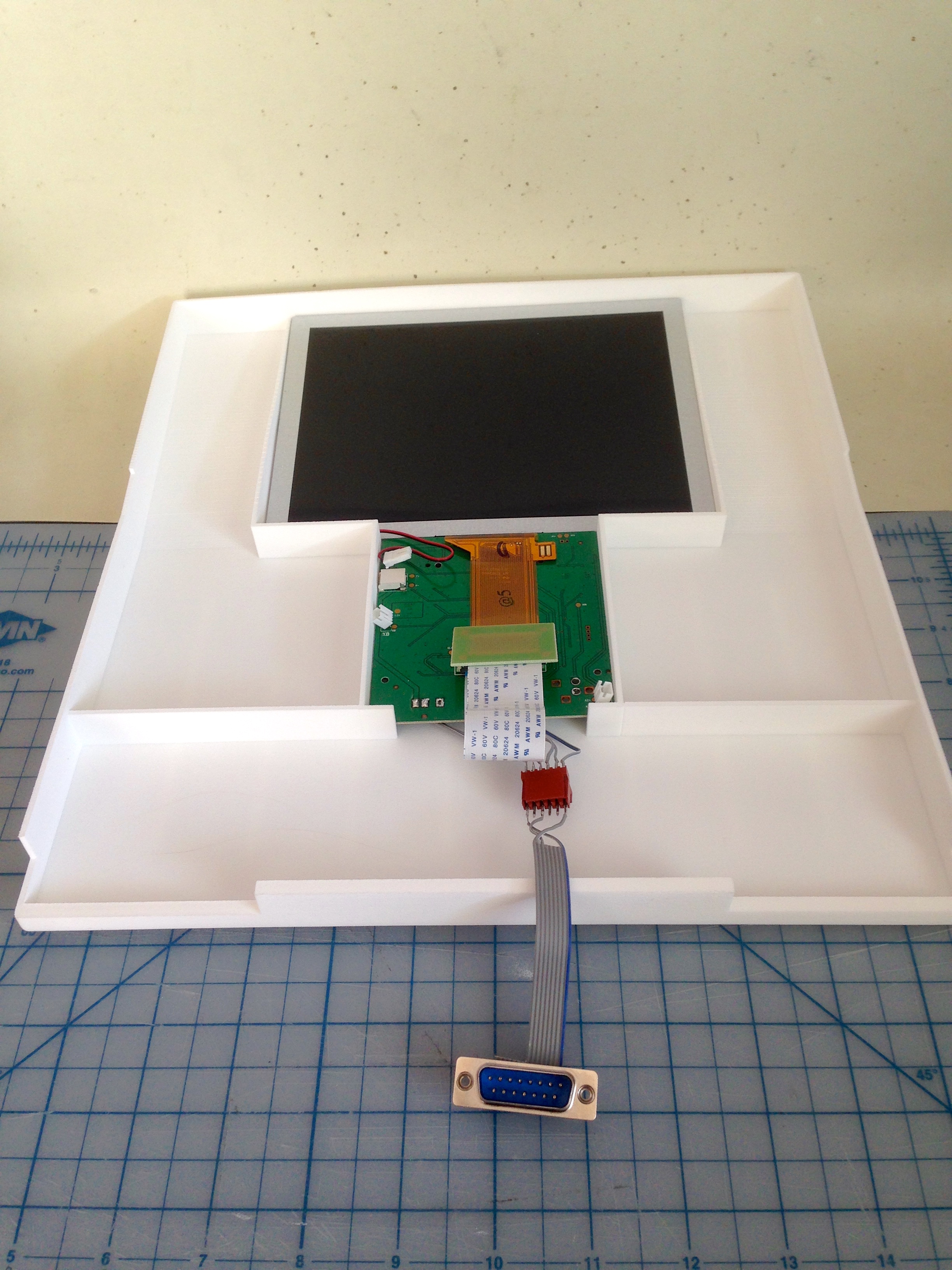
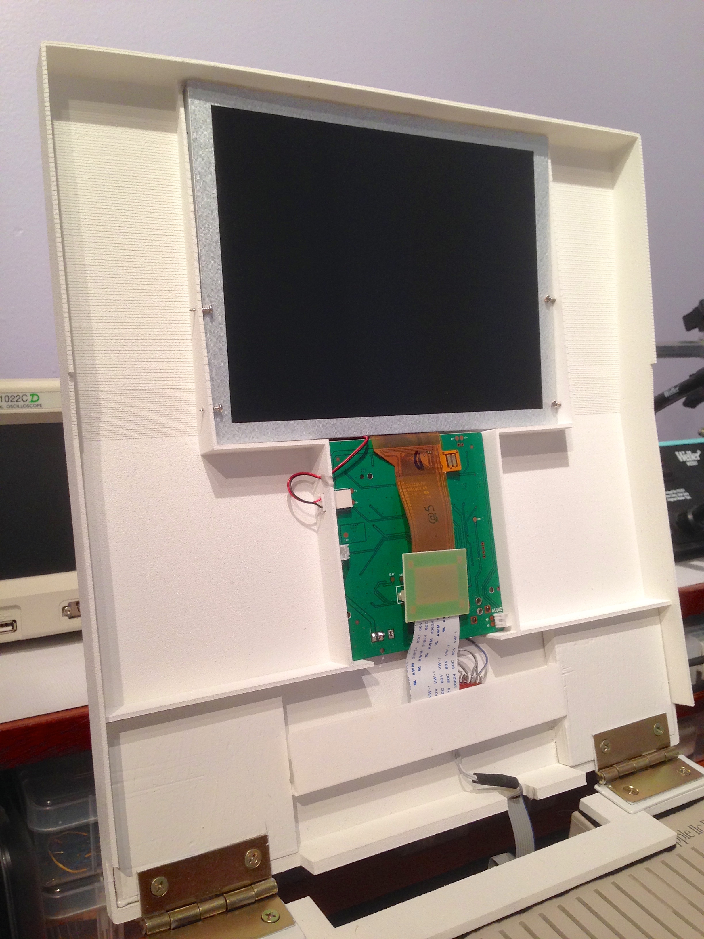
The next step was to get the electronics installed. I needed to clearance a few things, and add a couple of mounting screws, but for the most part, my planning in CAD paid off here. Everything fit together just like I had hoped way back when I did the foam core mockup.
I was hoping the LCD and driver board would simply be a friction-fit, but that wasn’t quite enough to hold them securely. Instead, the junk pile coughed up some tiny little self-tapping screws, pilfered from who knows where. Haveth ye faith in the junk pile, and the junk pile will provideth for thee.
There was one small clearance issue with the driver board. The power connector for the backlight needs to exit stage left, but my plan was to desolder it and reorient it. The connector proved resistant to all forms of desoldering without destroying it in the process, so instead I cut a hole in the rib for the plug to pass through. This had the added benefit of helping to secure the PCB.
This is still a rough prototype of what Teddy Top could be, but so far it is achieving all my goals:
- Flip-up LCD display with no external power source.
- No interference with the Apple IIc’s carry handle.
- Non-destructive mounting system.
- Still fits in the original Apple IIc carrying bag.
- No interference with any ports or features on the back or sides.
- Compatibility with the IIc and IIc Plus
To demonstrate success on all these points, here’s a demo video.
I’m pretty pleased with how this turned out. There’s a few things I would change in the 3D print, such as support for mounting hinges, and retainers for the wiring and LCD. I think I would also try designing the hinges right into the 3D models. I think each hinge half could be modeled in to the shell and bottom plate, respectively. Then a long thin bolt with a nylock nut could be put through, thus giving you a tension adjustment. I’m not certain it would work, but if I print this again for any reason, I’ll try it. Overall though, I think Teddy Top is coming along nicely. I have a few more ideas for things I want to add, so stay tuned!
3D printing… It still is expensive if you don’t have your own 3D printer for sure – or have a friend whom let you use his.
If you go the FFD way (Fused Filament Deposition) it’s not so expensive to buy or build one, and once you have it the plastic cost is really low.
More interestingly, there is a lot of possibility in the DIY field to decrease the price of building a 3D printer.
You potentially could make one for free – talking money here, not time spent – provided you have access to a scrap pile holding the right stuff and some tools.
To be practical, people who go the DIY way will usually buy at least the extrusion hotend, the motors and the electronics. I’d say this would be about 150 or 200 $ needed to bootstrap that kind of project.
If exploring the possibility of making a DIY 3D printer interests you I recommend reprap.org – you probably already heard about it, if not it’s an effort to try and gather all “opensource” solutions for autoreplicative fabrication machines. It has focused a lot on the fused filament model.
This could make a whole new season in your blog if you go that way, and I’m sure it would be enjoyable to read what your mind will come up with in that field.
Good info DeuxVis, thanks! I’ve been following the reprap movement with interest, but I think I would go with something more sorted like a PrintrBot Simple. It’s currently the most appealing of the sub-$1000 units to me. I’m looking for a tool, not a new hobby. From what I’ve read, even the “sorted” machines take a lot of calibration and futzing around to get working consistently and reliably. I would aim to minimize that, so rolling my own or buying those piles of cheap parts arranged in a printer shape from Aliexpress are probably not good for me.
I hear you there. For your first 3D printer build going with something well-tested makes sense, especially if you want something working soon.
Just make sure you go with a solution for which the “source” files – 3d drawings and models, firmware, etc – are available, I’m pretty sure you will want to make some improvements to your machine sooner or later, and having access to the design files makes it way easier.
I believe the printrbot fits that : http://printrbot.com/tag/open-source/
It also has a lot of users already, so you should be able to find improved/redesigned parts design and helpful tips all over the interweb : http://www.thingiverse.com/search?q=printrbot+simple&sa=
Oops, I meant PrintrBot Metal, but yes, your information is still great- thanks!
This is such a wonderful build to follow. Thank you for the updates!
The part I enjoyed the most was definitely how you “fixed” the hinges to suit your needs. Pure gold.
Thanks for taking the time to write up all your experience-building! A suggestion: if you know someone with a DaVinci 3D printer, ask for a demo. I was on the fence for 3d printers for a while, and bought a DaVinci 1.0 on sale for $400, figuring the parts were worth almost that much even if the machine was crap. Turns out, it’s not. All 3D printers are fiddly; cheap ones don’t seem any worse than expensive ones. AFAICT, almost all the variance in results comes from the experience of the user. 🙂
Achievement unlocked: Motivation to get my own portable //c back on the bench and finished.
As for friction hinges, the next time you need some, I have a pile of dead laptops you can scavenge from. Also, you can try taking a standard hinge, take it apart, and wrap the pin with some silicone tape. You may have to loosen the barrel to accommodate, then clamp or hammer them back together.
Aside from friction and gravity, is anything holding the display closed?
Friction and gravity, yep. Since the carry handle is on the back, this actually seems to work quite well.
Is one of the future additions going to be a faceplate, so the driver board is protected and the screen has a bezel? Or are you going to go for a more cyberpunk aesthetic and leave it like that?
I’m toying with options there. I have some more features I want to add, and I’ll secure things mechanically first, then I’ll consider how I might pretty things up a bit. I don’t want to 3D print bezel pieces due to the cost, but other types of plastic won’t match or bond well with the nylon dust, so I need to think of something else.
It looks already ligth-of-day-worthy to me. Well, I understand you may want no electronicky things showing while in operation. Other than that, it looks fahbulous.
That’s just awesome Quinn (I just finished listening Open Apple ep. #42 so very nice coincidence reading this post now).
With that much space on the 3D-printed cover, are there bigger LCD options out there?
Oh, and you’ll need to retrobright that IIC+ (or yellowbright the cover ;D).
The challenge with a bigger screen is power consumption. The video expansion port will only drive 300mA, which isn’t much for the backlight in a larger screen. An iPad backlight, for perspective, draws over an amp(!). I also have plans for a lot of that extra space. 🙂
JOYPAD! 😀
Funny you should mention that…
While I’m at it, take a look at what a buddy of mine did with a (clone of the) ZX Spectrum: https://picasaweb.google.com/113041461273548964908/CaixaDePapelaoTKbook
I suspected that much (you mention you system to be completly autonomous in the podcast so I guess we’ll see that wall power cord go away maybe sometime?) but was totally ignorant of power requirements, so that’s good info, thanks Quinn!