Fixing 30yo ROM bugs… for real this time.
You may recall way back when I started my Apple II ROM Tool project, that I had intended to fix some bugs. That was the whole point of this adventure. It took a bit longer than I expected to get here, but we can finally put our kilohertz where our mouth is and fix some brokeass code. But wait, you might be asking, what bugs are in the Apple II ROM? It’s code that shipped in millions of machines, and had hundreds of thousands of pieces of software built around it. What bugs could there be? Well, sometimes a bug is in the ear of the beholder.
All the Apple II fans in the audience cringed when that machine booted, because the beep is wrong. The 8-bit Apple II line of computers all had the same clean 1kHz tone as their bell sound, going back 11 years. Then, for no apparent reason, Apple changed it in the IIc Plus. They took something perfect and timeless, and made it… weird. Here’s a comparison with the classic beep on the left (provided via the perfectly amazing Virtual II emulator), and the IIc Plus beep on the right:
If that’s not a bug, I dunno what is. Let’s fix it.
A quick sidebar- throughout this hack, I’ll be making heavy use of the Apple II’s ROM monitor. This is an incredibly powerful tool, including an assembler, a disassembler, and complex memory manipulation operations. This is one of many reasons the Apple II was the hacker’s choice back then, and still is today. All the wicked hacking tools you’re about to see on the Apple II are accessed literally by turning the machine on. No floppy disks or tapes or anything. Let’s see your Commodore do that. </pointless troll>
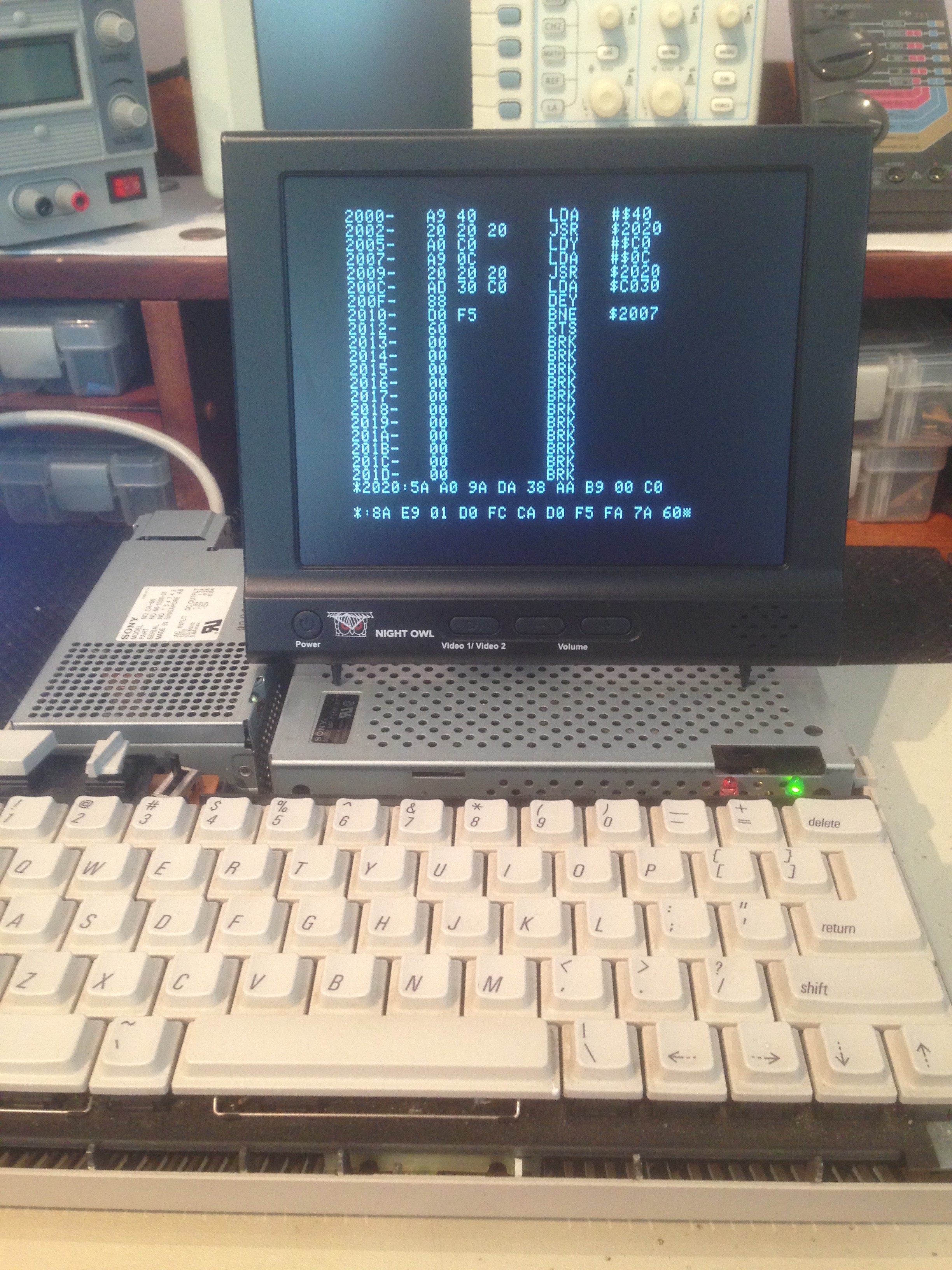
Okay, now that I’ve alienated half my readers, let’s start by experimenting with the IIc Plus’ beep code directly. We can do this by transcribing it from my dumped ROM into memory on the IIc Plus:
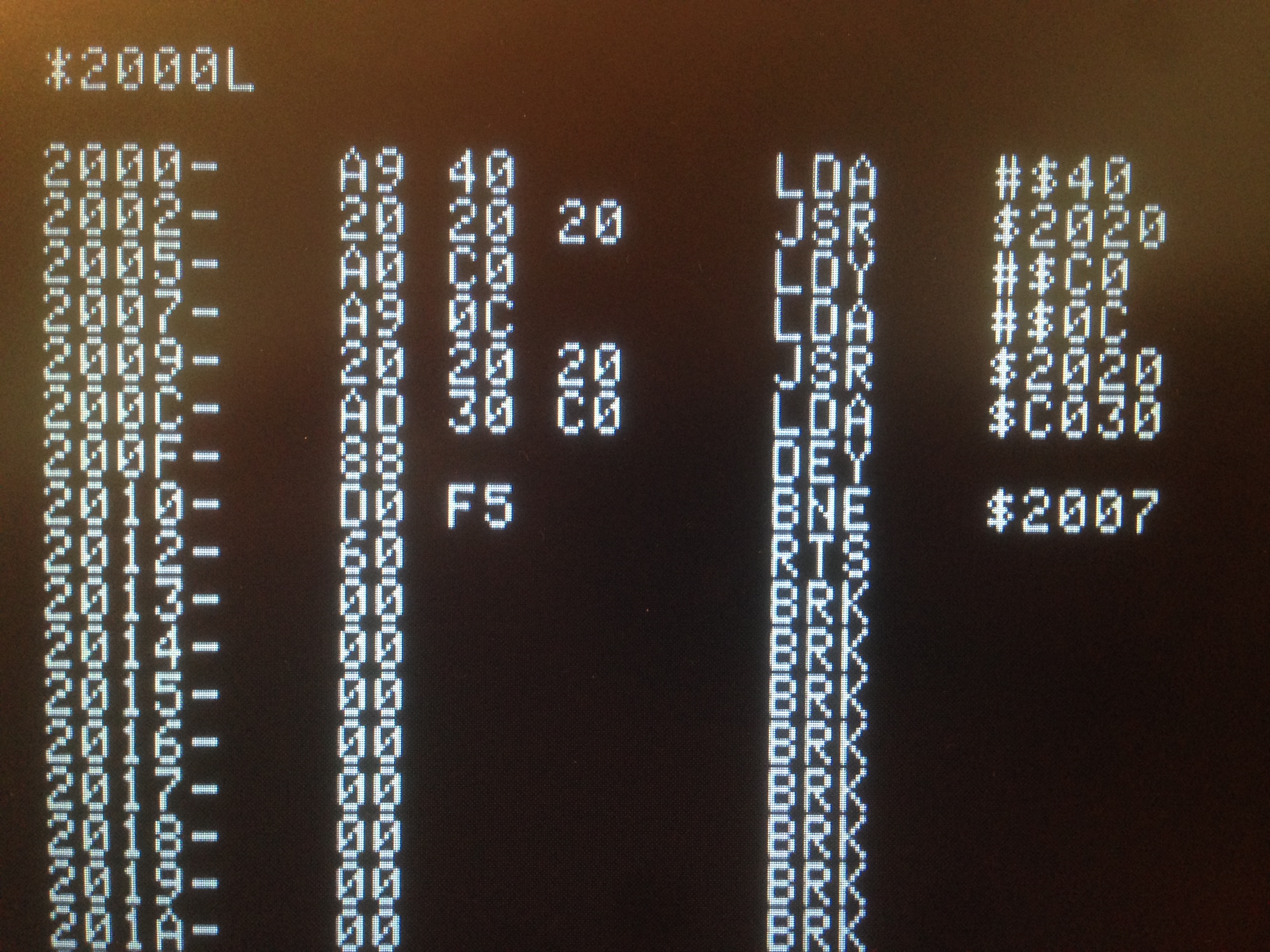
One thing to note here is the LDA #$0C instruction. This is setting the tone of the beep, so it may be enough to simply change this. With the code now in RAM, we can try “tuning” this. A single value change may solve our whole problem! In this video, I experiment with two values above and below $C0 for the tuning.
As you can (hopefully) hear there, this won’t work. A value of $0B is too high-pitched, and a value of $0C is too low-pitched. The correct tone is beyond the resolution of control we have with that one value. Time to go deeper.
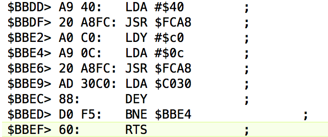
The obvious next step is to disassemble the IIc Plus’ beep code, and compare it to the IIc (the most similar model with the correct beep sound). We dumped the ROM previously, so let’s take a look. We know from the docs that the ROM entry point for the bell is $FBDD. This is $BBDD in physical address space, because as we learned last time, the IIc Plus swaps two ROM pages back and forth to double the amount of code.
Comparing to the source code listing for the older IIc ROM, we see:
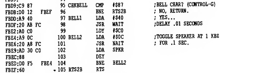
Interestingly, the actual beep code is the same on both machines. The difference must lie in the delay routine at $FCA8. This is officially known as ROM WAIT, and software is supposed to use it when consistent delays are needed. Remember, these machines don’t have real-time clocks, so counting time is actually pretty tricky. Up until the IIc Plus, this didn’t matter too much. All the Apple II machines ran at 1.023MHz, so you could just run a busy waiting loop in your code and know that it would take the same amount of time on everyone’s computer. The IIc Plus has the option to run at 4MHz, so that assumption is no longer valid. Presumably, Apple addressed this in the standard $FCA8 delay routine. Let’s find out.
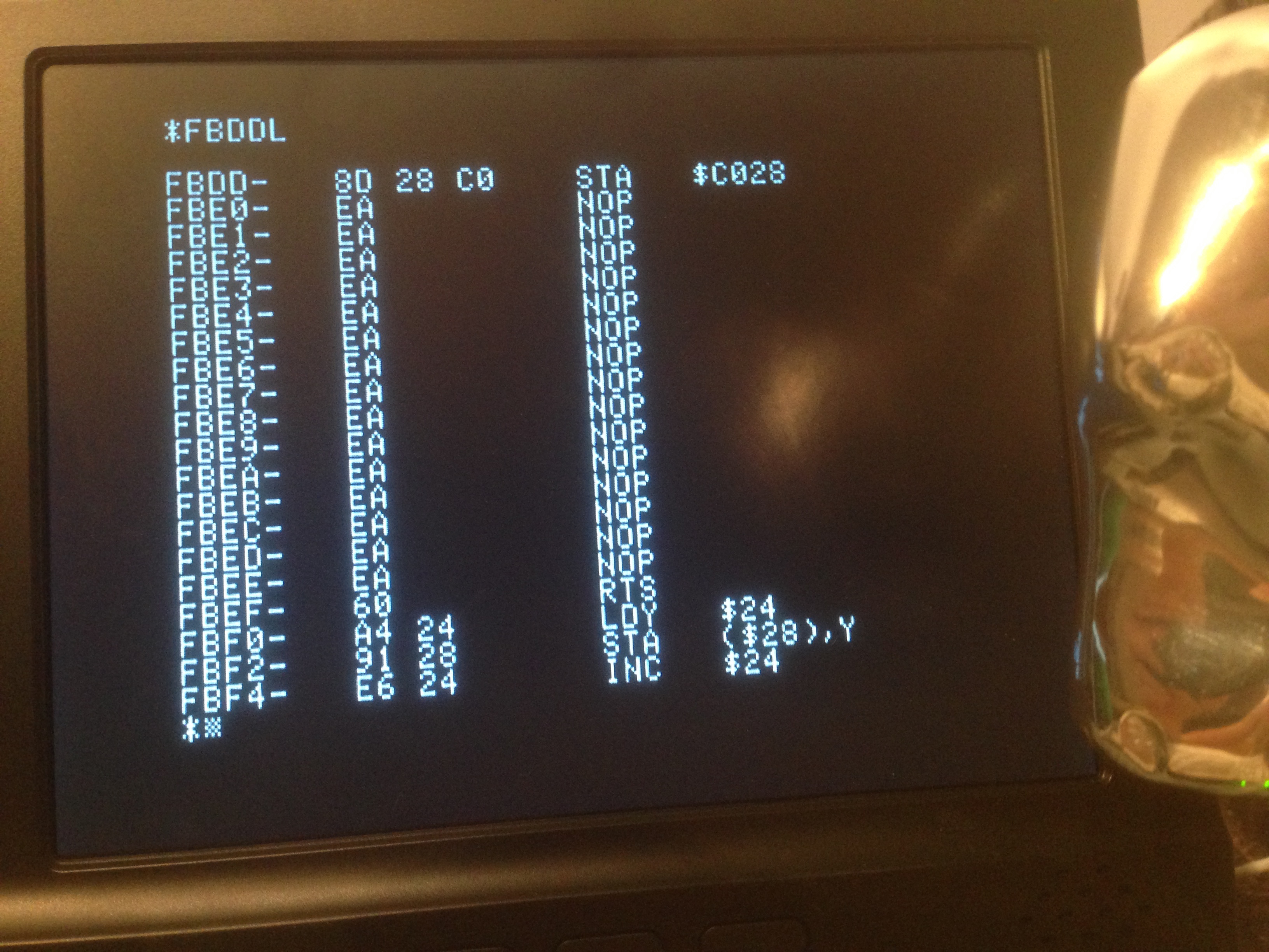
When we look at $FCA8 in the lower bank of ROM (the one normally switched in), we find only this:

As you can see, it’s just a stub. We learned last time that $C028 is the semi-documented soft switch for flipping ROM banks. The reason for the NOPs after that is not clear, but may have to do with how we get back from the other ROM page. Bank switching code can be very mind-bending. To paraphrase Back To The Future, you have to “think fourth dimensionally”. As soon as that switch is flipped, the code you see (the NOP chain) ceases to exist. It is replaced by whatever is in that same spot in the other bank, completely transparently to the CPU. It will immediately execute code 16k down from here instantaneously. It’s like a virtual branch. Neat!
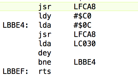
So, disassembling that upper bank portion of the ROM at the same address, here’s what we see.
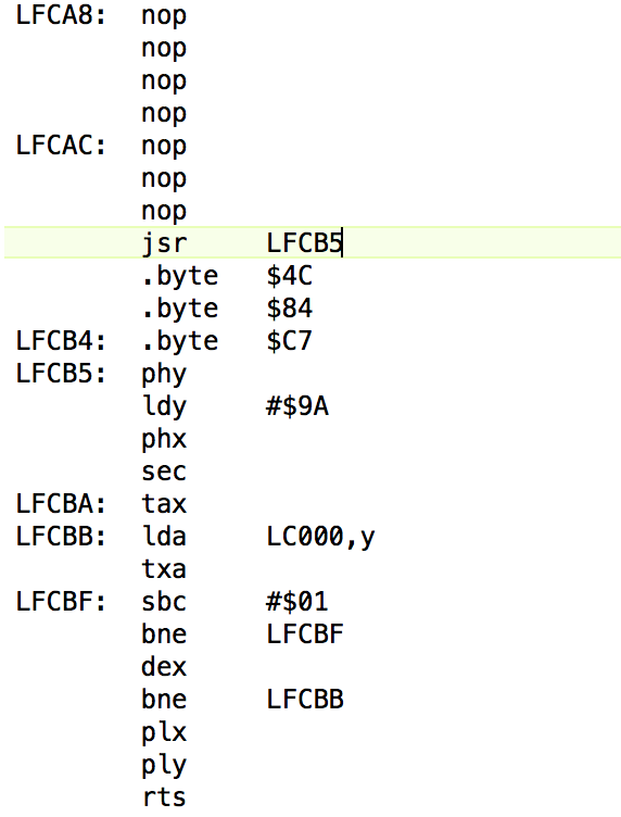
The code starts with more NOPs. This makes sense, because the first three bytes of that code “don’t exist”. The three byte instruction that flipped the bank and got us here occupies that space, so the program counter will be pointed at $FCAB when we get here. Think fourth-dimensionally! 1.21 gigawatts!
The next weird thing is, after a few NOPs, the code immediately does a Jump Subroutine to $FCB5. That seems odd now, but will make sense later. Note those three data bytes- they’re actually code, but the cc65 disassembler has become a bit confused there.
From $FCB5 onward, we’re doing the actual delay-loop code there. It’s simply a nested loop that counts down based on the accumulator. More on the algorithm later, but let’s sort out the flow first. At the end of the delay, we RTS. Where does that go? Well, back to those bytes that cc65 didn’t disassemble. Remember that weird 3-byte JSR we did to get here? We skipped code that does a JMP $C784. So we JSR, do the delay, then come back and jump to $C784. Why? Well $C784 contains this:
What’s really interesting is that this same code exists in the same place in both banks. This is used as a “get me back to the other bank” mini-subroutine that is safe to call from anywhere. That’s why the delay code uses a seemingly-pointless JSR over three bytes. We needed an extra frame on the stack so that we can use our own RTS to get back to the $C784 routine, which then does another RTS to get back to the original caller. This can be a bit confusing, but I’ll be laying it all out more clearly here in a second.
There’s a million-dollar question hiding in this delay code. It needs to behave the same way at both 1MHz, and 4MHz. How can it do that? The answer lies in this cryptic bit of code:
That code makes no sense at all, at first glance. We’re loading accumulator from something that isn’t a soft switch, and never using the value. What is $C09A, and what is that code doing there? Some poring over the documentation revealed this:

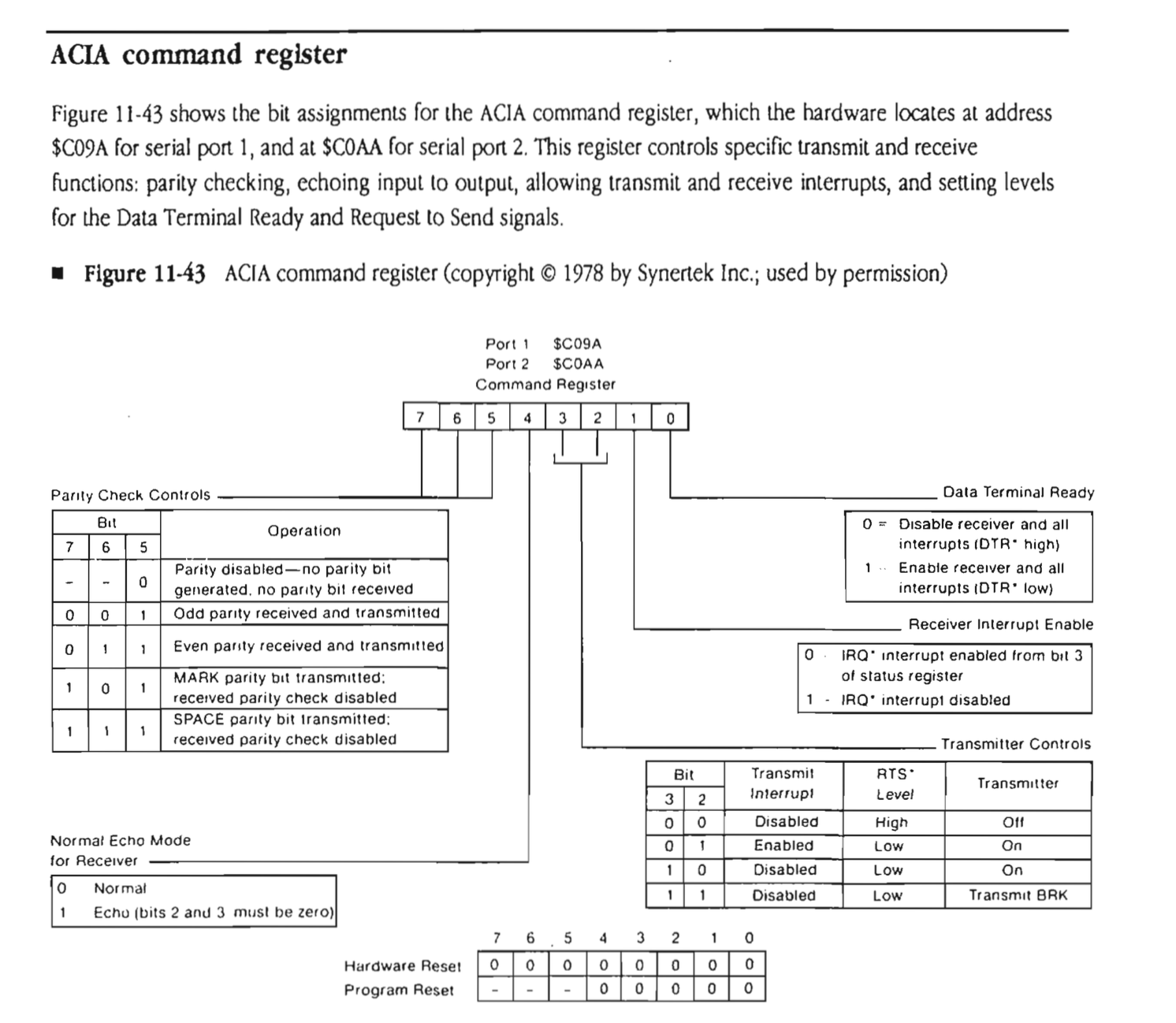
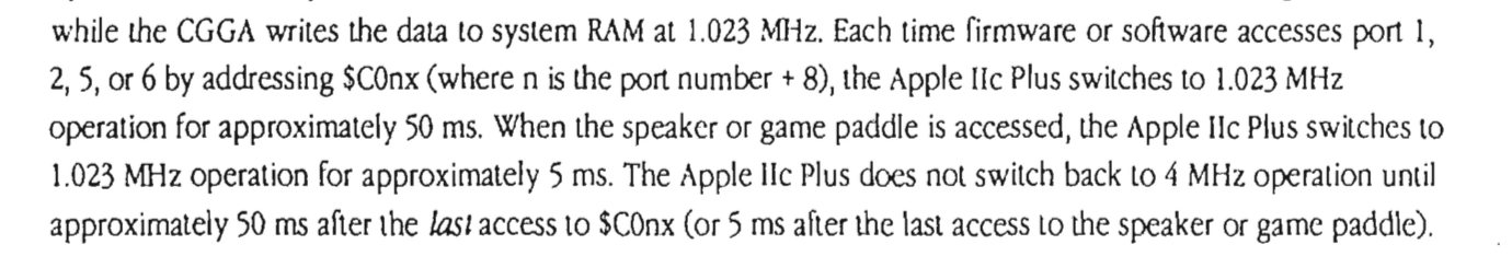
The answer to this mystery lies in how the IIc Plus accelerator works. It’s technology that Apple licensed from Zip Technologies to compete with the faster Laser 128 line of clones. It’s a combination of fast cache RAM, a 4MHz 65C02, and some clever circuitry. The latter is necessary because a lot of Apple II hardware is timing sensitive and must be run at 1MHz. Among that hardware is… you guessed it… the serial ports. So, that mysterious accessing of the status register serves only to trigger the custom accelerator circuitry that slows the machine down to 1MHz. In fact, the documentation states that the machine slows to 1MHz any time the serial hardware is touched, but automatically resumes 4MHz operation after 50ms. For that reason, the delay code touches that serial port register every time through the loop to make sure the machine stays at 1MHz for the entire time.
The big question is, how is this wait routine functionally different than the IIc? We know this is the source of the different beep, but why? The IIc’s delay loop is very simple.
Next to the code, I’ve listed the cycle counts for each instruction. The accumulator is the “duration” parameter on this function. Note that branches take one less cycle when the branch is not taken. That means the final iteration of each loop is slightly faster.
This is our baseline. We know this delay code gives the correct beep sound. There’s a 5 cycle inner loop, a 12 cycle outer loop, and 8 cycles of constant overhead. For A=1, this gives us 23 cycles at 1MHz, which is 22.4829μs of real time. The code isn’t linear, though. Because of the the types of branches and how the accumulator is reused, it’s actually a polynomial series. For A=5, we end up with:
5 + 24 + 9 + 3 + 19 + 9 + 3 + 14 + 9 + 3 + 9 + 9 + 3 + 4 + 8 + 6 = 137 cycles
Now let’s look at the IIc Plus version. This one is much more complex, because of all the bank jumping and such that we do. Here’s the entire process of a call to the delay routine, laid out linearly with cycle counts on everything.
As you can see, the IIc Plus version is madness. The core of the same polynomial series is still there, but because of all the extra hoops it has to jump through, it has to save and restore registers, incur more overhead in several places, and generally winds up with very different timing. I’ve annotated the source code above with the cycle timings, making particular note of the sections running at 4MHz. We can “normalize” all the code to 1MHz by dividing the high-speed cycle counts by 4. Only the pre-loop setup section runs at high speed. This gives us a 5 cycle inner loop, an 11 cycle outer loop, and 22 cycles of overhead. It’s similar, but not the same as the IIc’s code. I’ll save you the full polynomial expansion, but for A=1, we end up with 33.9154μs. That’s 11μs slower than the IIc’s routine for the same inputs, which explains our lower-pitched beep on the IIc Plus. That seems like a large difference at A=1, but the error bar approaches zero rapidly in longer delays. It’s actually pretty impressive how close they got the two delay routines, considering how different the code has to be.
So what can we do about this? It’s tempting to try and rewrite this delay routine to behave the same as the IIc version. However, this routine is used in many, many places in the hardware and software. I’m wary of messing with this and possibly introducing bugs in the floppy disk controller or something. Apple no doubt beta-tested the crap out of this code, and it works. All I want is to fix the beep, so a more surgical approach is the smart play here.
The next thing to try is to transcribe the IIc’s delay routine into memory and have our RAM-resident beep code use that. If we can replicate the correct beep sound “in the lab”, as it were, we can move it to ROM with confidence. Initially, I included the now-familiar LDA #$C09A code in my new delay loop, because we learned that will be needed to force the machine to 1MHz and make it behave as the IIc would. That’s when I learned something else interesting…
The good news is, this seemed to work just great. The weird news is, the forced-slowdown to 1MHz via the serial-port register trick seems to have no effect. The beep sounds correct either way. Wha? Here you can see me playing the beep a couple of times, both with and without the LDA $C09A:
I verified with a simple BASIC for loop that the machine was running at 4MHz (compared to Virtual II at 1MHz), so whats the deal? A bit of quality time with bad scans of 30yo documentation turned up the answer.
In hindsight, this is quite obvious. Since audio is entirely CPU-driven on the Apple II (simmer down Commodore and Atari people), the CPU speed has to be the same across the model line or audio code won’t sound right. What this means is that, in the case of the beep, the IIc Plus’ extra effort to force 1MHz in the delay loop is actually unnecessary. However, that delay code is used by many other systems not related to sound, so it makes sense. It’s a general purpose implementation. That’s good news for us, though, as we’ll see. Let’s do a final RAM-resident test against the target beep sound.
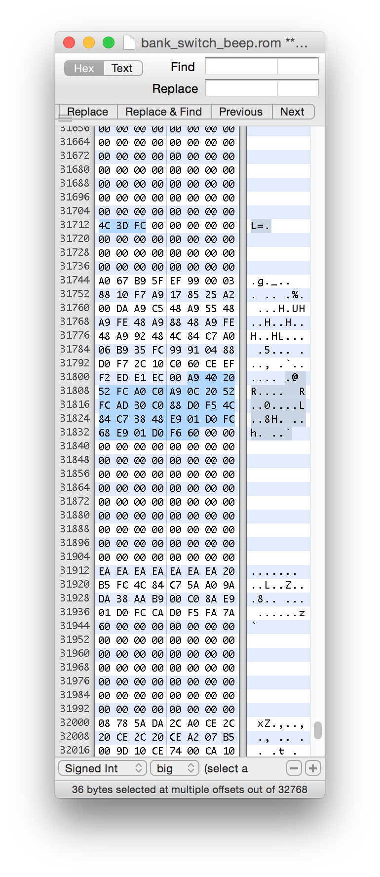
With all this in mind, we can proceed with modifying the ROM itself. As discussed, I’m going to write a second delay routine that is used only by the beep, and hide it in an unused corner of ROM. We can then alter the beep routine to JSR to our delay instead of the factory one. This turns out to be a bit easier said than done, however. There’s no free space in the “normal” ROM bank (which is, after all, why they needed a second one). We need to add our code to the auxiliary bank. We can’t JSR directly from the beep code to a delay in the other bank. We also can’t make the beep code any larger, because it’s packed in tight with all the code around it. The solution I opted for is to move the beep code and the delay into the other bank. I replace the original beep routine with a bank switch and some NOPs. For this to work however, remember we have to think fourth dimensionally. That means there needs to be empty space at the beep code’s location in the other bank. As soon as the beep code flips the bank, it’s going to be in trouble if we land in some other code.
Could we be that lucky?

Huzzah! There is a small empty space in the beep’s location in the other bank. Unfortunately, there’s only 32 bytes there, and we need 36 bytes for our combination beep/delay routine. Painful, but true. I spent some time trying to get four bytes out of the code, but couldn’t do it without altering the timing (which would defeat the whole purpose of this exercise). No doubt a better 6502 programmer could solve this, but none of them live in my house. Instead, I use the “beep hole” to jump to yet another hole in the auxiliary bank where my code will live. I then need to get back to the original bank and fall back into the original beep code, so that callers are none the wiser. Here’s my code to do that:
Note that to get back to the original beep code, I actually use the same trick the factory code did- I jump to $C784.
Okay, it’s acid-test time. Let’s burn this to a ROM, put it in the machine, and see what happens.
Lots of interesting things happening there. First, the machine started with the new and correct beep sound. Result! Next, you see some Xs spam on the screen because the bottom of the keyboard was grounding-out a bit on the case. What happens next is very interesting, though- after a standard “Syntax Error”, AppleSoft BASIC starts reporting a syntax error on everything. A few lines later, it crashes. Clearly we have some unintended side effects from our changes.
It took many hours of debugging, but I managed to iron everything out. The ROM code on the Apple II is very, very efficient on space. This is done by heavy factoring-out of shared elements. Completely unrelated code sections often jump into each other and back out to save a few bytes. Any code that can be shared, is shared. Memory was extremely precious back then, so a byte saved was money in the consumer’s pocket (or Apple’s, depending on your level of cynicism). There was a piece of the text renderer that shared the RTS at the end of the beep code, and I accidentally stepped on a null-terminator for a system string in my new code’s location. Another insidious bug I had was a JSR that was two bytes short, causing the program counter to jump into undefined opcodes. The CPU executed over this into the correct code without complaint, but doing so corrupted the status registers just enough to mess up AppleSoft and nothing else. All of this takes a very long time to figure out when you have to burn a ROM for every test. These bugs only manifest in the real ROM with the hardware page-flipping taking place. There’s no way to simulate that in RAM. To clarify this point, here’s my new beep code in ROM:
I’ve been waiting decades to use the word “Forsooth” in a sentence. It’s possible this entire blog was culminating on that moment. You’re welcome.
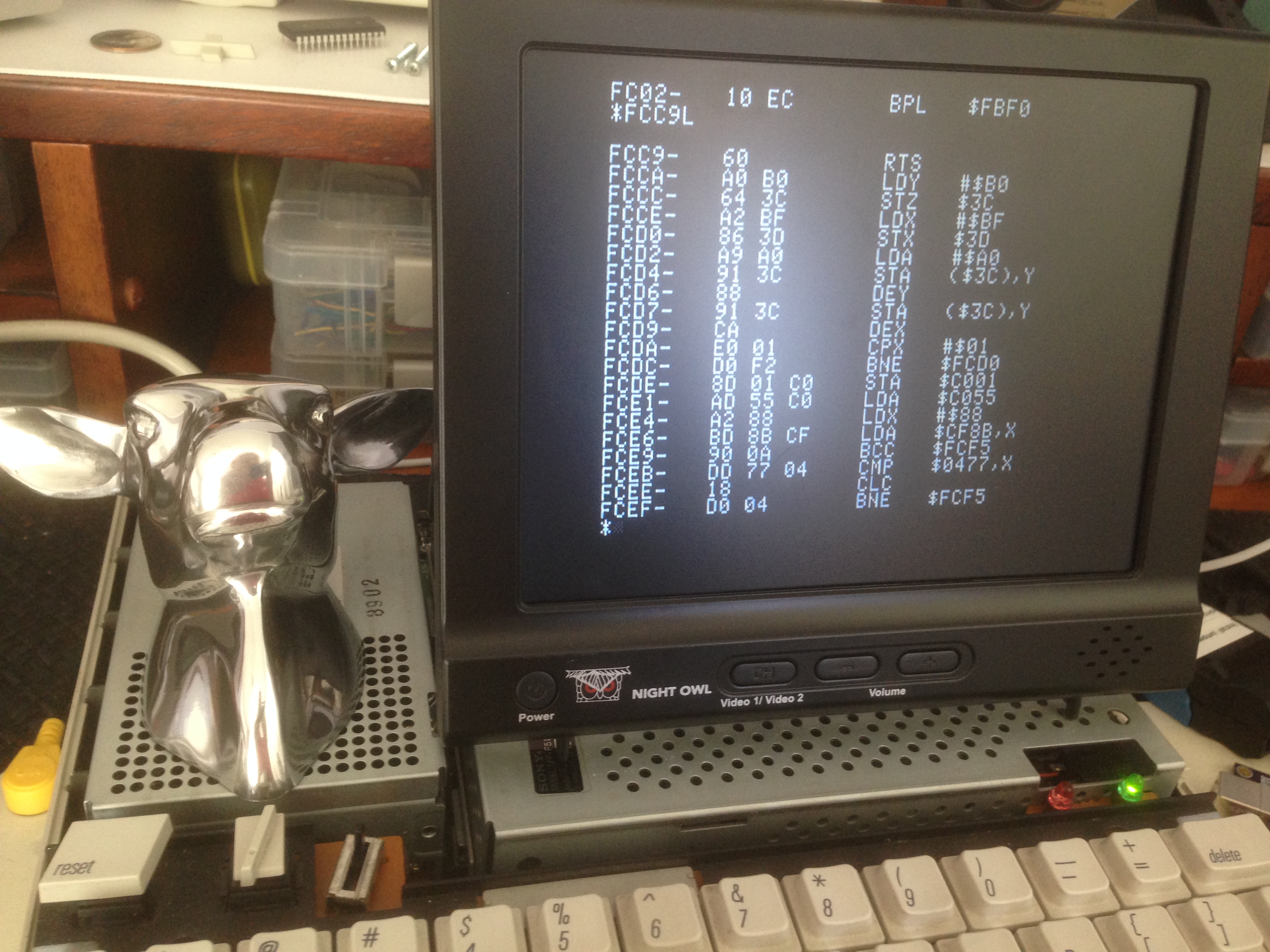
Just to prove my point even further, here’s what the factory beep code now looks like:
Here’s a final demo of everything in action. You can see the machine boots with the new beep, and responds with the new beep when executed directly in the monitor. You can also see the AppleSoft problems are fixed. Just to show off, I finish by listing the factory ROM entry point for the beep, showing that it’s now just a page flip.
There you have it! There is now one Apple IIc Plus in the world with a correct Apple II beep. Twenty or so people out there are super jazzed about this, and the other seven billion have no idea what the hell I just spent the last three weekends doing. Well, my mom thinks I’m cool.
I see a missed opportunity for an Inception joke in there.
You’re right…. ROMception is definitely what reading that IIc Plus code feels like.
As far as I’m concerned, the minimum target audience for a successful hack is one: the performer of said hack. That being said, I’ll count myself among that twenty or so people who are super jazzed. Very cool!
I concur. If the love of the task isn’t enough, you wouldn’t be doing it!
Brilliant breakdown/explanation of your hack. I picked up an old Apple IIc recently and thanks to this post, I can’t wait to get hacking on it. I have twin 6 year old girls and that Apple IIc is going to be their first machine.
BTW: *my* old Commodore 128 had a built-in machine language monitor/{dis}assembler, thank you very much. It also included a sprite editor in ROM. You’ve got one of those too, right? 😉
Sprite editor? Sure! Um… *cough*… it’s… uh… in the back somewhere I think.
From what I’ve heard, the C128 was a really cool machine. Definitely under-appreciated.
The IIc is a fantastic choice for your girls. I think it’s very valuable to see where computing comes from. They need to appreciate how much technology is really behind a simple tweet or snapchat.
Love your articles – write ups. I would truly like to get a copy of the burned ROMs (I think you’ve created.). If you haven’t burned “extra ROMs, and don’t intend to get into that business, I would like to know the equipment you use that I might update MY IIc+ ROMs and perhaps … address the desire to have a IIc+ read and write 1.44 MB floppys.
Thank you very much for all that YOU are doing!
Gary
Thanks, Gary! Unfortunately, I can’t legally distribute this code, because the unmodified portions are still owned by Apple and Microsoft. For some reason, they refuse to release 30yo 8-bit ROM code into the public domain.
However, if there’s enough interest, I may make a few of my ROM dump/burn tools available for purchase. If, after buying that, you managed to acquire this modified code somehow, well, I wouldn’t officially condone anything that might happen after that.
You can always distribute your changes as a binary diff (bdiff/xdelta/IPS/whatever).
Gently laughing out loud … Please consider me interested. Thank you again for what you do … ntm your quick reply. Wahoo! – Gary
Quinn, awesome post as always! Minor nit – near the top, you are describing the beep routine, and you say “One thing to note here is the LDY #$C0 instruction. This is setting the tone of the beep…”. I think you meant to say the “LDA #$0C” instruction. That LDY #$C0 just sets the duration of the beep. 🙂
Also, a question – was there any reason to replace the original beep code with NOP’s? Could you have just left all of the dead code there, except of course the STA $C028?
Keep up the great work!
Good catch- thanks for the correction!
The reason to NOP-out the old code was basically to prevent side effects or crashes if the PC ended up in there somehow. I learned The Hard Way™ that the ROM code jumps around internally in very hard-to-find ways, so it covers my bases in case I missed someone jumping in there. They will NOP their way down to the RTS and nothing should break.
Another reason for the NOPs I remember reading was that needed to keep as many entry points that were not documented but commonly used in software the same, so they need to keep the spacing of the ROM and thus all the entry points as close to the previous ROMs as possible as to keep compatibility. Compatibility of the ROMs is quite a dirty business, and it was cool to see how the original macintoshes handled it with TRAP patching on the 68k, but people still broke the rules sometimes there. Back in this day you had to break the rules to get anything done and there weren’t any anyways.
My first Apple II was a IIc Plus. So I never realized that it has a wrong kind of “beep” 🙂
Quinn, if you are going to do this kind of in-rom work more in the future, do yourself a favor and beg/borrow/steal/build an EPROM emulator for that system.
You may not be familiar with these beasts, but back in the day, we had a gizmo that plugged in place of a EPROM. Instead of a ROM, it had a RAM chip on it and a serial (or other) link to another computer. Under normal operation, the thing behaved more or less like a fast EPROM. But if you hold your target system in reset (to keep it from accessing the ROM), you can use the serial link to write your new program into the EPROM emulator in a few seconds, then let the target system run.
It’s obviously not going to hold memory across power loss, but the really fancy ones were setup so that when you started to access it from the control PC they’d automatically put the target into reset.
I just tried some google searches and everything I came up with is WAY too expensive/complicated or unsuitable. I’ll see if I can find any references around the office to the ones we had back in the mid-1990s – they were REALLY low-end examples of the type (just a small PCB with chips stacked on top and an RJ-11 on the top), but they worked great! I was using a set of 4 of them in my work at the time and boy did they speed EVERYTHING up.
I don’t think we still have them, though we do still have a TMS-34020 ICE, so who knows.
(NOTE: I’ve just realized that I used ‘back in the day’ in a way that makes me sound even older than my children make me feel. In fact my programming career started in the late 1990s, so I’m not THAT old. Yet.)
If I had needed to do much more than the work shown here, I would certainly come up with something more efficient to iterate with. I think that goes without saying.
A 34020 ICE!?! I’m guessing a smart person could probably write something that ran on Mortal Kombat hardware using that.
Yeah, we used to use a box called Romulator when we did this sort of thing back in the day at Apple.
Back in ’84 I had a between semester gig at a chip startup. They were just to the point of getting viable wafers and were intensely testing each chip in place before cutting. They had a test system running on Apple ][+ machines. One of the problems I was asked to solve was that the file size from a test run was greater than 256 sectors but the file system would display it as the value mod 256 (so 280 would show as 24). So I stepped through the display code using the monitor and discovered it wasn’t an oversight but a bug in the number-to-text algorithm. There was no room for the extra few bytes needed to fix it so I put fixed code at the end of the entire DOS code block and JSRed to it. Not as bad as dealing with bank switching but I did have to figure out how to save the modified version with the extra code on a floppy reliably and reproducibly.
Fun times.
Okay this begged me to comment.
I dug my Apple IIc out of its crude packaging ( between moving… storage… moving… flooding…… storage… moving…) to power everything up since it’s been sitting for like 5+? years. and in the process of doing this and attempting a serial link with my MBP I somehow stumbled onto your blog.
Oh what was I going to say.
( for some reason my text-to-speech software spit out “all over the NSA” instead of “was I going to say” hmmmmmmmmmmmmm? ).
a lot of this one went over my head, but 2 things are clear. 1. I have no programing knowledge and 2. I so totally want to do this to my…. oh wait I don’t need to, Can I do it anyway?
that beep is so totally weird, and I wonder why they didn’t just fix it originally?
and LOL “ROMception” THE NEW WORD of 2016, with a book in 2017, and a movie in 2018.
Thanks for this interesting adventure.
My first computer was a Formosa LM-2000. An Apple ][ clone. I wish I still had the macro-assembler I wrote for it (in basic). Your hacking brings back fond memories
Dunno if you’re familiar with http://www.folklore.org/. But if you’re not, you should be 🙂
it’s a collection of anecdotes from several developers at apple back around the development of the original Macintosh (and apple II) 🙂
I had a look and it’s an interesting site. More Mac than Apple][ unfortunately .
I am super-jazzed. I want to do this to my IIgs, which also has a totally wrong beep.
Hey, I know you. 😉
I have mixed feelings about the IIgs beep. I like the melody of it, and how it leverages the more advanced sound. However, it’s so sloooow. I always feel like I’m waiting for it to finish.
The IIgs “beep” always sounded like an unpleasant “honk” to me. Not a fan.
But you could go into the Control Panel and change the pitch of the beep. I always cranked mine to the highest pitch – it seemed the most pleasing to me.
The IIc Plus had no control panel or configuration options like that. I believe you might be thinking of the IIgs, which is a much more complex and sophisticated 16-bit machine.
I wonder why they didn’t delay the bank switch for 3 memory accesses. That way you could execute a JMP from the original bank after the STA and have the switch occur just before it starts to execute at the new address. Result: far fewer headaches.
Did you notice the two typos in the sad old scan? WAIT at FCAB and NAIT at FCA8. Looks like OCR work to me.
I did notice that, yah. That’s interesting because it suggests the document was scanned, OCRed, printed, then scanned again into an image-based PDF. Who knows how we got to this point. 🙂
well, one comment says .01 second and the other .1. So wait and nait might actually be different existing functions at different addresses doing different things. But it needs another source to verify that (since I’m not familiar with Apple ROMs at all).
And who says you’re not an excellent 6502 programmer? I’ll say you are, and swear on a stack of databooks that you are.
That is a truly amazing job you did for the machine. I wonder if it appreciates it? I know we all who got our start on that fellow’s family members certainly do.
There’s no such thing as a 6502 programmer who’s NOT excellent. You HAVE to be excellent to coax useful software from that godforsaken, malnourished architecture.
And masochistic, too.
Awesome article, really enjoyed this trip down the Apple ROM rabbit hole!