For once, wishing a computer was slower.
A little while ago, I went on a semi-epic (sempic?) quest to fix the beep in my Apple IIc Plus. I considered that an outright bug. Well, an abomination against civilized humanity really, but “bug” will do as a technical characterization of the beep problem. But I’m not done yet.
The next change I want to make is with regards to the behavior of the clock speed. The IIc Plus has a unique feature in the 8-bit Apple II line- it has the ability to run at both 4Mhz and the usual 1.023MHz. Every Apple II since 1977 has run at the latter speed, until this machine. This makes perfect sense in 1987, because by then you’re probably buying a computer for real work, much like users today. If you’re running any of the excellent productivity packages, such as AppleWorks, Multiscribe, GEOS, or PFS, you definitely want a machine that is as snappy as possible. To that end, the Apple IIc Plus defaults to 4MHz on every boot up. To run at the old 1MHz speed, you have to hold ESC while rebooting or resetting. Every. Freaking. Time.
What’s the big deal? More emm aitch zees is always better, right? Well, not quite. The Apple II is interestingly primitive. It has no clock, no system timers, no high frequency tick counters, no interrupts, no active vertical blank signal; in other words, nothing that can be used for time reference. Time can only be measured by hand-counting CPU clock cycles. If you want to wait for 1ms to pass, you literally have to write a busy-wait loop that burns up ~1000 clock cycles (roughly 400 opcodes through the pipe, depending on how you write the loop). This very primitive timing mechanism means trouble for games. Games need to control all aspects of their timing in order for animation, sound, and gameplay to be right. There’s no reasonable way to write a game that runs independently of CPU clock speed without an independent time base. Such technological advances would not come to the Apple II line until the IIgs. Of course, other contemporaries such as the Commodore and Atari 8-bits had all manner of clever and convenient interrupt sources and other timing mechanisms. They came along well after the Apple II, however, and by then the technical limitations of Wozniak’s platform were too entrenched to change. At 4MHz, virtually every Apple II game is unplayable. This wasn’t a huge problem at the time though, because the IIc Plus could still be slowed down with ESC when booting a game. Interestingly, the Laser 128EX and 128EX/2 clone machines also had an accelerator, but they defaulted to 1MHz. They even had three speeds, instead of just two. One of many ways that V-Tech’s clones were giving Apple a real run for their money. Anyways, one particular consequence of 4MHz is that it messes up the custom disk I/O routines in some copy protection schemes. The perfectly legal copy of Infiltrator II that I demoed recently, for example, will not even boot at 4Mhz. See? Even in 1987, DRM was ruining the day of perfectly law-abiding media consumers.
Now that these computers are retrocomputers, the usage patterns have changed. What was supremely convenient is now supremely annoying. I have a modern computer for productivity, and emulators for programming, so my Real McCoy hardware is for playing games 99% of the time. I want it to default to 1MHz. Can we make it do that? Let’s find out.
The first step is to figure out where the accelerator is being set up on boot. Conveniently, the accelerator does have a firmware interface, and it’s (mostly) documented in the Apple IIc Technical Reference Manual 2nd Edition. Technically, we only have firmware access to the Cache Control Glue Array (CGGA) which is a custom piece of silicon that interfaces the faster clock to the various parts of the IIc Plus that need to run at different speeds. The serial ports and disk controller, for example still must run at 1MHz, while code, graphics, etc can be sped up. The CGGA conducts this witchcraft. Here’s the juicy bit of the sparse documentation on directing this beast:
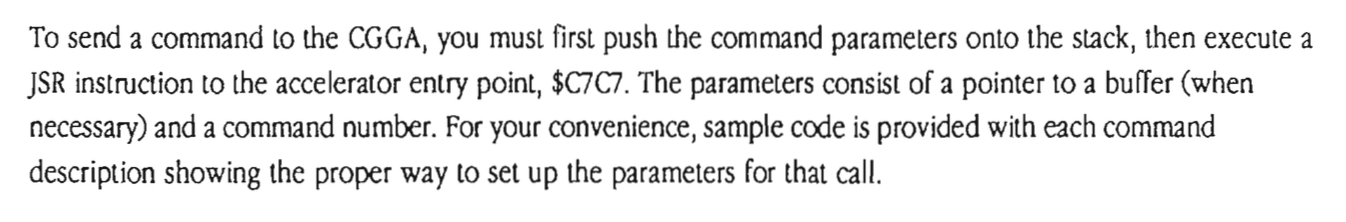
It’s all about that $C7C7 access point (no treble). The documentation lists command words for enabling and disabling the accelerator, so hopefully we can find where the ROM is turning it on. Since we know from last time that the ROM is bank-switched, the access point may also be at $87C7. A while back I dumped the ROM and disassembled it, so let’s take a look.
Interestingly, there’s only a single call to that entry point in the entire ROM.
This follows the calling convention spelled out in the Technical Reference Manual (pushing a command word to the stack, then calling $C7C7). The interesting thing here is that the command word of $00 is undocumented. This must be some sort of initialization routine. Can we confirm this with another line of evidence? This block of code at $BD02 looks like a subroutine, because of the RTS (Return from subroutine) opcode at the end. Who calls this?
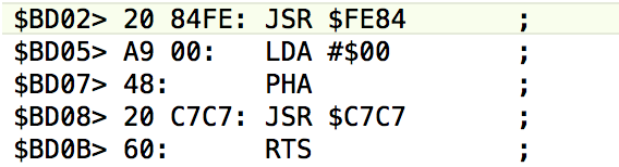
Nobody calls $BD02 directly, however remember this code is bank-switched. There’s no way to know which half of the ROM code is switched in at a given moment by static analysis of the code (unless we traced it by hand from the verrry beginning, knowing the initial state). As such, we need to trace all possibilities of both banks on every branch and decide which is most likely. You might call it Schrödinger’s Code. It means keeping a lot in your head as you’re tracing this stuff. I’ve done the heavy lifting for you, and found this very interesting piece of code that jumps to $BD02 (actually $FD02, because of the bank switch)
What is supremely interesting about this calling snippet is its location: $BA62. If we assume it’s bank-switched, then it’s really at $FA62. What’s $FA62? Well, lookee here at the ROM entry point documentation:

Yahtzee. I think we can be very confident that the original call to $C7C7 that we found above is the accelerator’s boot-up initialization. The bad news is, it’s the only reference to the accelerator in the entire ROM image. I was really hoping to find somewhere that the ROM was checking the Esc key and turning on/off the accelerator in response. However, since there is only a call to (presumably) an initialization routine, it seems like the CGGA checks the state of Esc key directly in hardware as part of initializing the accelerator. That means that if we make it default to 1MHz, we need some other way to choose 4MHz.
Here’s a neat idea- the Apple IIc Plus has a keyboard selector switch on top. This is used to choose between Qwerty and Dvorak keyboards. This was a bizarre idea even at the time, since nobody besides that one annoying friend we all have uses a Dvorak keyboard. Dvorak is the CrossFit of keyboard layouts. You know exactly who in your life uses it, because they won’t shut up about it. Now, I would happily use this keyboard button as a speed selector, if its state is accessible from the ROM. A survey of the documentation seems to indicate no way to check it, however, so a trip to the schematics is in order.
So much for that idea. Well, we should be able to do something similar to what the original ROM did, but checking Esc ourselves for the opposite reason after the accelerator is initialized. First things first- let’s see if accelerator control works the way the documentation says it should. Never assume documentation is correct.
The docs say that the accelerator has an unlock/modify/lock cycle, with commands for each. Each command is issued by pushing a command value on the stack, then calling $C7C7. There are also more advanced commands for modifying the state register of the CGGA, which allows you to control the influence of the accelerator on the various slots and such. Amusingly, the documentation lists the changes you can make to each slot then and proceeds to say the slot will stop working if you touch those settings in any way. It begs the question why such support even exists if it can’t ever work, but here we are.
Anyways, I hand-assembled a quick routine to disable the accelerator, and entered it at $300 in memory using the ROM monitor. The Apple II has a nice little memory hole at $300 where you can put quick-and-dirty routines like this.
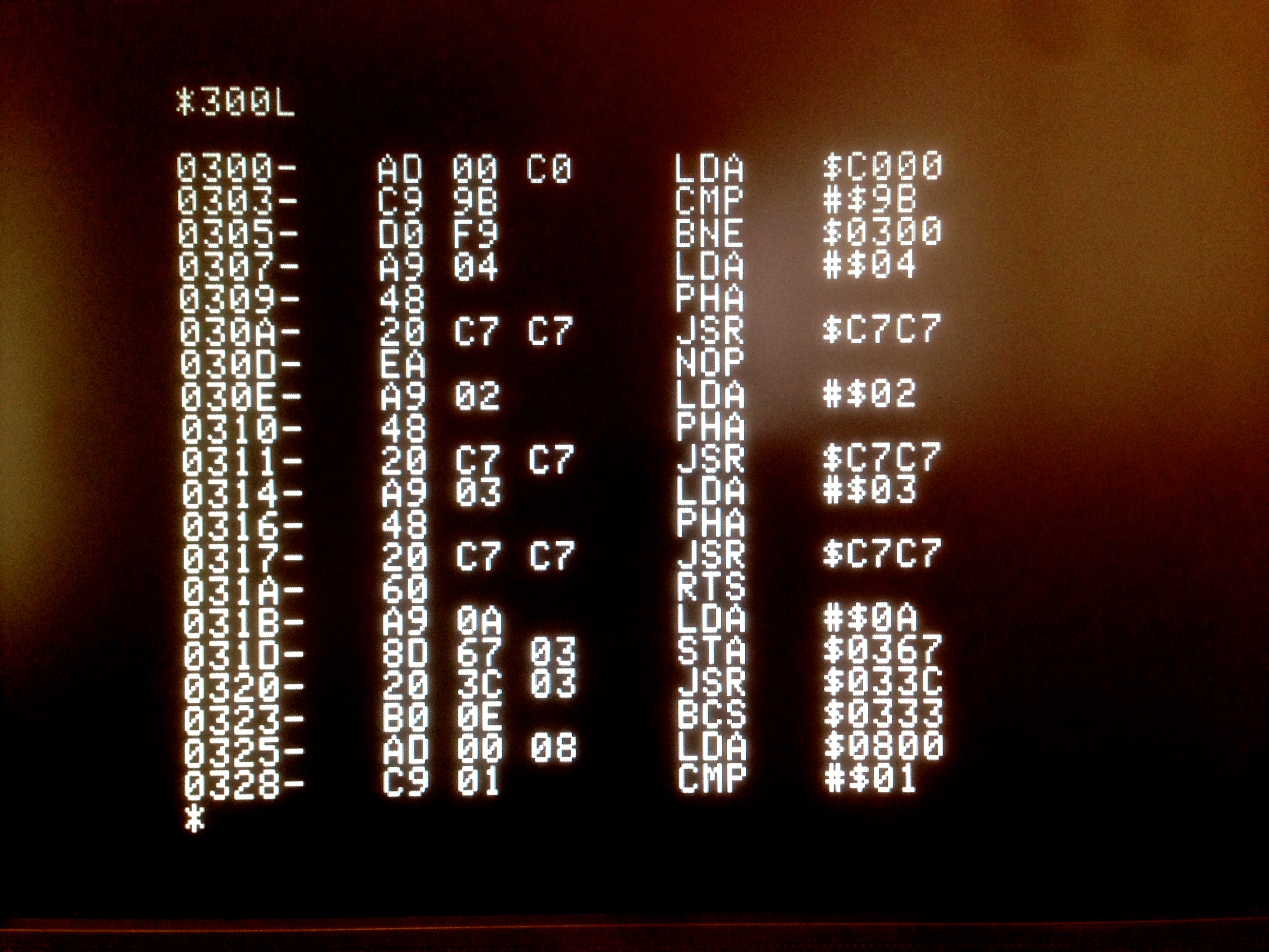
I then wrote a quick BASIC loop to count to 8000. This takes about 10 seconds at 1MHz, and about 3 seconds at 4MHz. From BASIC, I can do a CALL 768 to invoke my little blob of code to disable the accelerator, and hence know if the machine is really running slower. Indeed it did! So, I have verified that I can control the accelerator as indicated in the documentation. Now the test is whether I can do it from ROM at startup!
The next step is to find somewhere in ROM to place my routine so it can be patched in to the boot sequence. Similar to my beep fix, this means using the auxiliary ROM bank, because no appreciable free space exists in the main bank. I needed to find an unused hole in memory that exists in both banks so I could jump there, switch banks, then run my new code.
Remarkably, I found what seemed to be the perfect thing- a small space in the main bank to use for my switch, then a large space in the aux bank to put my routine. The patch consists of three parts- a stub to switch banks, my main routine, and patching the system init to call my routine. Since I have to replace a piece of the system init to do this, my routine also calls the replaced routines.
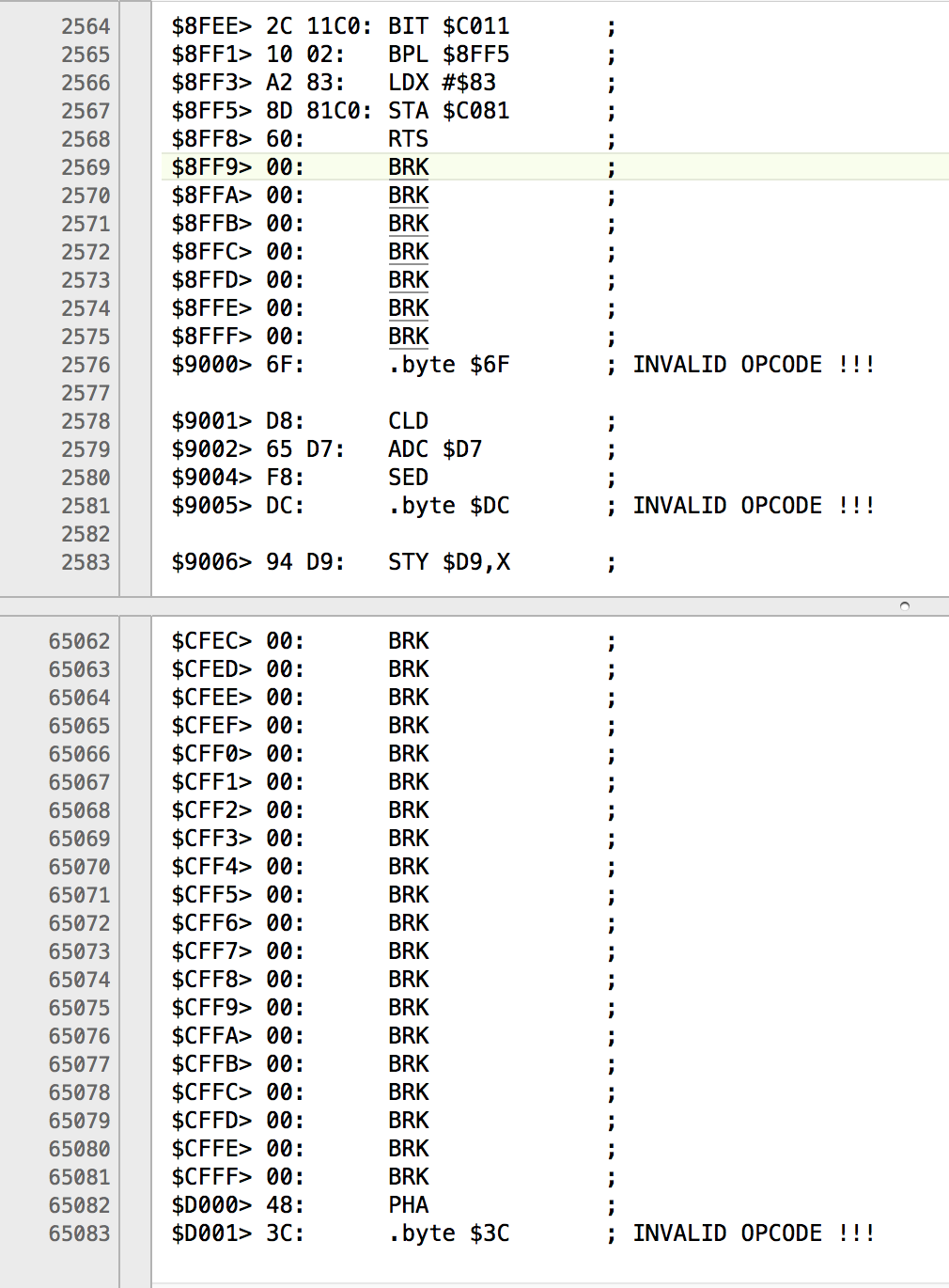
The factory init routine is then patched to call me at $8FF9 (actually $CFF9, since we’re in the lower ROM bank). I applied this patch to a copy of the existing ROM, and flashed a new EEPROM. I installed it in the IIc Plus, and it worked great! Except for the part where it crashes instantly 100% of the time. A romantic evening in front of the fire with the documentation revealed my error- my patched initialization routine lives in the auxiliary (upper) ROM bank, because that’s the only place there is room. However, the accelerator entry point can only be used when the main ROM bank is switched in. The documentation states the machine will crash otherwise. I can confirm this is the case.
Back to the drawing board. I need space to put an additional 30 byte init routine of my own nefarious design, but it must be run with main ROM switched in, and main ROM has no free space in it. Now what?
After some long walks in the rain and some quality Canadian rye (thanks mom), I had a lateral thinking moment- the answer of course is RAM. If I copy my code to RAM, I can switch main ROM back in, and run my code from RAM. Huzzah! I modified my routine to copy itself to RAM and switch the ROM bank before executing. My “little” patch is getting quite long now, but I found a hole that is plenty big in between the diagnostics and 3.5″ floppy disk driver (or something… I dunno, there’s a lot of freaking code in here). Here’s an alternate version of the previous patch, which copies the core functionality into RAM first, and executes from there, then jumps back to lower bank ROM.
Pretty clever, right? Well, except for the part where it doesn’t work at all.
At this point, my approach seems sound, so we need to debug the code itself. This code is executing incredibly early in the boot process (only a few dozen instructions after the 6502 itself has started fetching), so any kind of debugging output is impossible. We need to do this by static code analysis (a fancy phrase that means, “read it over and over until you find something wrong”). The approach laid out above has a lot of assumptions in it, so I proceeded to test the validity of them one by one. These assumptions include but are not limited to:
- That we can patch out the JSR $F2BF at all. Yep- I replaced it with the tiniest possible patch of one NOP, followed by a call to $F2BF thus returning to the original init. This worked.
- That we can jump away into the upper part of the memory mapped I/O page to execute code at this point in the boot. The place in $CFxx where I put part of my patch is technically reserved for slots to use, but I only need it for a moment. This worked- I jumped out to this area, executed some NOPs, and jumped back (or so I thought- more on this in a minute).
- That we can switch ROM banks and execute code during this init process. I wrote the smallest patch I could that switched ROM banks back and forth. I had to overwrite some part of (I think) AppleSoft BASIC to test this, but that didn’t matter. Here’s where the party ended. I did several versions of this test, trying to get the code to simply jump into the other bank and back, then resume booting. This shouldn’t be difficult, as it is a technique I mastered with my beep fix. However, the machine refused to boot if I touched that bank switch at any point. There may be some deeply esoteric reason why you can’t switch ROM banks this early, but I couldn’t find any documented reason for it.
So now what? Well, as I said, debugging is all about challenging your assumptions. I had noticed that my EEPROMs were getting slower and slower to write to. These things wear out from being written to, and I’ve been doing a lot of iterations. As a test, I flashed the original IIc Plus ROM to it, and tried to boot that. No bueno. This EEPROM was dead. That also invalidates the last several tests I did, because the EEPROM probably wasn’t written properly. Every hard problem has some backtracking, and this is what it looks like. Unfortunately, after getting a new EEPROM and re-running my tests of assumption #3 above, it became clear that it really is a showstopper. The ROM bank apparently can not be switched at this time, even if it’s switched right back again. There must be something fundamental in the hardware implementation of the MMU going on. Even worse, it turns out assumption #2 might be sketchy as well. The areas that I thought I could run code from turned out not to be executing my code at all. The machine booted, but my code wasn’t being invoked, despite apparently being in the code path of the boot. Very strange.
It was time to get crazy. Remember that mysterious Command $00 that is issued to the accelerator in the original boot sequence? What happens if we just NOP that out? I tried that, and the machine becomes locked at 4MHz, and the ESC-to-slow-down mechanism is disabled. That’s educational, actually. It means that undocumented Command $00 is the ESC-checker, and it also means the ESC is physically being checked in hardware by the CGGA. So much for that easy out.
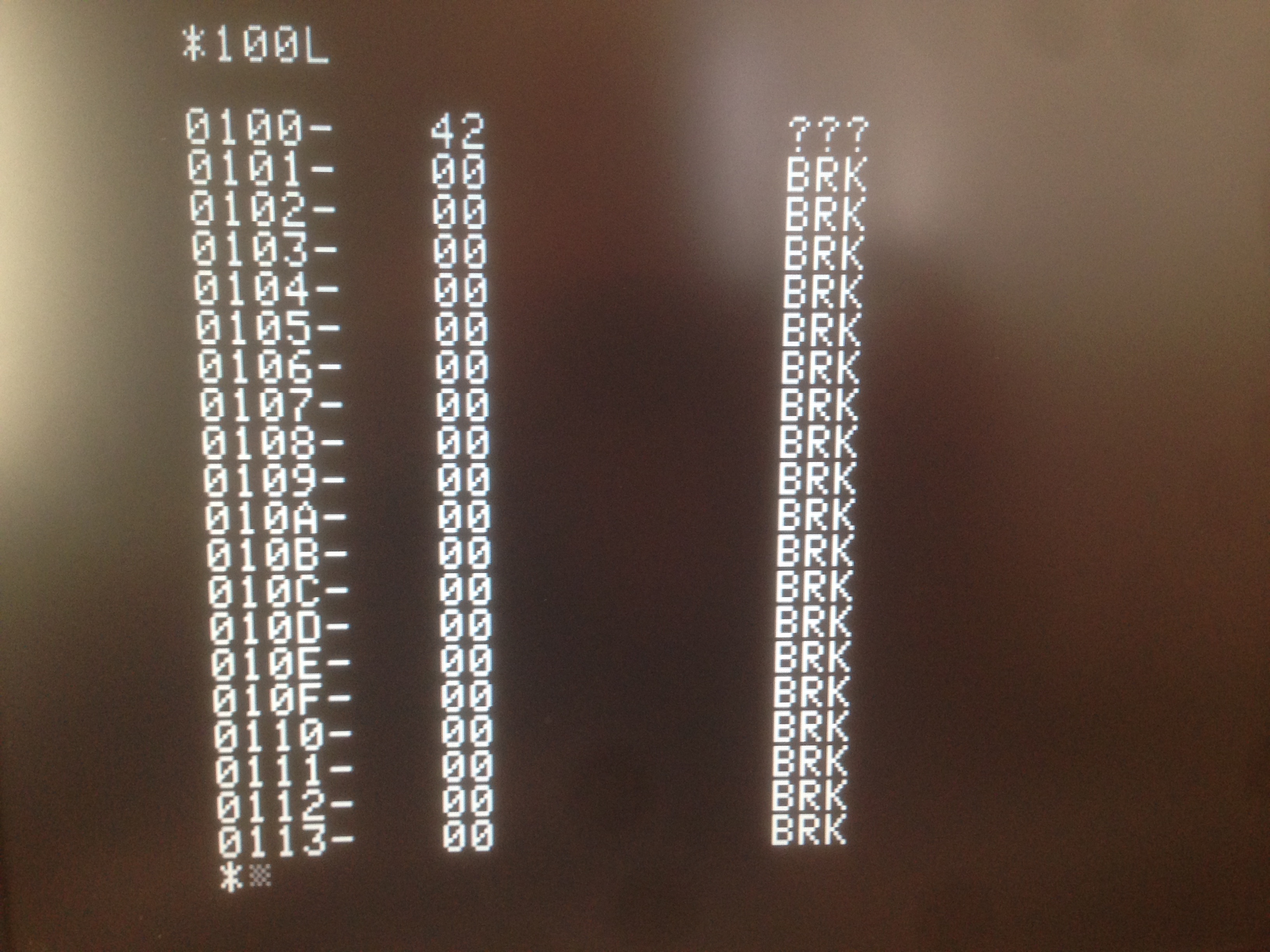
Back to my EEPROMs. I got some fresh ones, and started my debugging process over again. Debugging any complex system is about knowing your outputs and making rational use of them. In this case, because we’re so early in the boot process, the only output we have is “does the machine boot or not”. Still, we can use that. As I’m tracing through the boot process trying to reverse engineer it, I can put BRK instructions (opcode $00 on the 6502) in to form and test hypotheses of where the code is being executed at each part in the process. If I put a $00 in somewhere, and the machine locks up on boot, then remove it and the machine boots normally (without changing anything else) then I know the machine is doing what I think it is. This is a critical technique, because the IIc Plus boot process is obscenely complicated. It’s 32k of hand-written assembly, with a lot of bank switching and bouncing around off jump tables and such. Just finding somewhere reasonable to splice in my routine was a big challenge.
At this point I was stuck, because I couldn’t find anywhere to put my code that would work. As I’ve said, the IIc Plus does a lot of bank switching and messing with ROM and RAM overlays during boot. There are a lot of MMU-related soft switches being flipped that are simply listed as “reserved” in the documentation. Who knows what they are doing. The bottom line is that every area I tried to stash my code, it was ignored. Presumably because the machine had swapped in some piece of the language card or other mysterious ROM area at the time. Other areas simply crash when trying to run code (even NOPs) from them, for unknown reasons (probably related to a special state of the MMU or CGGA at the time). Even worse, I had exhausted all the places where there was a shared empty space between the two ROM banks. Remember that I needed to jump from one bank to the other, because only the upper bank has room for my new code.
Solving hard problems is a series of lateral thinking (or “Eureka”) moments, with a lot of hard work in between. The idea to run my init code from RAM is a good example. At this point, I had another (much needed) Eureka moment. I was out of ideas for how to fit my code into ROM, so I was just idly tracing through the boot process from the very first line of code, waiting for inspiration. It’s complex and convoluted, but you can trace through the boot process very carefully starting from the 6502’s first access of the reset vector. Around the half-way point, the code jumps into the other bank, where the 3.5″ disk driver lives, as well as some text window initialization goo. Suddenly it hit me- let the boot process do the bank switch for me, and do my business while we’re in there! It doesn’t matter when my code executes, so long as it is after the accelerator is initialized. Once I was on this road, I starting making forward progress again. I still needed a place to run my code from, but I had a sure-fire way to get safely into the other bank.
It was still a long battle of experimenting with different areas of the upper ROM bank, trying to find a spot that the machine would let me execute code from, and didn’t get overlaid by other ROM, BASIC, the CGGA, the MMU or other mysterious undocumented things. Eventually it dawned on me that I already knew an area of upper ROM where it was safe to execute my code from- I had found it while working on the new beep code. That area still had enough room left over for this hack to be squeezed in along-side. I now understood that I had gotten incredibly lucky with that first ROM hack. The first place I had tried to stash my code had worked. I now know that the IIc Plus does many tricky things with undocumented soft switches during boot up that shuffle RAM and ROM around in ways that are impossible to discern without a logic analyzer, a lot of free time, and prescription medication of some sort.
The last piece of the puzzle was how to get the accelerator to switch modes when I wanted it. I didn’t just want to disable it completely, though I now had the tools to do so. Ideally, I wanted to reverse the meaning of the Esc key. In other words, the machine would boot into 1MHz, unless you hold down Esc, in which case it would boot into 4MHz. This is the opposite of how it currently works. I figured I could simply check the Esc myself after the accelerator had done its initialization, and disable the accelerator if needed (Esc up), or leave it alone (Esc down). This turned out not to work, however. It seems that we’re so early in the boot process that the keyboard buffer isn’t working yet, so normal keys can’t be checked from software. This might be part of why the CGGA does this check directly in hardware, and why I didn’t find the ROM code that I expected to for this.
However, we have one last trick up our sleeves. The Apple II has two modifier keys, called Open-Apple and Closed-Apple (later renamed Open-Apple and Option). These ultimately became Command and Option on Macs. On the Apple II, these are not implemented as keys, however. They are actually wired to the joystick buttons, and are connected directly to the game controller logic on the motherboard, completely bypassing the keyboard encoder and buffer. These modifier keys each pull a signal low directly in a register when pushed. So, I changed my code to use the Option key instead of Esc, and it worked! There’s one slight complication- the Option key is also used as part of starting the self-diagnostic. If you soft boot with Open-Apple, Option, Control, and Reset, the machine runs a long series of self tests. This means with my new setup, you can’t change the speed to 4MHz via warm-restart (because it triggers the self-test instead). However, you can do it at power-on, or via soft-reset. Any reset scenario where Option can be down without Open-Apple will work. This is a small price to pay to have the accelerator behave in a way that makes much more sense for the way retro enthusiasts use these machines (aka more playing games, less balancing your chequebook).
Here’s the final sequence that I injected into the boot process, in chronological order:
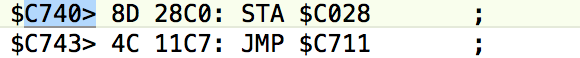
As discussed, I patch the boot to jump into my routine, which copies the meat of itself into RAM at $6000. This is a general purpose area that survives reboots, which made debugging this part of the process much easier. It then jumps into RAM, where it is now safe to switch lower ROM back in, check the keyboard & talk to the accelerator, switch upper ROM back, then jump back to where we left off in the boot. We’ve reversed the default accelerator state, and the system is none the wiser.
The actual binary patch applied to the ROM ends up being pretty simple in the final analysis.
Here’s a demo of the new code. I power up the machine normally, then run a ~10 second BASIC program to show that it is indeed running at 1MHz. Then I do a soft-reset with the Option key held, and run the same program again. You can see it execute in ~3 seconds, proving that we’re now switched to 4MHz.
This was one of the more difficult hacks I’ve done in a while. Several Saturdays were spent just making small changes and testing them, probing and tracing the boot to see how it worked and where I could sneak my code in. There was a point where I genuinely started to think this couldn’t be done. You just have to persevere through these moments and keep plugging away, even when it feels like no progress is being made! I actually burned through three EEPROMs while reverse engineering this machine’s boot. As I mentioned earlier, they get slower and slower to write as they “age”. In the interest of time, I would toss them when they got up to about 200ms per block. At that point it takes about 6 minutes to write the whole chip, which is a pretty terrible iteration time when you’re debugging by binary search and process of elimination!
Finally, I’m no longer envious of all the cool kids on the block, with their computers that are four times slower than mine! What a glorious time to be alive.
This is so fantastic. +1000 internets!
What an adventure, what a story, and what a hack — AGAIN!
A brilliant endeavor of clever engineering and determined perseverance. Thank you for sharing it, and congratulation on dragging your //c+ kicking and screaming back into the late 1970s!
Very enjoyable. So, storing to $C028 switches between main and aux ROM? That is, if you’re currently in main then it switches to aux, vs if you’re currently in aux it switches to main?
Yes, that’s correct. I determined this during my Beep Fix, previously. Reading that first admittedly provides some needed context to this post. What I learned this time is that there are additional soft switches doing unknown things with addressing space during boot. They are listed in the docs as “reserved on the IIc Plus”. I believe they are smaller memory overlays- perhaps within ROM or from other chips such as the CGGA. My evidence for this is that I found multiple spaces in the ROM that appear to be in the execution path of the boot code, but changes made to the area are ignored, even when filled with zeroes. Things that should crash but somehow don’t, despite being jumped directly to. These are usually preceded by one or more undocumented soft switch twiddles. I got to the point where learning more would requiring busting out the hardware tools, and I’m not sufficiently motivated to do that.
A most excellent account of sleuthing. Looking forward to the next descent into the //c internals.
Amazing hack! Well done. One question – by the time the boot sequence reaches your code, has it already checked the ESC key and made the 4/1 MHz choice? If so, would it be possible for you to check which speed the machine is currently using and just flip the decision? That way you could still use the ESC key but fool it into doing the opposite?
That’s what I was trying to do. However, what I learned is that you cannot yet check the keyboard at that point. It’s too early, and it doesn’t appear to work. The Apple keys can be checked because they bypass all the keyboard buffering and such. They’re hard-wired to the game port status register.
I think what Chris is asking, and what I wondered as well, Instead of trying to check the keyboard (which you can’t), is there a way to ask the CGGA what the current speed is? Then you could just switch speeds to the other speed.
Oh, I see what you’re saying- simply reverse whatever state is currently selected, thereby reversing the effect of the ESC key. Actually I think that is possible, and it’s a great idea! There is a way to query the CGGA that I think ought to work. Thanks for the idea, both of you- I may just try that.
Thanks Jason, yep, that’s exactly what I was getting at, but obviously couldn’t figure out a way to say it eloquently. Quinn, let us know if this works!
One minor nit about your 3 paragraph. 1 million burned cycles gives a delay of 1,000,000/1,023,000 (or .9775) seconds. 1,000 cycles (actually 1,023 cycles) gives 1 ms.
A great hack, and educational for us readers.
Good catch, thanks! I corrected it. Must have been juggling too many zeroes in my head. 🙂
The siren song of, “this seems like a reasonable preference, and it shouldn’t be that hard to make it the default” – I know it well. Like when I wanted to use Qwerty cut/copy/paste shortcuts with my Dvorak keyboard while doing CrossFit. OK, I’m kidding about the CrossFit part.
I almost always find a solution, or discover a really good reason why what I’m attempting is a bad idea. The only problem is the stress of getting behind on other projects, and the mounting risk of throwing good code after bad. If I’m too stressed out and have nothing to type then my hands attack my face 🙁
Thanks for the write-up. You really know how to tell stories and make them interesting ^_^
And sorry for your dog, if that wasn’t a joke – sometimes it’s hard to tell.
Hehe, thanks. Yes, just a joke. I never had a dog (well not for many years, anyway). I was trying to play on the expression of someone “being so sad you’d think their dog just died”. Maybe it didn’t land.
Quinn, I have to ask. How the heck do you *know* this stuff?
A very misspent youth and too much free time. 🙂
I was actually moderately serious. How does one, at least in your case, pick up the knowledge and skill required to build one’s own 6502-based computer and tinker at the bare-metal level with other somewhat similar systems?
My background is in Computer Science, which helps a lot. The rest I learned from books and the internet. There are a lot of great resources out there for learning digital logic and the basics of computer engineering.
Very clever Quinn. It took a day or two for me to get to reading this blog entry after being notified of it, but you write a great story, as usual.
Of course, I immediately tested that little routine to disable (and to re-enable (command #$01)) the accelerator, and I do say, you’ve executed a very interesting excavation into the archaeological depths of Apple IIc plus obscurity. I mean the IIc+ is a fairly rare implementation of the Apple II family, with rarer still documentation – it took me days to track down the 2nd ed of Technical Reference Manual – 722 pages of glorious obsolescence. Well done on this one (and the beep fix as well)
I am highly entertained!
I’ll have to go back and check your EEPROM setup, but shouldn’t it be possible to just erase and rewrite the blocks that change, instead of the entire chip?
Yup, but I haven’t gotten around to adding that feature to my programmer yet. Besides, I’m touching stuff all over the place as part of these hacks, and writing the whole chip every time eliminates a big potential source of error.
I was thinking that you could apply a NOT gate to the Esc key that worked for the first 5 seconds of power, that could be disabled by a switch (a nice, low-profile slide switch, that you could embed flush in the side of the machine somehow). If you left the switch in the ON position, the output of the keyswitch of the Esc key would be inverted for 5 seconds when the power came on, via a 555 or something like that to deactivate the gate when the time has elapsed. But if the switch was OFF, then a normal boot process would take place.
Yes, I suspect there are a number of possibilities for doing this in hardware. That would necessarily be pretty aggressive, however, and I don’t want to physically damage or modify this classic machine to that extent. It certainly crossed my mind, though!
***** Warning obligatory Commodore fact check against Apple people post *****
The first personal computer, the CBM PET has a VIA with 2 16bit timers that are linked to the IRQ line. You can get one timer to overflow into the other to make a 32bit timer.
Gotta keep us Apple snobs honest.
I thought the //c did have a vertical blanking interrupt? I remember as a teenager (1983ish) trying to use it to do video mode switching (1/2 graphics, 1/2 text) in assembly.
I never got it to work, I always thought it was due to my technical documentation being US/60Hz and my machine being an Australian 50Hz model, and me missing something important in translation.
The IIc does have a vertical blank interrupt, yes. It’s the only Apple II that does, though, so software makers can’t use it and still be compatible with any other II. The VBL interrupt in the IIc was added for the mouse, and isn’t useful for much else, because you can’t count on it being there.
All Apple II models do have a way to poll the VBL, though. There’s a bit in a register that goes high when it’s happening. This is of limited use, but you can use it with precise cycle counting to change video modes on the fly and other neat stunts. The recent French Touch demos exploit this to an amazing degree, with saw-tooth and sub-rectangle patterns of mixed video modes.
http://youtu.be/PD3qGShEYsE
Impressive determination. More than I put into playing the games themselves.
I’m waiting for your comedy album to be released.