An approachable first project on the lathe.
Another post so soon? It’s true, Blondihacks posts never come this quickly in sequence. We average about once a month around here. That’ll continue to be the pattern, so don’t get used to it. However, I wanted to fast-follow the first lathe post with a real project. We left off at kind of an anti-climax last time, and if you’re on this journey with me, you probably want something fun to do with your new toy.
I wanted a project that would introduce the most basic lathe skills and allow us to get some practice at achieving precision. However, unlike most other lathe starter projects you’ll find, I wanted something that didn’t require a lot of other tools, and is actually something fun to have. Most “my first lathe” project books require you to somehow already have most of a machine shop, or they start you off with something really exciting like a bushing. Don’t get me wrong, bushings are very important in our daily life. They aren’t that much fun at parties, though.
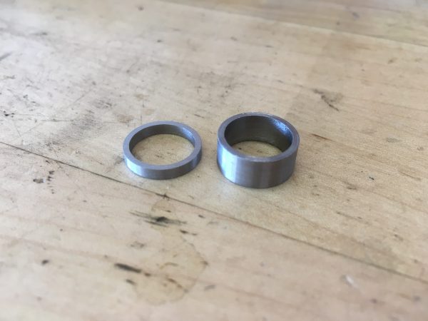
We’re going to make a simple piece of jewlery- a steel ring. It could be a ring for a finger, or you could hang it on a chain and wear it as a necklace. Perhaps your shopcat is very fancy and deserves a tail ring. There are a lot of options here.

Let’s get started! I’ll assume you have all the starter supplies I listed in the first post, and the usual stuff that comes with a lathe, but nothing else. Once again, a reminder that I’ll be working in Imperial units here. Everything will be in thousandths-of-an-inch (also called “thou” or “mils”). If that enrages my metric readers, I suggest meditation for 10 metric hectoseconds. That’s 16.67 minutes in the barbaric old-fashioned time system that we use here at Blondihacks Labs.
Before starting the work session, show your lathe a little love. Wipe some oil on the ways, hit any lubrication points that might need it, etc. After the work session, clean up all your chips and wipe up excess oil. A clean machine is a happy machine, and a happy machine is a precise machine. Don’t forget to show yourself a little love, too. Wear a face shield, keep your meat clear of that spinning chuck, and never touch the chips with your hands. Use a cheap paint brush to clear debris. One last safety thing that I should have said sooner: Never ever leave the chuck key in the chuck! It is a sizable missile and it will wreck your face with impressive efficiency. Some lathes (such as mine) have a spring-loaded chuck key that ejects itself when you let go. This is slightly less convenient to use, but a nice safety feature that I’m happy to have.
Okay, time to make some jewelry! Start by measuring the thing you want the ring to go around. For example, for a finger ring, measure the widest part of your second knuckle. Make sure you have a drill bit that size.
To start with, do some very basic lathe setup. Get your compound out of the way by setting it to about 30°. You won’t need it much when first learning. Next, put your turning/facing tool in the tool post, and swing it around to face the tailstock. Put the dead center that came with your lathe in the tailstock, and check the height of the tool bit.
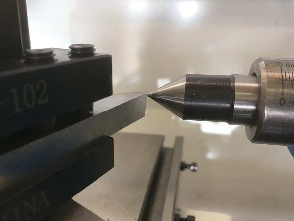
For basic turning operations, tool height is pretty forgiving. Facing and parting operations are very fussy about this, though, so take the time to set this up now.
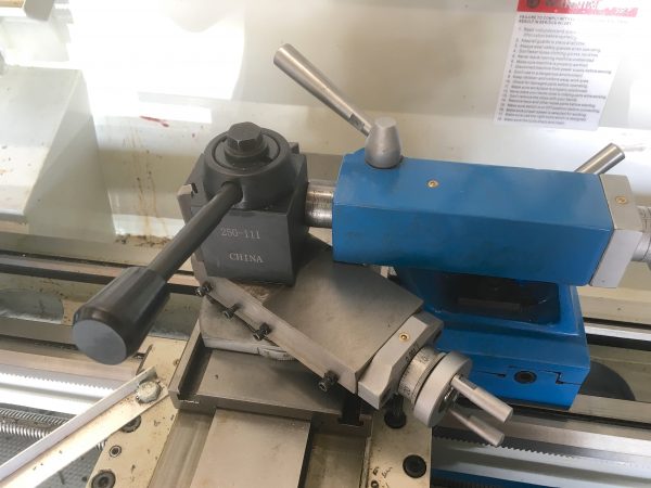
Next you want to get your tool post squared up again, since you swung it around to face the tailstock.
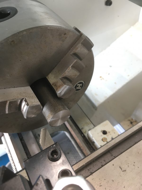
Now we’re ready to put our stock in the three-jaw chuck. The three-jaw chuck is slightly less precise and less versatile than a four-jaw chuck, but a whole lot easier to use. Choose stock that’s a few hundred thou larger than the hole in the ring will be. Mine is 500 thou, so I grabbed some 13/16″ stock (which is about 810 thou). I’m using 12L14 free-machining steel here, because it’s very pleasant to learn with. Always keep the area of the stock you are working on fairly close to the chuck. Precision is all about rigidity, and the further from the chuck you are working, the less rigid the setup is. It may not look like it, but even 1″ steel bar will bend ever-so-slightly when you start cutting on it a few inches away from the chuck. Remember the old fabricator’s adage: everything is a spring.
The first task in most lathe projects is facing your stock, and this ring is no different. The purpose of facing is to give us a reference surface on the piece. You can assume the lathe is all perfectly straight and square, but nothing on the stock is when we start. Facing makes one surface exactly perpendicular to the chuck. Every operation we perform relative to that faced one will thus also be precise and square. Even the most accurate saw doesn’t cut perfectly square, so always start by facing no matter how decent the end seems to be.
For facing, I like to put my turning tool in the back slot on the tool post. This spot is generally intended for boring bars and such, but it works fine for facing as well, and saves moving the tool post around all the time.
Time to make some chips! It’s also time to start getting a feel for feeds and speeds.
A good spindle speed to face stock this size is around 700rpm. Facing speed is always a compromise, because the closer you get to the center, the slower the surface of the material is turning. If you have a DC lathe, it’s easy to play around with the spindle speed a bit to get a feel for the effect of it. When in doubt, for stock this size, 700rpm is usually a good starting point.
What about feed? For facing on a small machine like this, I generally don’t go deeper than 10 thou in one pass. Maybe 20 thou if I have a lot to remove and I don’t want to be there all day. Experiment here and face as much as you want- length is not important at this point. Stick to manual feed for this first project. Power feeding is another skill set entirely that can wait for another day. Manual feeding is something you should acquire a feel for in any case.
Always lock the carriage before every pass when facing! Otherwise the force of the cutting will push the carriage outward, and your cut will not be square. This is a good time to look up how to lock your carriage in the manual for your machine.
What about feed direction when facing? Do you feed in or out? This seems to be a religious argument among machinists, and I’ve never heard a compelling argument either way (though people do love to argue about it). I personally face inward because that feels better to me. Maybe introverts face inward and extroverts face outward? Machining is a metaphor for life.
We can now set up for the second operation, which will be turning. Move your tool bit back to the normal position on the side of the tool post, and get it close to the side of the stock.
Here’s where we get our first try at being precise. Precision is a combination of skill, good work practices, and knowing your machine. Hold yourself to standards of precision, even when it doesn’t matter (such as a decorative piece like this). Hitting dimensions exactly takes practice, so take every chance you can get to try it.
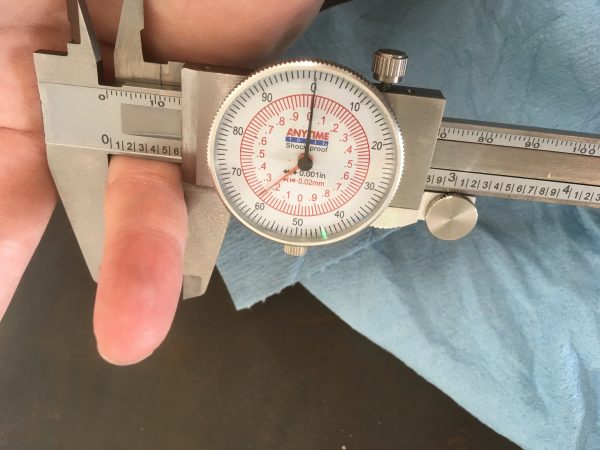
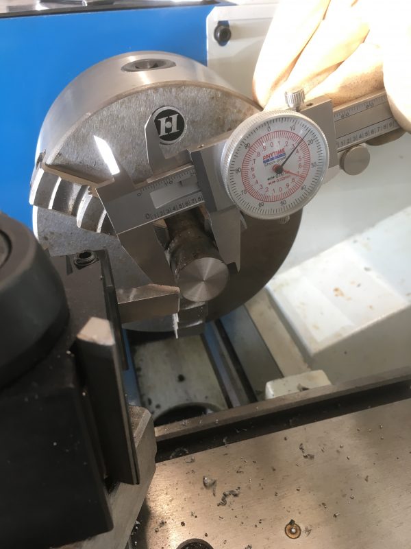
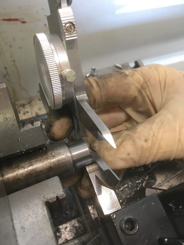
We want our ring to be 50 thou thick. Since the hole is 500 thou, we need an outer dimension of 600 thou (+50 thou x2 for each side of the ring). Start by measuring the stock so you know how much you need to remove. When measuring with a caliper, always wipe it clean before each measurement. Same for the stock. It’s easy to get debris in there that you don’t see, which will mess up the measurement. Squeeze the caliper gently but firmly against the piece, then tighten the slide lock thumbscrew. This keeps the jaws from moving while you remove the caliper, giving an accurate measurement.
My stock is 816 thou, so I want to remove 216 thou. It’s worth planning out your passes a little bit. When turning on my machine, I generally don’t go deeper than 60 thou in one pass. The machine will do 80 thou, but things sound pretty stressed at that point. Unless I have a long way to go, 40 thou passes are comfortable for roughing. So here, I might do five passes of 40 thou to remove 200, then do a 10 thou pass, theoretically leaving 6 thou. I try to undershoot by about 5 thou to account for any error. You don’t want to overshoot, because there’s no fixing that. You can always remove a little more. I try to leave a 2-3 thou finishing pass as my last one.
So how do you measure depth of cut? The dials on the feed wheels, that’s how. They have a ring that you can turn to set zero anywhere you like. From there, you can measure movement very precisely and repeatably.
There’s one gotcha in all this- you need to know how to read your cross-slide wheel. Some are “direct read” in that they tell you exactly how much is removed from the entire piece (the reduction in diameter). Some are indirect, which means they tell you how deep the actual cut is (reduction in radius). Since the piece is spinning, twice that much material is removed overall. Remember, you’re effectively cutting both sides at once. On indirect-read cross-slides, you need to mentally halve the cross-feed dial reading all the time. This is annoying.
The only way to be sure is to try it out. Feed in 40 thou from the surface of the part and do a pass. Then measure and see if 40 thou or 80 thou was removed. Now you know!
Okay, there’s a second gotcha- backlash. All geared mechanisms have lash (or slop) in them, and machine tools are no different. Backlash is not necessarily a sign of poor quality. Every machine has it, and you need to learn to work with it. Always approach the piece by cranking out a couple of turns, then back in. You want to have been cranking towards the cut for a couple of turns before the tool bit gets there so that the backlash has been absorbed. You can feel when you’re in “the lash zone” because the wheels get looser. Once you’re past the lash, know that reversing direction will cause your dial readings to be meaningless until you back out a couple of turns and come in again. This will make sense once you start doing it.
To get set up for turning, find the surface of the part by cranking the tool in until the bit just touches the stock. Remember to start from far enough out that you have cranked at least one full rotation before the part is touched (to take up the lash in the cross-slide). Once touching the part, hold the crank and turn the ring to read zero.
The dials on your machine will tell you the quantity represented by each tick. As you can see above, the cross feed on this machine reads in 2 thou increments. That still doesn’t tell you if it’s direct-read or indirect-read, so you still need to experiment to find out. The Precision Matthews (aka Weiss of China) machines are direct-read. This is very convenient.
Time to get turning! Always give the chuck a spin by hand before powering on, to make sure nothing will hit it. Move the bit past the end of the stock on the main axis, carefully feed it inwards 40 thou from your calibrated zero point on the cross-slide, then turn on the machine. Spread a little cutting oil on the spinning stock (with a brush only, never a rag or your fingers), since we’ll be making a fair amount of heat here.
Don’t forget to set your spindle speed. For turning a 1″ diameter piece, 700 rpm is a good starting point. Smaller diameters should be turned faster, and larger diameters slower. For cutting mild steel with HSS bits, a surface speed of 200 feet per minute is a good rule of thumb.
Feed across the piece at a gentle pace. Experiment a bit to get the feel for this. You’ll know when you’re going too fast. The slower you go, the nicer the surface finish will be, but that doesn’t matter until the final pass. You want to turn down an area about 400 thou wide, to give us plenty of room to work with for our ring. Be careful that you won’t hit the chuck at the end of your pass! Crashing the tool into the chuck is a very bad day, so always be mindful of it. If in doubt, do a dry-run of your operation with the machine powered off, and spin the chuck by hand to check for clearance at all points along the way.
At the end of your first pass, crank your way back to where you started on the main axis, but do not move the cross-slide! This is the key to maintaining precision. You’ve taken up the backlash and found the zero point on your cross-slide. If you touch that cross-feed after the pass, all that setup is ruined. Crank the main axis back so the tool is clear of the end of the stock, then ease your cross-feed inwards (never outwards) by the amount you want for the next pass.
When you get to your finishing pass, try to take off no more than 4 thou, and go as slowly as you can stand (patience is a virtue). Use both hands on the wheel, and practice being slow and smooth. When you get to the end, shut the machine off instead of cranking back to the start. That way you don’t risk scraping the tool on the way back and messing up your nice finish. Don’t touch the cross-feed though. Take your final measurement now in case you need to do one more light pass to hit your dimension. Only when you’re certain you’re done should you crank the crossfeed outwards and clear of the material.
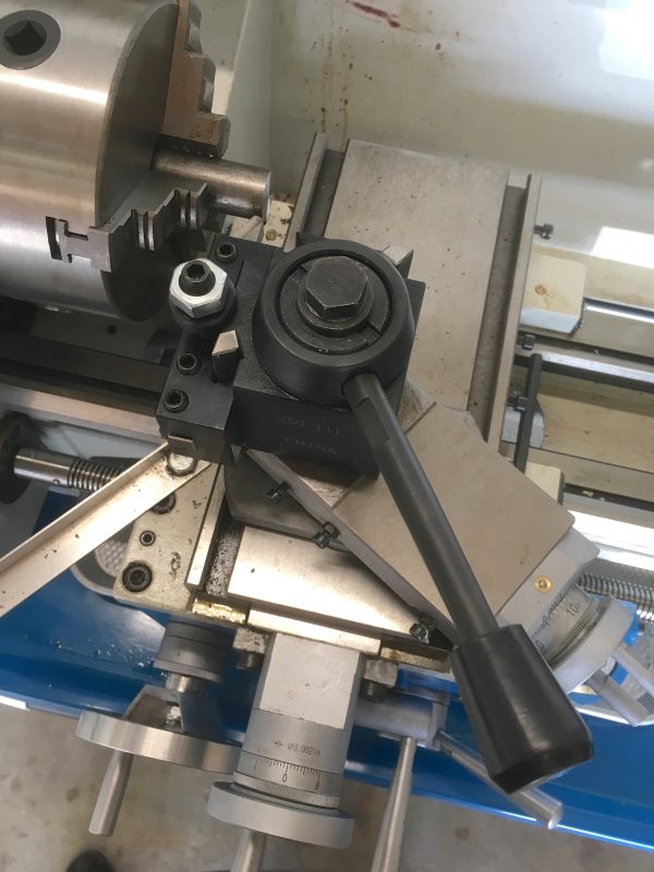
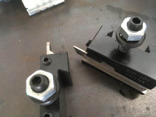
Now it’s time to switch to a parting tool. If you bought a pre-ground bit set, it likely came with one. Or you may have a cut-off blade. If you bought a quick-change tool post, it came with a cut-off blade holder. Any kind of parting or straight cutting tool will work here.
Parting on the lathe is a bit intimidating, and many people have trouble with it. We’re going to do a little trick here to ease you into parting without all the scariness. We’re going to make a parting cut, but only 60 thou deep (120 thou reduction in diameter). This is well before parting gets scary. Time to set up for that operation.
This parting cut will establish the length the piece (i.e. the width of the ring). 200 thou is a good number for a large ring, and 100 thou is good for a small one. This is a good chance to learn how to measure with the machine. No fancy DRO needed!
With the inside edge of the parting tool exactly on the faced end and the carriage zeroed, we just have to move the carriage in by 200 thou (or 100 thou for a small ring). The carriage hand wheel measures length for us once set up this way. Lock the carriage in place for the parting operation.
Find the surface of the part with the cross-feed, zero it, and apply liberal cutting fluid to the area. Parting off needs lots of cutting fluid, and it’s very important that the tool be centered. Double-check it now if you haven’t used that tool before. Use a speed a bit lower than you would for turning, and ease gently into the piece. Keep applying fluid. Yes, parting can be a bit scary, but remember we’re only removing 60 thou per side here. That’s cake compared to a full parting-off.
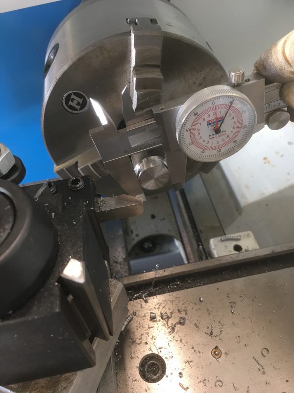
This step is important, so double-check with the caliper that your overall diameter is 120 thou less than the total ring diameter. In my case, my ring is 600 thou, so the parted area should be 480 thou.
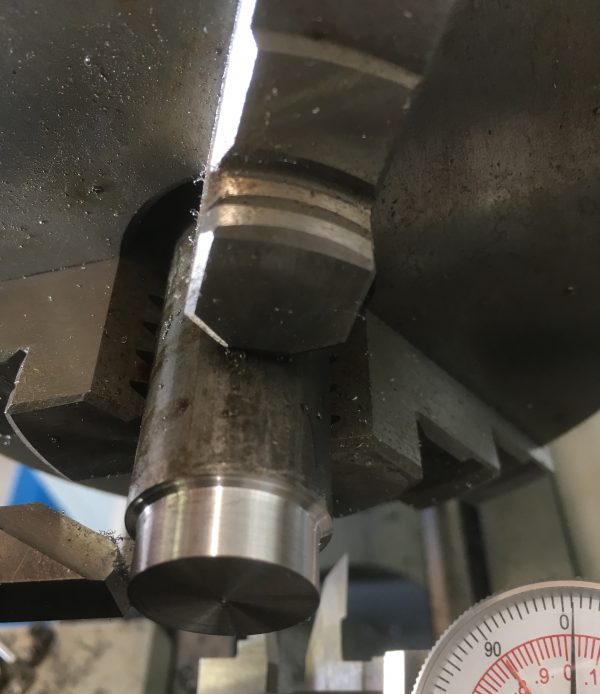
We’re almost done! The last operation is to drill out the center. Set up for drilling by putting your Jacob’s chuck in the tailstock. Center-drill with a #2 center-drill, as you did before, applying cutting fluid and sinking it in until you are 2/3rds of the way up the flared section. Center drilling serves a number of purposes. Center drills can’t “walk” on the surface of the material like regular drills do, so they ensure the hole is truly on the center axis. They also give a place for the normal drill to bite, since the point of a normal drill doesn’t really cut well. Speaking of normal drills, let’s get going with those now.
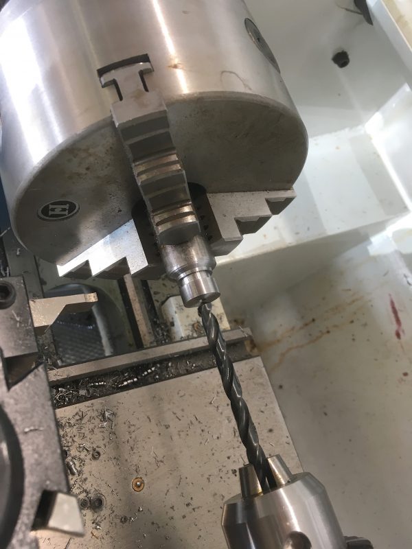
Use the markings on the tail-stock ram to judge how deep you are. We don’t have to be precise here, but we need to make sure we’re going about 400 thou deep to get thoroughly clear of the far edge of the part. Apply cutting fluid to the drill and occasionally pull the drill out to clear chips as you go. This hole isn’t very deep, so it’s very forgiving technique-wise. For a small drill like this, about 800 rpm is a good place to start.
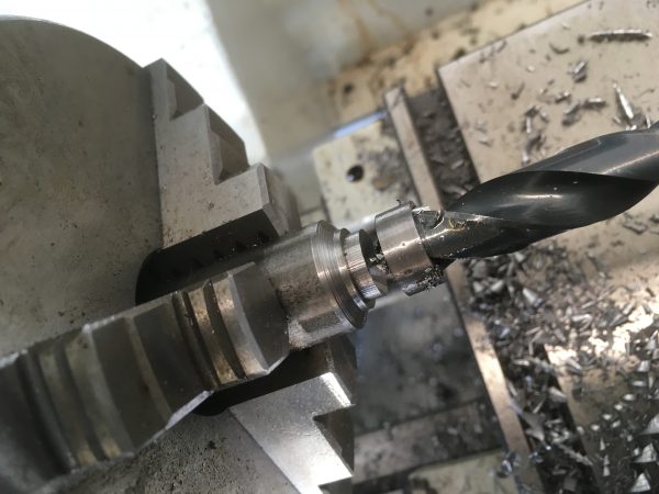
After that starter hole, come in with your final drill size (500 thou in my case). Slow the machine down for the big drill. Around 400 rpm is a good guideline.
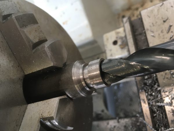
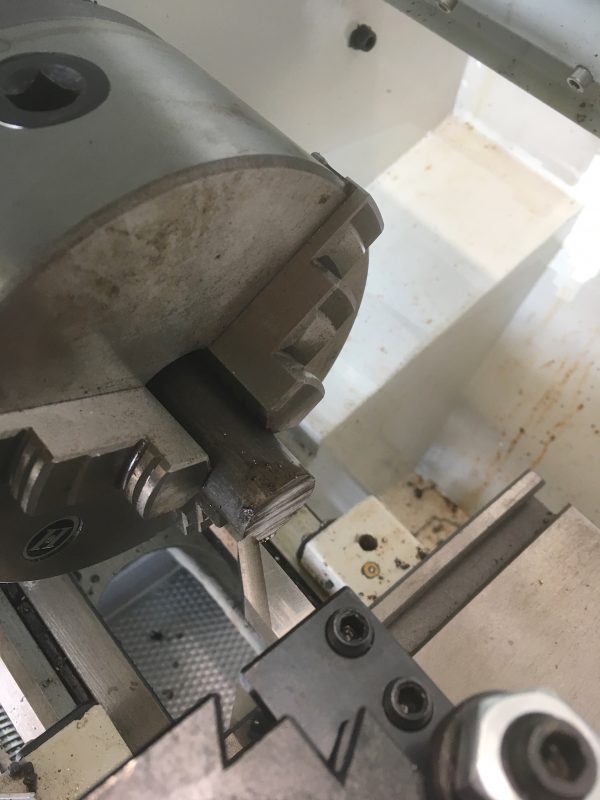
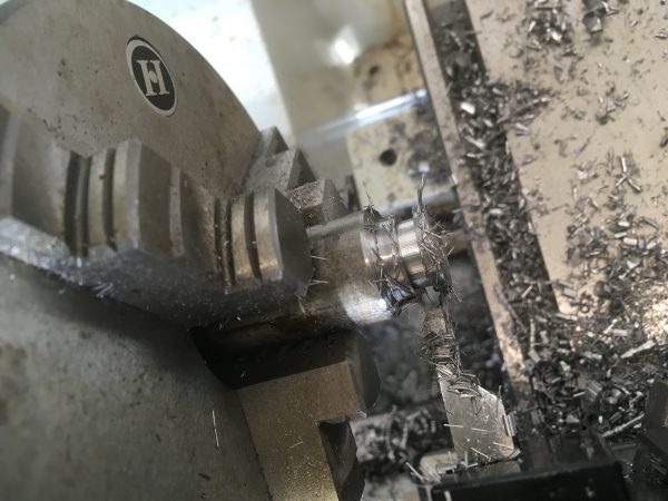
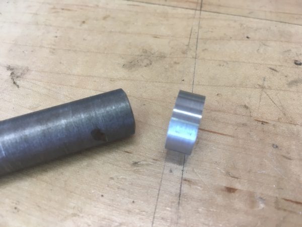
I tried to arrange the operations in this project to be as easy as possible for a first-timer. My favorite part is how the final drilling operation takes care of parting-off for us:
At this point, you can clean up any sharp edges with a bit of sandpaper if you like, but honestly I didn’t find it necessary. One word about materials- if you’re using 12L14 steel (as I suggested you should when learning), be aware it has about 0.3% lead in it. That’s not really the greatest choice for jewelry, especially for children. If you’re actually going to wear this a lot, consider sealing it with a clearcoat. You can’t get lead poisoning through the skin, but it can cause rashes in some people, and everything on your skin tends to end up in your food. The recommended maximum lead content in jewelry for children is 0.06%, and for adults it is 1.5%. You now have all the information, so make your own choice on this.
I’ll close with a discussion of surface finish. This is something machinists go on and on about, but what does it really mean? What do good and bad finishes look like? Let’s take a look.
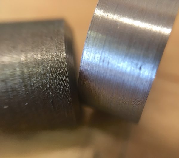
If your surface finishes are poor, here’s a list of things that might be wrong:
- Feeding too fast. The slower you feed, the better the finish.
- Cutting too deep. The shallower you cut, the better the finish.
- Chatter. If your tool bit is dull, or otherwise not cutting well, you’ll hear it.
- Carbide insert tooling. Put them down and walk away. They’re sexy, but small hobby machines don’t have the horsepower for them.
- Sharp-pointed tool. Tools like the Grizzly set benefit greatly from having the sharp point rounded over a bit. Rounded tools make better finishes than pointed ones.
- Lack of rigidity. Don’t work too far away from the chuck (without support), especially with thinner stock. Make sure everything on the machine is tight.
I hope that helps! Don’t give up- my surface finishes were awful for the first couple of months until I figured out all the many things I was doing wrong (and I still have much room for improvement). When you get it right, it’s really magical.

Okay, that wraps up the second in this introductory lathe series. I’ll have another project next time that builds on these skills to make another interesting widget (I promise- no bushings). Stay tuned, and keep on turning.
I was wondering why in the world you started into parting before boring drilling the center. Using the drill to bore the hole and part off in a single operation is a very elegant solution. I am a bit surprised that the edges did not want any easing, but that’s based on the shop videos I’ve seen, that have always given me the impression that a turning-meets-facing edge will be sharpish. Do you think you would have softened the edges a bit had you been sizing it for a finger?
“At which point they will uncomfortably shuffle off to get another drink and wonder what the hell just happened there.” – A possible sign that you’re attending the wrong parties.
Thanks! I was trying to come up with a way to make something with as few tools and operations as possible. Some parting turned out to be unavoidable.
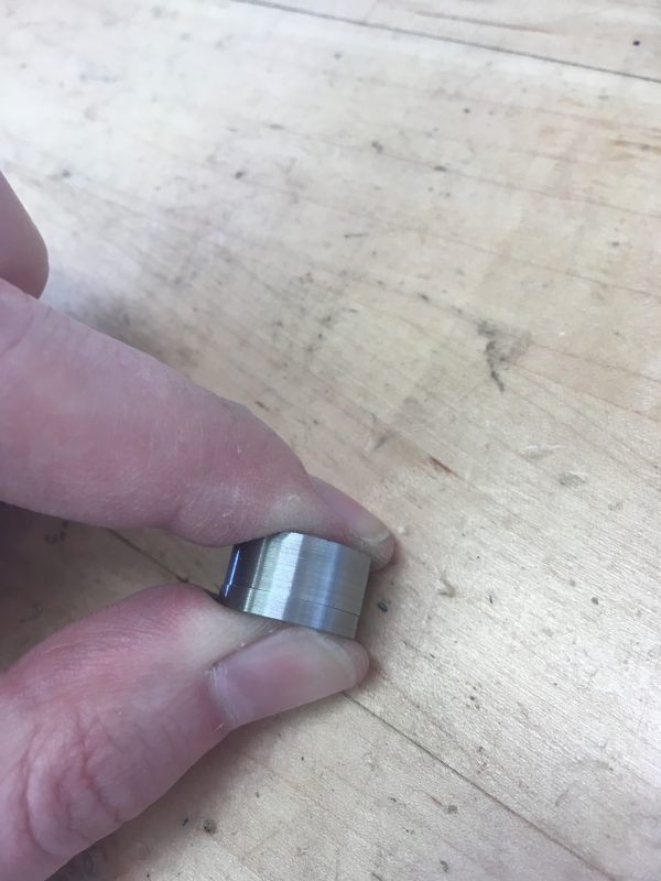
I actually can get part of my finger in this ring, and I tried it out. I found it to be comfortable. Under the high power lens, you can see a slight burr, and the finish on the edge created by the parting tool is not quite as good as the faced side, but it’s not uncomfortable to wear. If this were “real” jewelry, you’d want to sand and polish the heck out of everything anyway.
What a great article Quinn! Perfect for getting started using a lathe – I am saving for future reference 😀 Thanks!
Excellent stuff! How many revs does your lathe actually have? Your surface finishes would be much better if you up the revs to several thousand on the finishing passes. Carbide tips are ten thousand times better than gnarly old hss. We don’t even use hss in industry anymore.
You can always sand the dia with emery strip (we use reels of the stuff) and even go to scotch brite pads for smooooooth finishes.
With all the fun you’re having, you’ll be getting a mill, next!
It’s a horsepower problem. This machine will do up to 2000rpm, but at that gearing it loses most of its torque and can’t do a deep cut anymore. Carbide is great for big machines, but the minimum surface speeds and cut depths are just too high for a little 1hp machine like this. HSS is great because it performs nicely at low speeds. I wasted a lot of money on carbide inserts before I figured this out.
Great idea on the scotch brite- I’ll give that a go!
“We want our ring to be 100 thou thick. Since the hole is 500 thou, we need an outer dimension of 600 thou.”
wouldn’t that make it 50 thou, since the outer radius is 300 thou and the inner 250? or is this part of your imperial witch craft 😉
anyway, nice article. I love your tool setup posts!
Aha! Great catch, thanks for that. Ring shapes really mess with my brain. I had it right in my head when I made it, but then when recreating the steps while writing the blog post, there were too many 100s and 50s flying around. 🙂 I corrected the text. The ring is 50 thou thick.
Next project: inscribing some form of Elvish on the exterior. No matter how cliche that may be. 🙂
Although… how *would* one go about inscribing delicate strokes into steel. I imagine a diamond-bit Dremel could do it, but controlling it…?
Holding the ring in a small vise and using an electric engraver would work, although that takes a lot of skill to make it look good. The nuclear option would be a four-axis CNC milling machine, which could scribe perfect letters, rotating the ring as it went.
I wonder if some form of acid-etching could work, too. A modified PCB system or somesuch.
I think etching would work.
There’s a youtube channel called “Clickspring”, which has a series of videos on making a clock (with a lot of the work done on a lathe). For the face of the clock, he etches the design using ferric chloride, then fills it with shellac. The result is beautiful. https://www.youtube.com/watch?v=qpy5O0b7cL8
That’s brass, not steel, but no doubt the same process applies.
I’m a big fan of clickspring. His channel is one of the main things that got me into machining.
The etching process he uses is basically the same as many people use for circuit boards.