A 16-bit hexadecimal display module.
I’ve been wanting to take on more advanced digital design projects. I also like making multi-purpose tools and modules. It occurred to me that having something that can display a human-readable value from a digital bus could be pretty handy. I call it HexOut, and it’s a simple little module that can be plugged into an 8-bit or 16-bit bus, and display the current value. It’s a very rough prototype, and if it proves useful, I may rebuild it cleaner and smaller.
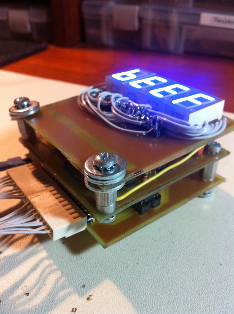
As you can see, the module is a three-layer design. The architecture is broken down into three parts- input, output, and display. This article will cover the top layer (display). Subsequent articles will cover the Output and Input layers. Let’s get into it!
The Display layer is the simplest. It has four seven-segment displays wired in a specific pattern to a 32-pin header which connects to the layer below. Here’s the schematic:
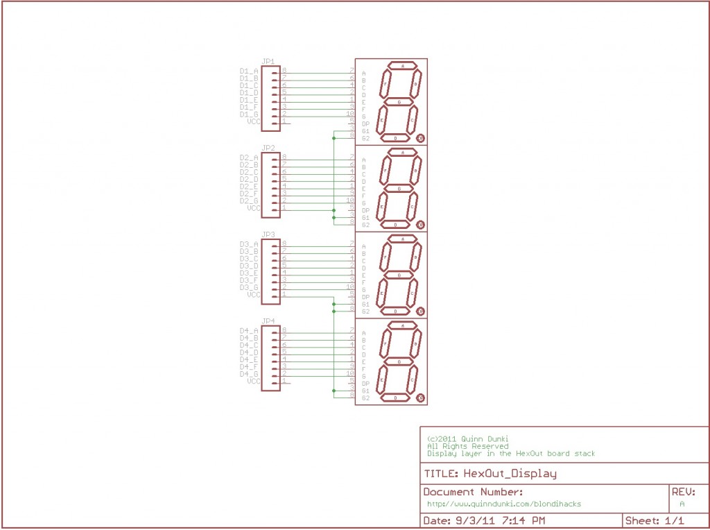
Here’s the Eagle file for the schematic, if you’re interested.The Display was developed simultaneously with the Output layer, which will be covered in the next article. As usual, I started by mocking it up on the breadboard, to make sure it works. If you look closely, you may notice my Bread Head and Juice Bridge projects are pitching in here.
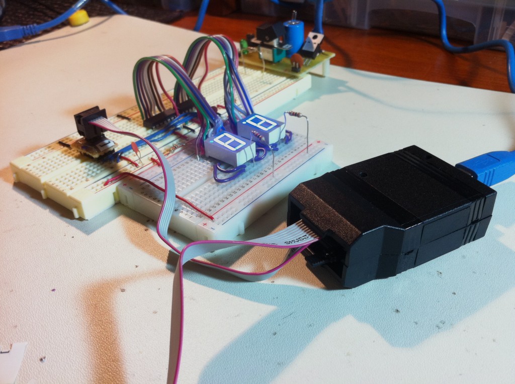
Once I knew this general approach to displaying my data was going to work, it was time for the PCB:
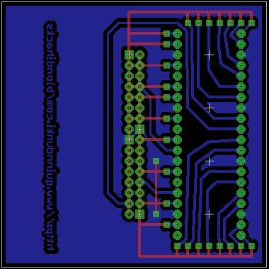
Here’s the Eagle file for the PCB. Like all my boards so far, it’s a simple one-layer design that relies on jumpers for the top layer. In this case, a lot of jumpers. It was a bit tedious to construct, but thanks to the jumper technique described above, everything was connected correctly on the first try. One interesting thing to note on this PCB is that the fill plane is actually Vcc. I’m using common-anode seven-segment displays, because it’s what I had on hand. It was much easier to lay out the PCB for these displays using a Vcc fill plane instead of the usual ground plane. The displays are ultimately driven by 74HC595 shift registers, which are better at sinking current than sourcing it, but they can still drive these displays just fine. However, it does mean the LEDs are effectively active-low, which means we need a low voltage to turn them on, and a high voltage to turn them off. That oddity is easy to correct for, as we’ll see later.
Something else to note on this PCB- there are no drill holes for standoffs in the corners, even though it’s part of a PCB stack. This was a mistake on my part, which I had to rectify with some creative rejiggering later. More on that after we go through all the boards.
Once I had the PCBs, it was off to etch. A little spoiler here- I actually designed and laid out all three PCBs at the same time, since that was much easier. For the purposes of these articles, however, we’ll just focus on one at a time. I etched the board using my usual process. The acetate for this layer is available here, and all the acetates together look like this:
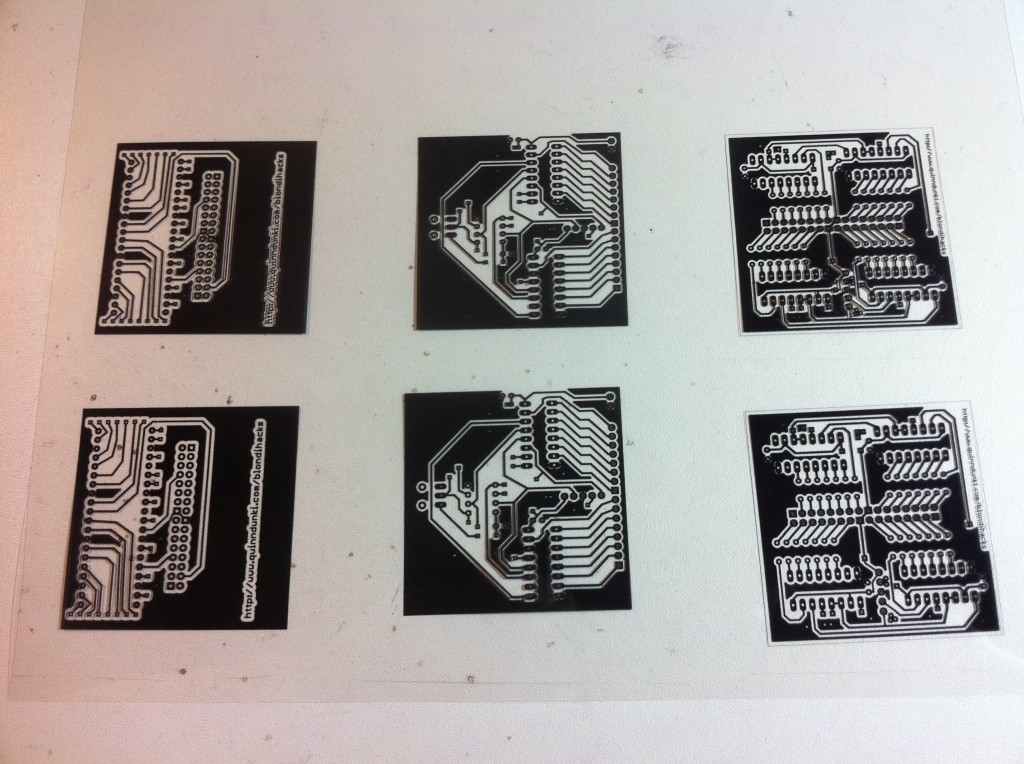
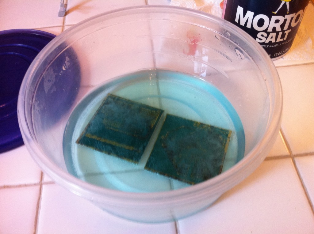
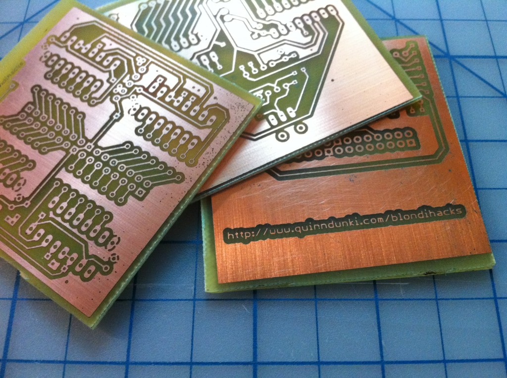
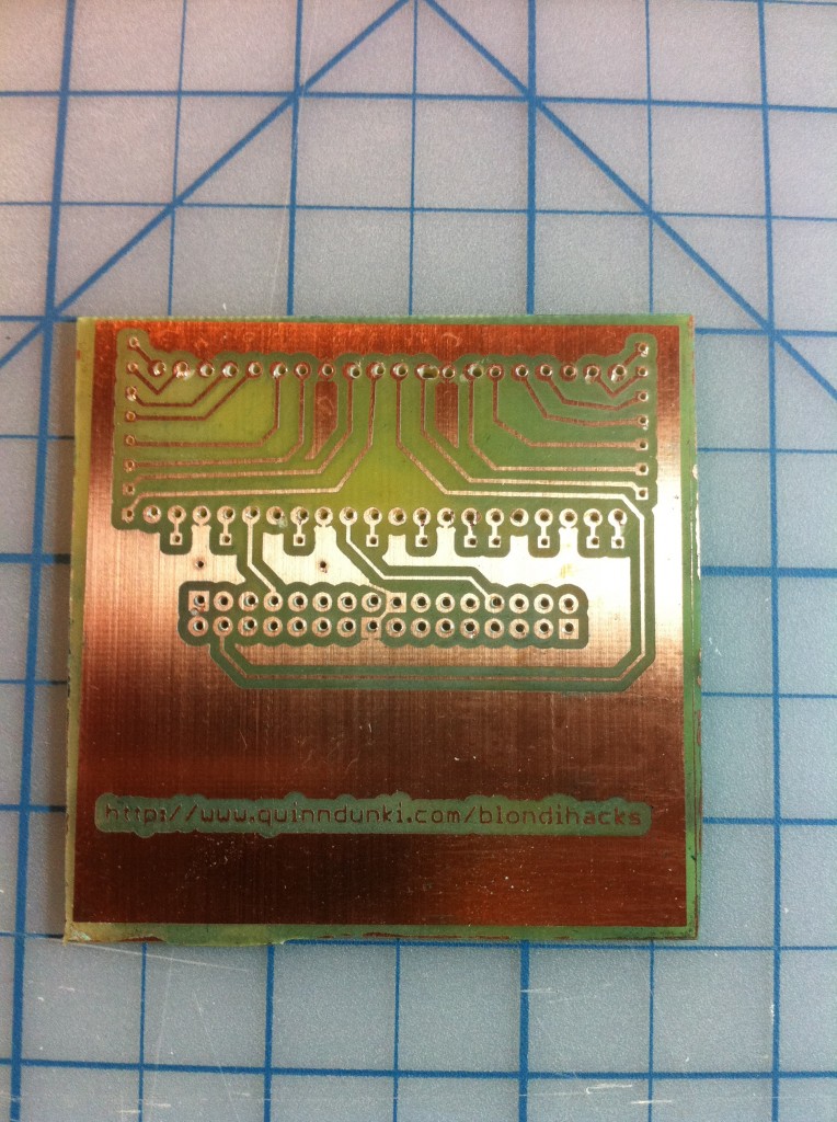
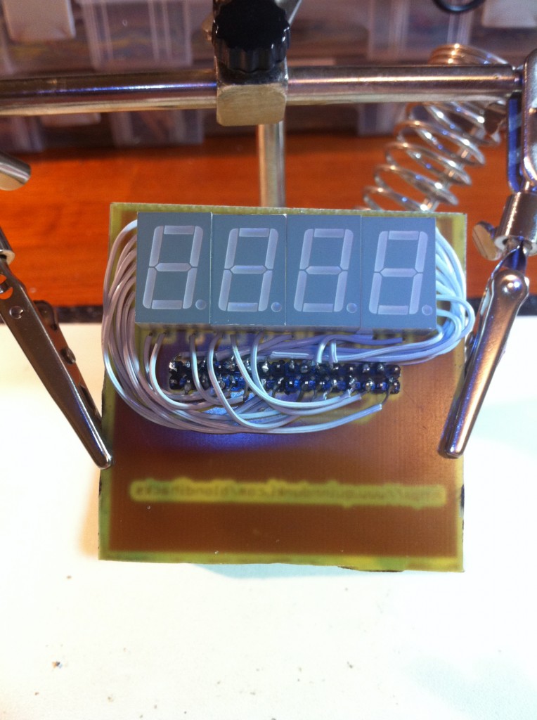
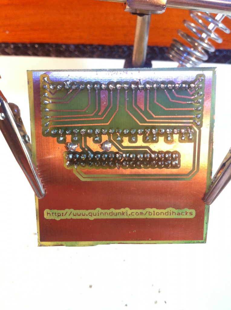
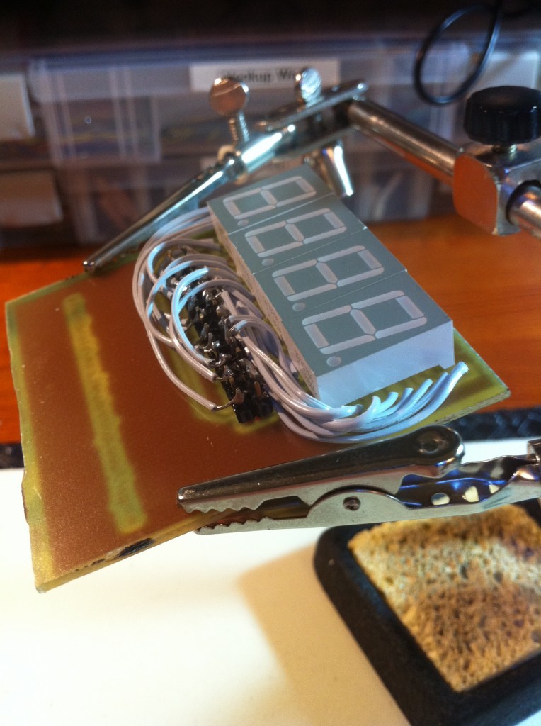
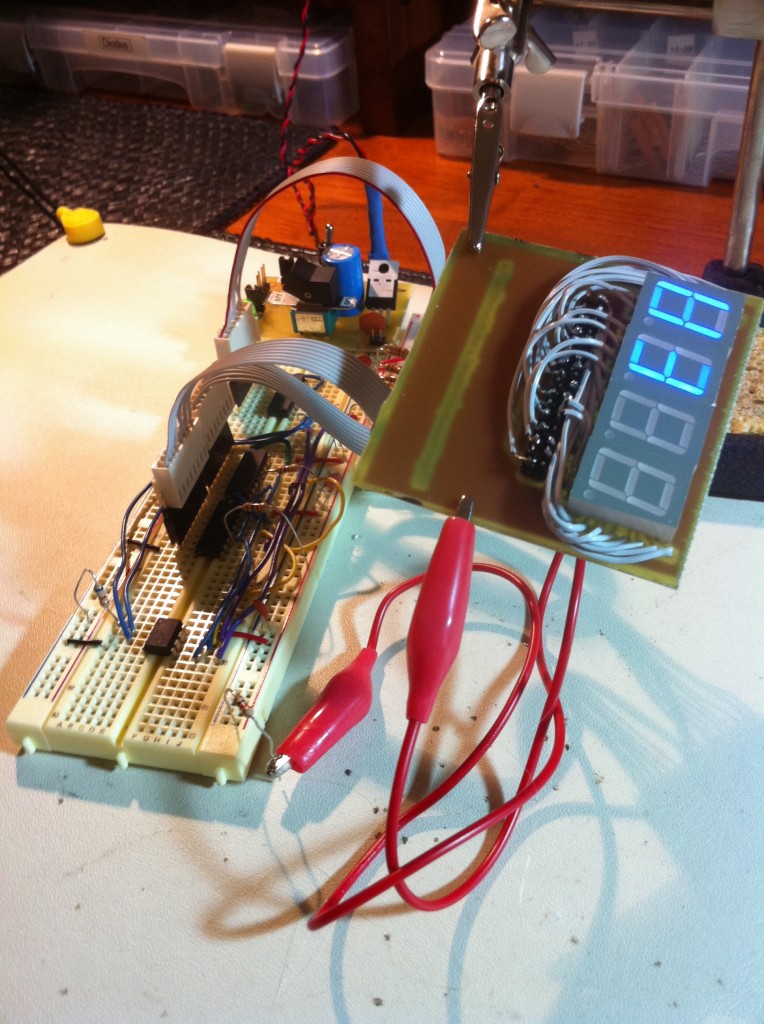
That wraps up part 1 of HexOut. In part 2, we’ll dig into the next layer down, which is where some real digital design starts to happen.
Very retro 😉
You might want to consider adding a buffer board w/ 2-4k of 16 bit wide SRAM, a counter and trigger logic to start and stop the counter. You could make that modular also by allowing for different trigger modules, e.g. single pin or start/stop when a particular word appears on the bus.
Nice job.
Cool ideas Reg, thanks! I’m sure there will be another version of it soon enough, once I’ve used it in the real world for a while. Stay tuned for the next two parts of this article!
very cool project again! best part, no adrunios! i have needed to do a very similar thing once because they are nice and handy, also did one for input (keypad).
nice work “ma’am”…or would you prefer “dudette”?
Blondihack,
Just wanted to say that I have enjoyed reading about your experience interfacing the 6502. As a matter of fact, I have enjoyed it so much that I this I want to follow along with you so to speak. I have bought a processor, sram, eeprom, crystal osc and stuff to get started.
Anyway, I posted here because I have a circuit I want to share with you. I would like to make a hex display like you done, but I don’t have a ATmini. So I thought I would do it a little more old school. I am using a 4 to 16 line decoder with a diode matrix ROM to drive the display. I have bread boarded it with a two to four line decoder to prove the concept. If you email me, I will share the circuit with you and you can give me some input. I have not done any electronics in quite a few years, so a second pair of eyes would be good.
Thanks for the inspiration.
Joe