Bit-banging a VGA signal generator.
Computers aren’t very exciting until they have a display of some sort. Well, I suppose if you’re at Bletchley Park trying to crack Enigma codes, computers are pretty exciting without a display. World-saving cryptography aside, I want Veronica to show pretty pictures. The usual route for a display on home-brew computers is composite video, because that’s fairly simple to generate. However, I haven’t had a device in my house that can display a composite signal since the 1990s. Herein lies the rub with old computer hardware- it’s not really the machines themselves that stop being usable. It’s the peripherals. Mechanical disk drives wear out, magnetic media goes bad, and video standards fade into history (so to speak).
For Veronica, I’d like to have video output that is relatively modern, so that I have some hope of connecting it to things. VGA seems like a good choice, because it’s now sorta retro, but still widely supported. I didn’t know a damn thing about VGA when I started this, so it has been pretty educational. It turns out that it’s a really simple standard. You just need a horizontal sync pulse, and a vertical sync pulse. Everything in between is pixels (more or less), based on an analog voltage on the red, green, and blue signal lines. One catch is the data bandwidth. To get any sort of decent resolution, you need to be able to push pixels at a good rate. The standard 640×480 pixel clock is 25.175Mhz. That’s much too fast for Veronica’s 6502 to crank out, so we need another solution. A number of old computers and game consoles used a separate custom chip to generate video, and I can see why. Nowadays, we’d call this a GPU, and much like modern-day, Veronica’s GPU will be considerably more powerful than her CPU. No shame in that, right? Also, 15″ VGA LCD monitors can be had for less than the cost of a nice lunch over on eBay.
While generating a VGA signal is fairly straightforward, it still takes quite a bit of hardware to do it. Instead, I can “cheat” and generate the requisite signals in software on a microcontroller. Sneaky options like this are available to us these days. It will be a quick way to get up and running, and allow me to focus on other problems that I’m more interested in. Before I proceed, I’d like to give a shout-out to a few folks. Like all my hacking, this project didn’t spring forth from a vacuum. I’m standing on the shoulders of giants here. A lot of research has gone into this project, and the following resources have been really valuable:
- Wikipedia’s VGA standards page
- LucidScience’s ATmega VGA generator
- Alfersoft’s ATtiny VGA generator (this link may be broken, sadly)
- The TinyVGA project
The VGA signal is pretty simple. Each horizontal line consists of a “front porch” (high signal), a sync pulse (low signal), a “back porch” (high signal), and a section of active video (analog). Each of these sections needs to be a specific length for the monitor to lock to the image. The horizontal line is analog, and the resolution basically depends on how fast you can push pixels out during this period. The vertical scanning has the same front-porch-sync-pulse-back-porch structure, but is measured in lines instead of time. There are 480 vertical lines. The sync pulses and “porches” make up the “blanking periods” on both the horizontal and vertical portions of the signal, which is when the electron beam on an old CRT would reset back to the start of the line or screen. I won’t go into gory detail on this here, as others have done a good job of explaining it (see the resources above, for example).
Veronica’s VGA signal generator is based on an ATmega 324PA. I chose this chip because it can run fast (20MHz), and has wide I/O. At some point, I’ll need video memory, which will need a lot of pins. For now though, I’m just spitting out the VGA sync pulses and generating some test pixels procedurally. This method of generating pixel values on the fly rather than pulling them from video RAM is sometimes called “racing the beam”. This is how the Atari 2600 generated video, and is the reason those games had that distinctive look that we all remember fondly.
In summary, I like to use the smallest thing I can that will do the job adequately, and the ATmega 324PA seems to be it. It’s not all puppies and unicorns, though. While the chip can run at 20Mhz, the I/O bandwidth is only 10Mhz. This is far short of the 25.175Mhz required to generate the standard VGA horizontal resolution of 640. However, we can cheat here once again. If we push pixels at the ATmega’s maximum rate of 10Mhz, the monitor will average things out and we wind up with a horizontal resolution of 256. Furthermore, if we double up the vertical lines, we get a manageable vertical resolution of 240. This also means all screen coordinates will fit into a byte, which will be a huge advantage for the 6502 when it needs to talk to my new GPU. A resolution of 256×240 gives a slightly weird aspect ratio of 1.06, which means the pixels won’t be square on a standard VGA monitor (which has an aspect ratio of 1.333). That’s livable, and was actually pretty common on 1980s computers. Many of them had weirdly-shaped pixels, due to similar technical compromises to the ones I’m making here. Special thanks to LucidScience for working out this resolution. It’s a great approach for VGA on an ATmega.
First things first- before I can write any code, I need a programming header. I haven’t used one of the big 40-pin AVRs before, so a new Bread Head was in order.
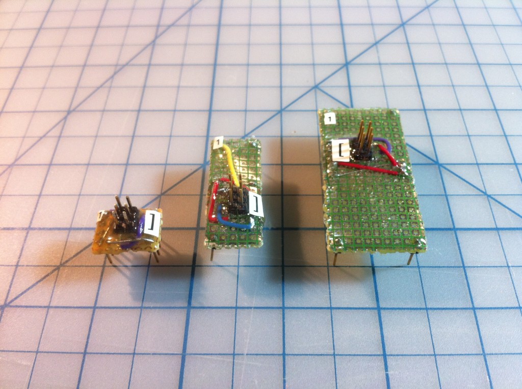
Okay, on to the code! The primary technique here is to calculate how many clock cycles will make up the required length of each phase of the VGA signal at the clock speed of the micro controller. You find these by cross-multiplying the clock speed you’re running at with the standard VGA rate of 25.175Mhz, and the phase lengths specified in the standard. Here are the clock cycle counts that I’m using. This is partly based on the work of others (LucidScience in particular), and also on my own experiments with what worked well:
- Horizontal front porch: 12 cycles
- Horizontal sync pulse: 76 cycles
- Horizontal back porch: 33 cycles
- Horizontal pixel clocks: 512
- Vertical front porch: 11 lines
- Vertical sync pulse: 2 lines
- Vertical back porch: 32 lines
- Vertical pixel lines: 480
These values work for me to get a monitor to lock to the signal at 640×480 with a refresh of 60Hz. There is some wiggle room. If you’re a couple of cycles off one way or another, I found that it still works. If you get too far out, you’ll start to get artifacts or (more often) the monitor will refuse to lock to the image. So, we need to write code that generates the sync pulses with those exact timings, and generates some analog pixel values during the visible part of the scan. This has to be done in assembly language, because you have to know exactly how long every instruction will take, so that you can guarantee the timing. It also means using interrupts, as they are the only reliable way to get this kind of realtime precision. While I have experience with assembly and interrupts on other chips, I’d never used either on an AVR. Fortunately, assembly languages are all basically the same. The AVR has some pretty fancy interrupt techniques that required some quality time with the documentation, but it’s not too difficult to grok.
Developing this code is a bit tricky, because until it’s nearly perfect, the monitor won’t lock to the signal, and you’ll just see The Blackness Of Failure. It’s not like an old television which would display anything that was sort of close, even if it resulted in a lot of static, rolling, Bob Saget, or other unpleasant artifacts on the screen. To get the basics right, I started with the oscilloscope. Until I figure out the image-export feature on my scope, you get to suffer through photos taken of the screen.
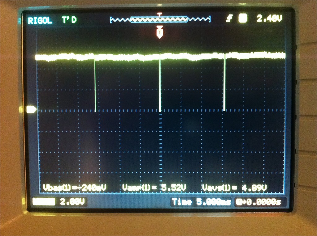
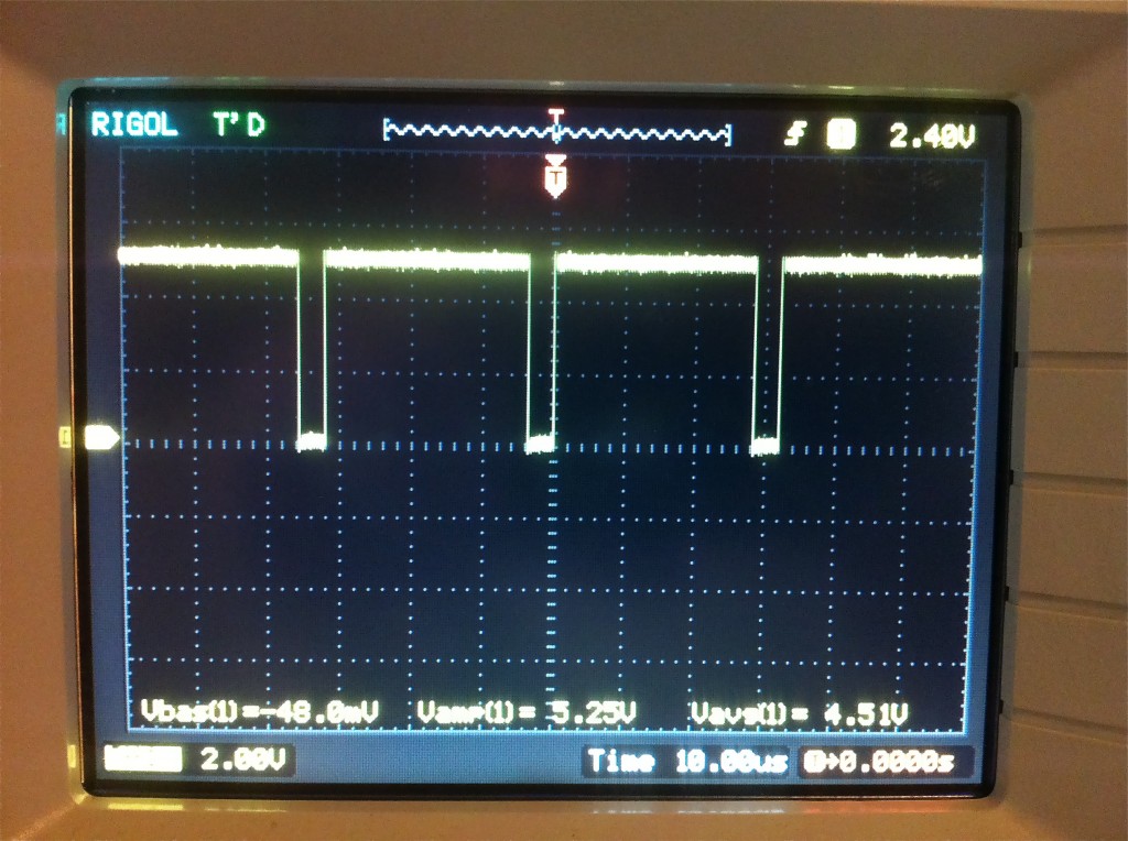
The sync pulses are generated from an interrupt service routine that fires based on one of the ATmega’s built in timers, every 636 clock cycles (the length of a horizontal line at 20Mhz). After getting the timer and interrupt code set up, I wrote the code to generate the pulses, counting cycles to make sure everything lines up. The ATmega data sheet lists the cycle counts for every instruction, so it’s just a matter of doing a lot of arithmetic. It’s quite a fun challenge to write assembly code to hit a very specific cycle count. Especially when you get into branching and loops, in which case you have to make sure every possible code path uses the same number of cycles. I had a couple of bugs in my code where one branch would take more or less cycles than another branch, which would cause slight timing differences. The symptom was the pulses on the oscilloscope would jitter slightly as the timing variations were averaged out. This is enough to make the monitor refuse to lock to the signal. This is an example of where getting things right on the scope first was crucial to success. Plugging in a monitor will tell you very little about what is wrong.
Okay, now that the sync pulses are ready, let’s generate some pixel data! For that, we need more hardware than just a naked ATmega. The red, green, and blue signals are analog, and I have a 8-bits available for the colors. For now, I’m going to give two bits to each color component, and ignore the extra two bits. That gives me 64 colors, which is plenty, honestly. It’s certainly far far more than most 6502-era computers had. To convert the two-bits-per-component into three analog signals, I’m using three small resistor ladders.
Here’s the schematic (and Eagle file) that I ended up with:
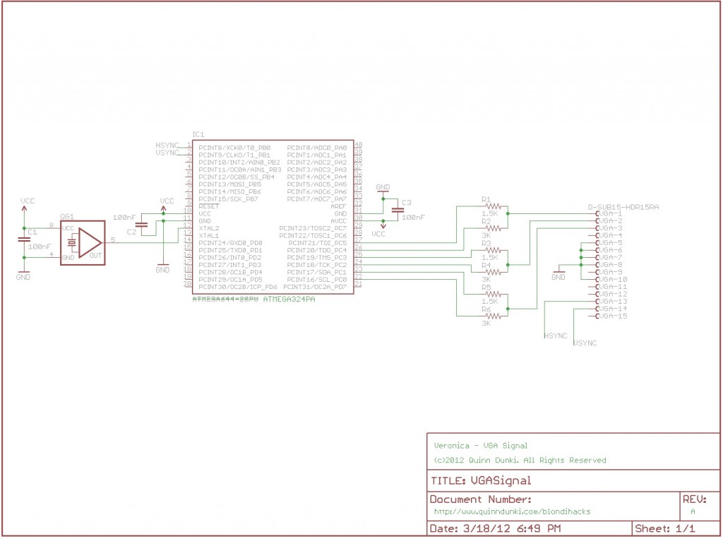
When using a resistor ladder used for digital to analog conversion, the need for resistor precision increases exponentially with the number of bits. With only two bits in each ladder, it normally wouldn’t be too critical. However, because we’re generating three color components that will be mixed by the monitor, the relationship of the ladders to each other is important. If they don’t match well, the resulting image will have a slight red, green, or blue tint. I opted to use 3k and 1.5k resistors to make each 2-bit DAC, because I happen to have those values in my box. Almost any 2:1 ratio should work. Next, I measured all the resistors I had in those sizes with an ohmmeter, and tried to find three of each that were exactly the same size (within the limits of my ohmmeter). I managed to find three that were exactly 1.476k, and three that were exactly 2.951k. The ratio of the resistors to each other will affect overall vividness of the colours, but the relationship of each pair to each other pair will affect overall tint. I felt it was more important to get the tint right.
So, with that all wired up, I added a loop to my interrupt routine to spit out some RGB values during the portions of the frame that are active pixels. I verified this on the scope:
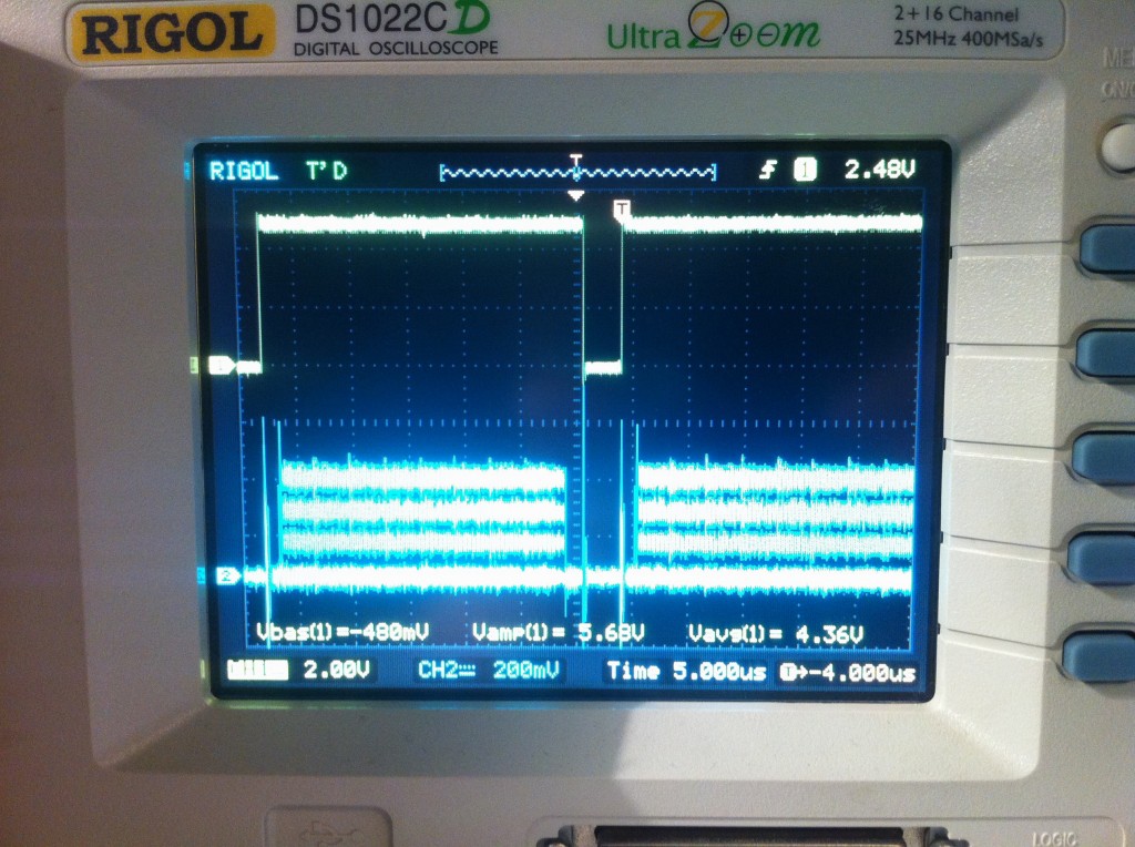
Looking good! The code in question should be rendering all my 64 colours, in an 8×8 grid of blocks. Let’s plug in a monitor and see what happens!
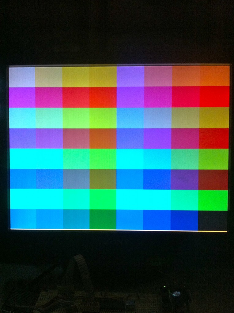
Okay, okay, it wasn’t that easy. It took a fair amount of debugging the code to get to this point. Once the sync pulses were working, I started by showing a solid color, then vertical stripes (by getting the code for one scan line to work), then the blocks you see above.
Interesting sidebar, I spent a long time debugging what seemed to be muddy-looking colours. My “white” in the upper left seemed kinda gray. I learned two things while debugging this:
- Our perception of a color is greatly influenced by what colors are around it. To really test changes to a color, you need to see it in isolation.
- The backlight on my cheapo eBay screen is shit. The colors vary quite a bit depending on where on the screen they are. The eBay seller was less than honest about the condition of this display, I’m afraid.
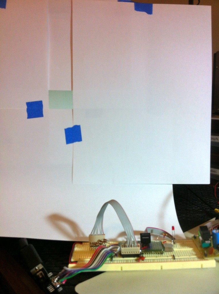
I determined all this by setting up a mask for a single color block in my test pattern. I could then move this mask around while changing the code to verify that colors in different locations look right.
Here’s the final version of the signal generator code. I’ve indicated the clock cycle counts of each line and section in parentheses. This is avr-as assembly, so you can build it with avr-gcc, or (I suppose) the Arduino environment. The only really tricky stuff is that branches take a different number of cycles depending on whether the branch is taken (2 cycles), or falls through (1 cycle). To compensate for this, you’ll often see a ‘nop’ following a branch, so that both code paths are the same length. You’ll also see stretches of ‘nops’ anywhere that I had extra time to fill. The “porch” areas are used to set up loop counters and such for rendering the test pattern. During the active pixels portion, there’s no time to spare. In order to get pixels pushed out at the ATmega’s maximum I/O rate of 10Mhz, we need to be updating the output pins every two clock cycles (since we’re running at 20Mhz).
[iframe_loader src=”http://pastebin.com/embed_iframe.php?i=HpnSy7Yv” height=”600″ scrolling=”yes” marginheight=”50″]
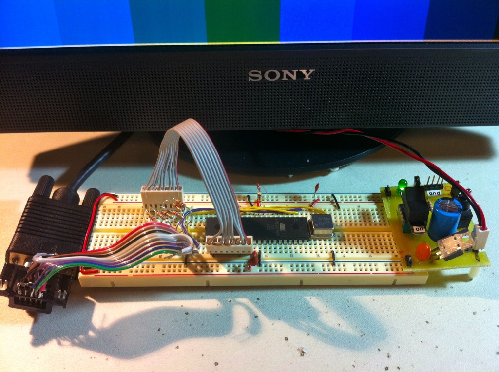
So far so good! I guess the next thing will need to be video memory, because there isn’t enough time left to do much more with this old school “racing the beam” technique. Stay tuned!
I can’t wait to see how you handle the memory mapping between the two devices, especially ensuring they don’t both try to use at the same time
I’m not quite sure how you will be interfacing the 6502 to the video generator, but I think you want to use the 6502 to generate the graphics by writing to video memory and have the atmega handle the display timing. Years ago I bought some special drams from TI that were dual port video memory. The processor wrote into the parallel bus of the drams just like regular dynamic memory ras, cas, and all. But these chips also had an on board shift register that could be loaded using a special read mode and then shifted out to be displayed. The shift register side could run at high speed (50mhz?) while the processor side ran slower. Even neater these drams were self refreshed from the video load timing. (I don’t know if video drams are still being made though).
Actually you have a point. The pixel-dumping part, at least, of a video generator, just needs to increment an address constantly, then feed that address to the video RAM. Take the data byte the RAM returns, output the correct amount of pixels (ie 4 bits / pixel = 2 pixels / byte), then increment the RAM address for the next couple of pixels.
This could all be done in hardware. The porch stuff too. Tho a compromise might be best, a microcontroller does the porching / other timing, then sets a counter going for the pixels of that line. Say the counter counts to 256, that’s 512 4-bit pixels. Then when the counter overflows, signal the controller it’s time for another timing signal.
Basically use discretes and software together, each at what they’re good at! You might even be able to add a hardware sprite or two, if you were lucky. Or maybe a display list, like the Atari 400 / 800, where the start address of each line of pixels is programmable, by giving the Atmega a list of addresses. The advantage of that, is that it allows full or part-screen scrolling with NO cpu usage!
For sprites, perhaps store their attributes / bitmaps in the Atmega’s own RAM , over-riding the picture in the system’s screen RAM in some clever way!
The Atari 8-bits in particular had beautiful, powerful graphics hardware. Very similar to the Amiga’s. Colour-bars with no CPU load! Would be nice to see a tribute to that, and it would make impressive games on your computer much easier. Fast, colourful graphics! And of course the Ataris ran 6502s.
I agree with Jacob — dealing with the 6502 and AVR contending for the memory at the same time will be interesting. You could go the Apple ][ route and flip access back and forth between the two, given each one access for half of a clock cycle.
Plus… I was working on this sort of project a while myself, and I couldn’t figure out how to read video memory fast enough to display it. You can’t do it pixel-by-pixel, because reading external memory is going to take longer than the two cycles per pixel you have available. (Even with composite TV timings, which I was using, I could just barely write memory contents to the screen using four cycles per pixel.)
I wish you the best of luck — Veronica is a fascinating project! I was also wondering what license you’ve released the code up there on — I’m trying to do video generation with an XMEGA running at a higher speed, and while I could go ahead and use my old code, yours is frankly nicer looking and better documented!
Reminds me of this demo, which does an impressive amount of vga graphics (and sound) on a ATMEGA88: http://www.linusakesson.net/scene/craft/
I[m Looking forwards to seeing how you manage to interface this to the rest of the computer.
One more thing I just noticed: in line 79 of the above code, don’t you want to be storing into OCR1AL instead of OCR1AH?
Hey, you’re right- that is a bug!! Thanks for catching it! I’m pretty surprised it’s working like that, actually. 😀
I’ve fixed it now.
Good to see some AVR assembler code in here! I wonder if you’ve seen the Lucid Science AVR-based video generator:
http://www.lucidscience.com/pro-lazarus-64%20prototype-1.aspx
And their VGA generator:
http://www.lucidscience.com/pro-vga%20video%20generator-1.aspx
They seem to use a similar technique, but with double-buffering in the case of the Lazarus-64.
Indeed, I definitely got some ideas from LucidScience, and make reference to them a couple of times in the article. Their site is great (except for paginated articles 🙂 )!
Yes, and of course, as soon as I posted that, I spotted your link in the article to Lucid Science! What was I thinking? I must’ve been in need of some strong coffee or something. Anyway, here’s my ATmega324 generating monochrome video on a tiny TV:
http://www.flickr.com/photos/anachrocomputer/5070700349/
And here’s my colour video test pattern, on the big plasma-screen TV at Dorkbot Bristol:
http://www.flickr.com/photos/anachrocomputer/5098639443/
I’m generating RGB video, as you are, not PAL or NTSC as Lucid Science does. But I’m generating it at UK broadcast TV rates (50Hz/625 line), not VGA rates.
It’s okay, I’m only dimly aware of where I am and how I got here most of the time. Thanks for sharing the links- nifty stuff!
Great to see some progress on the project again!
For those who are wondering how this will be connected this to Veronica:
I think I mentioned this before: in most early 6502 systems, the system clock was based on the pixel clock so the 6502, and the video controller would simply use the first half of each clock pulse to do its work while the 6502 uses the second half. As it happens, a 40×25 character text screen like the one on the early Commodores and other machines would result in a character reading speed that was very close to 1MHz if the video was refreshed at 60Hz. They simply used a couple of 74xx257 chips (quad 2-to-1 multiplexers) to switch the address bus inputs on the video memory between the 6502 address bus and the video controller address bus, and controlled the multiplexers from the CLK2 output of the 6502. The data bus was simply shared between the video controller and the 6502.
The problem with this approach was that (1) the video was pretty much locked to one possible resolution based on the system clock, and (2) On color machines, PAL versions would run at slightly different clock rates from NTSC machines; PAL was slightly faster because 720x576x25 (PAL pixels/second) is more than 640x480x30 (NTSC pixels/second).
In other systems such as the CGA adapter on the IBM-PC, the clock frequency for the video is independent from the system clock and the data bus of the video controller was separated from the system data bus: The video controller would continuously read data from the memory but whenever the processor would access the video memory, both the data bus and the address bus of the video controller would be disconnected from the memory for a short time causing flicker on the screen. Well-behaved programs could use the vertical blanking time to update the entire video buffer, and/or update one or a few characters during the horizontal blanking interval.
So really, all you need to connect this to Veronica is an address bus decoder that maps the video memory into the 6502 address space, some logic that disconnects the video memory from the video controller temporarily and connects it to the 6502 whenever a read/write to/from the 6502 is detected, and the ability for the 6502 to check the horizontal and vertical blank pulses on a different address.
In my own project, I just avoid the issue by letting a Propeller generate the video and mapping the Propeller memory into 6502 address space but once again I’m amazed to see you found new(?) ways to do it in a totally different way. Cool! 🙂
===Jac
Hey guys, Marcelo from GarageLab community is also trying to generate VGA signals with ATMEGA, but he is trying with ATMEGA328 on an Arduino board. Check out some cool results: http://garagelab.com/forum/topics/vga-signals
I was just curious why you didn’t use a small FPGA or CPLD to generate the VGA signals? wouldn’t it have been easier to time the system and add in (later on) vram?
though I suppose getting it to talk to the slow 6502 would be a pain in the rear. . .
That’s easy- because I don’t have the tools to make FPGAs or CPLDs. 🙂 In any case, I have other plans for this as well. It may only be generating sync pulses now, but it will be doing a lot more soon enough.
Really great job!
I have a AT90S8535 with 8K bytes in-system programmable 8MHz can be enough to do the same work your ATMEGA324PA?
Dear Quinn,
I’m amazed at your attempt of making the VGA signal generator in an 8-bit microcontroller and the results are pretty cool.
Recently, I’m developing a program which generates TV (NTSC) signal from the PIC32 microcontroller, with no luck. I googled all over the place for the timing, but each and every website has different versions for it.
I may be ditching this program and will be generating the VGA signal instead. I hope it works, though.
Also, if you can experiment on the TV signal, that will be even more cool. Many old retro hardware are using RCA outputs first, I guessed. 🙂
Thanks! I found the same issue with VGA- everywhere you look online, people list slightly different timings. Even looking at other people’s code for doing this, often the comments disagreed with the code on the timings, or the code disagreed with the associated article. Often code posted online is buggy or just plain wrong, as well. Chances are, you’ll spend some time getting it to work on your own, no matter which method you choose.
Hello Quinn,
At least a timing variation of VGA signals aren’t that bad – you have to see the composite TV signals! Every and each source have so much different variations on the vertical blanking, I don’t even know which one is the perfect one.
The VGA, though it’s old, but still good for FPGA and microcontroller hobbyists. The HSYNC and VSYNC lines are seperate, and it facilitates some programming. 🙂
A few thoughts as I read through your text:
Quote: “The horizontal line is analog, and the resolution basically depends on how fast you can push pixels out during this period.”
That is true, for a CRT. An LCD has a fixed resolution though, and when you get off “native resolution”, pixels get fuzzy. I revamped my VGA controller based on the idea of the horizontal being analog, and it looked *great* on my CRT monitor, but on the LCD some pixels “crossed over” to the next pixel and created artifacts. I’m still trying to decide if it is worth it to detect the monitor and design a circuit that adjusts its timing based on the “native resolution” of the monitor.
Forget all the porch timing, that is for the monitor and just complicates things on the driving side. hsync and vsync need to be in the right place and the right length, but other than that, ditch all the extra variables (your signals do not change during the porch periods, so why fuss with them).
Quote: “I found the same issue with VGA- everywhere you look online, people list slightly different timings.”
Same here, and it frustrated me to no end. I could not find out who was driving this bandwagon. Eventually I concluded that the timing is specified by those who make the monitor. After looking at 4 or 5 sources, you can start to average it out. This is the info I’m currently using:
640×480 VGA is 800 pixels (0 to 799) by 525 lines (0 to 524). If you have your pixel period close enough, then the monitor will sync using those counts. These are the complete timings I have found to work well on every monitor I have tried:
— h total scan 31.778us 100 chars 800 pixels
— h active video 25.422us 80 chars 640 pixels
— h blank start 25.740us 81 chars 648 pixels
— h blank time 5.720us 18 chars 144 pixels
— h sync start 26.058us 82 chars 656 pixels
— h sync time 3.813us 12 chars 96 pixels
— v total lines 16.683ms 525 lines
— v active video 15.253ms 480 lines
— v blank start 15.507ms 488 lines
— v blank time 0.922ms 29 lines
— v sync start 15.571ms 490 lines
— v sync time 0.064ms 2 lines
Quote: “While generating a VGA signal is fairly straightforward, it still takes quite a bit of hardware to do it.”
Not as much as you might think. One “clever” counter and a few gates will sync a monitor. But for resolutions that don’t fall nicely on base-2 boundaries, it is easier to just use two counters, one for horz that counts from 0 – 799, then resets and clocks the vert counter that goes from 0 to 524, then resets. Drive the horz counter at the correct rate, and throw the sync pulses in there at the correct time and your VGA monitor will be happy. Oh, you need to blank too, but that is easy: blank = ‘0’ when horz < 640 and vert < 480 else '1';
Quote: "That’s easy- because I don’t have the tools to make FPGAs or CPLDs."
But not as hard as you might think. You already have your head wrapped around hardware, so using an FPGA or CPLD will be very natural for you. Parallel buses on a breadboard are a nightmare, and keeping the wide bus inside the FPGA makes life much easier. You can get nice devboards cheap, but a complete VGA controller will easily fit in a small CPLD as well. I have HDL if you are interested. I'm not sure if you are doing things a certain way for your own satisfaction though (I reinvent the wheel a lot too, so I know how the wheel works).
I hope some of this helps. I'm off to see what you did about VRAM. 🙂
Great thoughts, Matthew, thanks! Regarding the “analog” nature of the horizontal scan line, you are correct of course that LCDs are digital. It’s one of those interesting cross-generational things where the standard was developed for an analog device, so now it’s the LCD’s problem to render that digitally. Of course, if we don’t make that easy for it, as you say, we’ll get blurry results.
Your thoughts on the porch signals are interesting. I’m sure there’s a lot of room for simplification in that code. It’s a long slow process, because touching anything frequently results in black screens or intermittent signal lock failures. Changes have to made very cautiously, and once I had something that worked well, I was inclined not to touch it any more, even if it’s suboptimal. 🙂
And yes, you’re right about reinventing the wheel- I’m only doing it because I like making wheels. Otherwise I’d probably just buy a Propeller and write software for it. My goal here is to experience some of the challenges that the first-generation of 8-bit home computer creators went through in their garages (the likes of Steve Wozniak). Video, as I’ve learned, is a big one. Of course, they were doing composite rather than VGA, but I also want something that will be easy to cart around and play with when I’m done, and finding anything to connect a composite video signal to is getting difficult. Finally, I sort of want this to be the “8-bit computer I always wanted”. For example, as much as I loved my Apple //, I hated the non-linear video memory, and weird color signal behaviour of adjacent pixels. VGA is a nice home-brew-attainable video standard that is still sufficiently modern.
Here’s a little project published by Nathan Dumont I followed using an Uno32 (Arduino compatible board) and an easy to build VGA interface, worked well and easy to construct:
http://www.nathandumont.com/node/242
Hello ,
I tested The lucid science generator codes but it give me at the monitor
Out of Range
3.7 KHZ / 7 Hz if you can help me with that because you use the same concept of timing
another thing
why did you use this information for timing
Horizontal front porch: 12 cycles ( from vga standard ( 0.94us Front porch for 640*480 resolution )
so based on 20MHZ
we have (0.94*20=18.8 cycles so why 12 ?! )
Horizontal sync pulse: 76 cycles ( that’s true because 3.77us for (Sync pulse length)
so no of cycles = 3.77*20=75.4 cycles =~ 76 cycles )
Horizontal back porch: 33 cycles ( 1.89 * 20 = 37.8 cycles not 33 cycles )
Horizontal pixel clocks: 512 ( should be 503 cycles s a result of the calculations )
so why using this information
I think My monitor give me out of range because of that lack of information as I understand
I read about the front and back porsh problems that is the modern lcd monitors doesn’t look at or care about this porshes and that porshes needed for old crt monitors to control the electron beam
what’s your opinion about that ?
do you think that the problem in here as I think or what ?
Thanks for our tutorials and hacks
Go On 🙂
LCD monitors don’t theoretically need the scanline information, but they do use it. Partly to maintain compatibility with the VGA standard, and also to identify the characteristics of the signal, such as refresh rate.
LucidScience’s code did not work for me either, but it was a very good starting point. The concept is there, the timing just needs to be tweaked. Monitors are very sensitive- a few cycles out here or there, and they won’t lock to the signal. You have to play with the tuning by adding and removing NOPs here or there. It’s also critical that every code path have the same length (exactly, to the cycle). You have to consider how many cycles a branch takes when it is taken and when it is not, and account for both cases.
It is not easy, requires a lot of patience, and sometimes different monitors have slightly different requirements. Focus on the vertical sync timing first- if that’s wrong, the monitor will just show blackness or generate errors. If the horizontal sync is wrong, the monitor will generally still lock on, but will show garbage.
I’ll add- there’s a reason the VGA system took a year to develop. It’s by far the most difficult part of this project, and is not something that you can poke at blindly until it works. To debug it, you need to really understand what’s going on in that code- why everything is there and why it’s written the way it is. I can’t provide a master class in software generation of VGA signals on a free blog, but between my code and LucidScience’s, I think we’ve provided the pieces for someone who wants to learn how this all works.
How many bytes of RAM do you use ?