A little something to keep the mice from eating Veronica’s wires.
Well, I finally got back to working on Veronica, but this project is less Steve Wozniak and more Martha Stewart. You see, Veronica is starting to grow, and she no longer fits in the drawer where I keep works-in-progress. Before I build too many more modules, she needs a proper enclosure. I thought a long time about this, and I decided that since she’s a retro-tribute computer, she needs a retro-tribute case. I had the idea to gut and repurpose an old Philco radio. There are a zillion models to choose from (in every shape and size), they are attractively retro, and they are cheap on eBay (unless you want one of the special ones). I was pretty proud of this idea, until I later found out that using old Philcos for project enclosures is pretty common. Oh well. My mom still thinks I’m cool.
Note: I’d like to apologize in advance for the quality of the photos in this article. I must have messed up a setting on my camera, and I didn’t notice until it was too late. I cleaned them up as best I could in software, but many of them are really awful. I aim for a high bar on photo quality here, so my apologies.
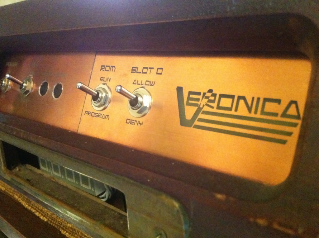
First things first. If a computer has a case, it needs a badge on that case, right? I figured it was time Veronica had her own cool 1980s computer logo. Here’s what I came up with:
For best effect, look at it while imagining Wham wearing zebra-print spandex and rocking out in a New Coke commercial. Picturing it? Good. You may proceed.
I stalked eBay for a long time looking for the right Philco, and when it came along, I pounced. The trick here is getting one that you like, and also one that is the right size. They usually don’t list the dimensions in the eBay ads, and that information proved difficult to find online. Some of the eBay listings do have measurements, so if you read enough of them, you can start to cross-reference the sizes. The website PhilcoRadio is a great resource, with wonderful photos of every model ever produced. You can usually deduce dimensions from similar models built on the same chassis using the information from that site.
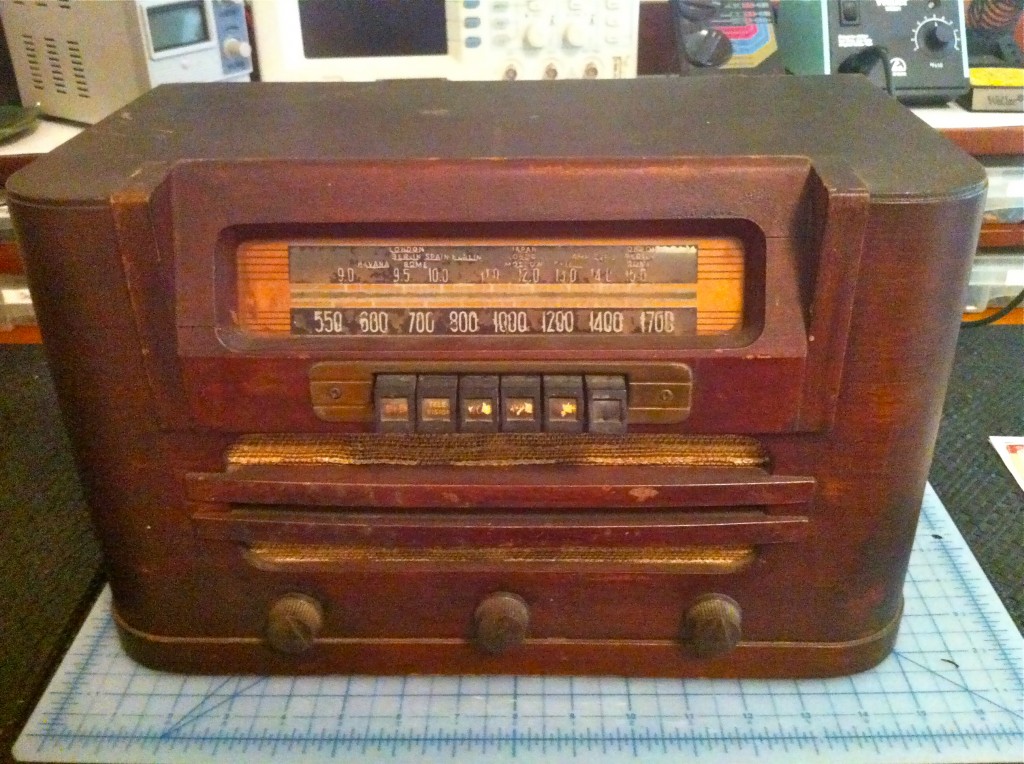
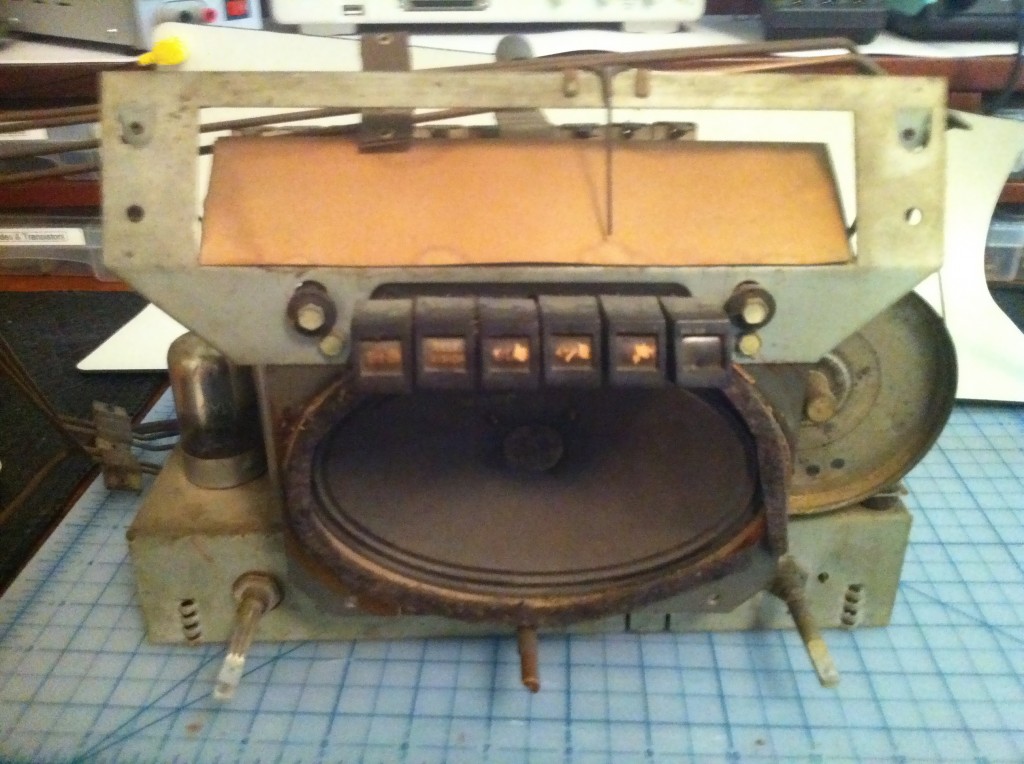
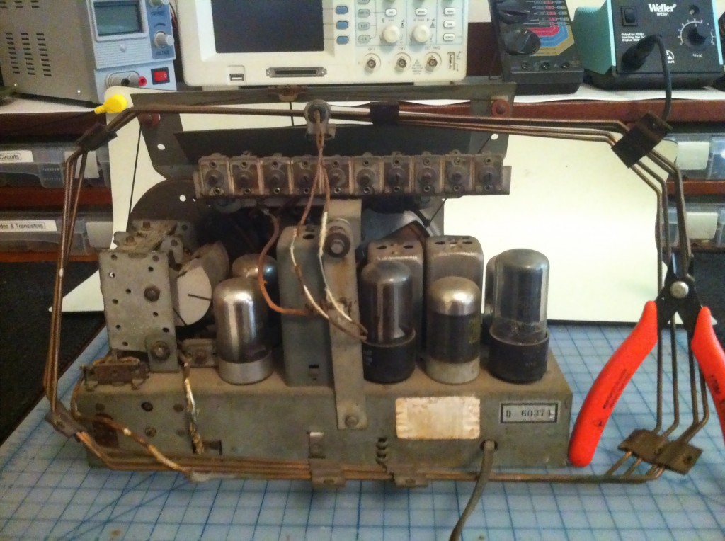
Now here’s where it gets really interesting. I think this thing really epitomizes the technological shift from mechanical stuff to electronic stuff. The mechanicals are fabulous, but the electronics are…. for lack of a better word…. amateur. Okay, okay, they get a lot of slack because Nineteen Forty Two. Someone probably listened to reports about D-Day on this thing. Still, it’s neat to see the contrast in sophistication with today’s electronics.
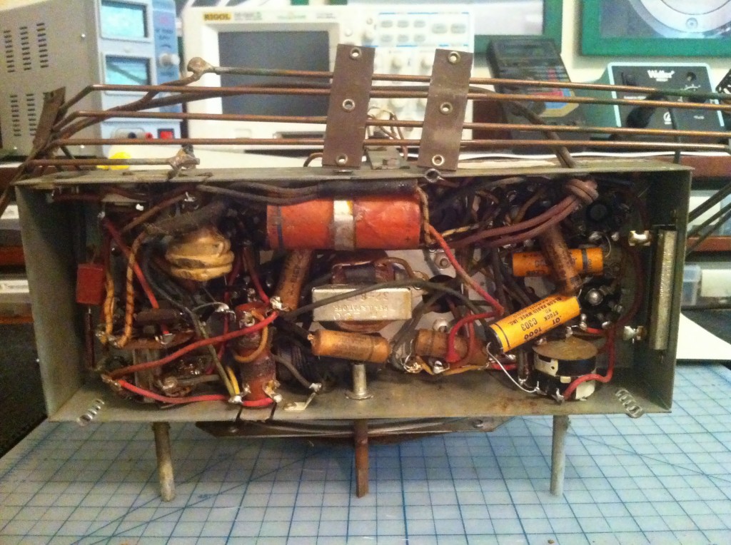
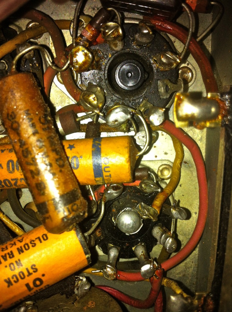
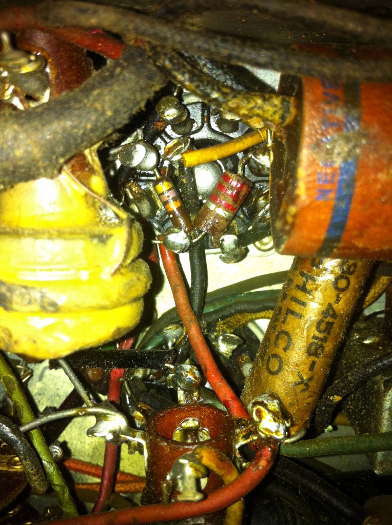
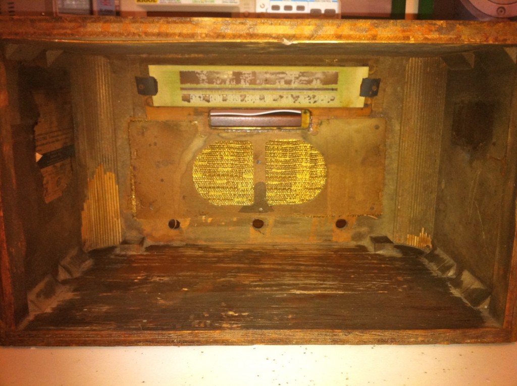
After deciding I wanted my control panel to go where that glass tuning display is, I had my second flash of inspiration for this project. I realized I can etch the control panel as a PCB! It will be sturdy, easy to make, and the resulting copper colour will compliment the old radio perfectly. Huzzah! Okay okay, this idea is hardly original either, but let me have this one.
So, with that plan in mind, it was off to the drawing board. I took measurements from the glass panel, fired up Inkscape, and came up with this:
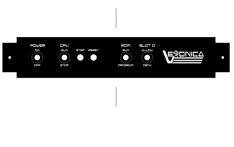
The font I’m using there is called Android Nation, and it’s by Nate Piekos. He makes great free-to-use (and paid) fonts. This one has the perfect 1980s look for our 1980s computer. If you’re interested, here’s the SVG vector file, and the PDF I generated to etch with. One trick with this is that the panel is almost 11″ wide. I don’t have any copper boards that big! You can buy them in large sizes, of course, but they’re expensive and I wanted to use what I have on hand. I split the panel in two and arranged it to fit on a standard 4×6 PCB. There will be a seam visible, but I figured it would be minimal. Besides, I will probably be making another one of these later, as I add or change controls. That’s the nice thing about this approach- it’s easy to change something in the SVG file, and just re-etch a new panel as needed.
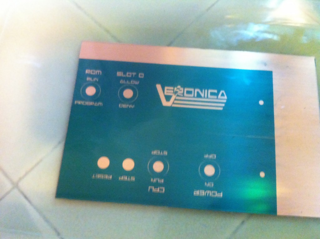
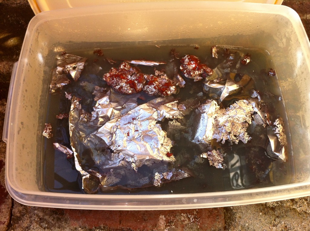
Let me take a quick sidebar to talk chemistry. Etching this board required quite a bit of solution (using my usual process), so I got to thinking about disposal. Some commenters on Hack-a-Day suggested that dropping aluminum foil into the used solution neutralizes it by (I believe) precipitating the copper back out. I couldn’t resist trying it.
Okay, enough faffing about. Back to business.
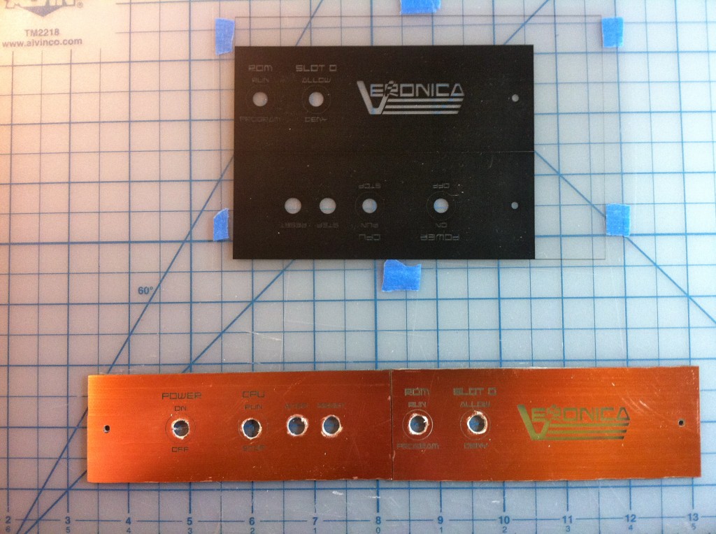
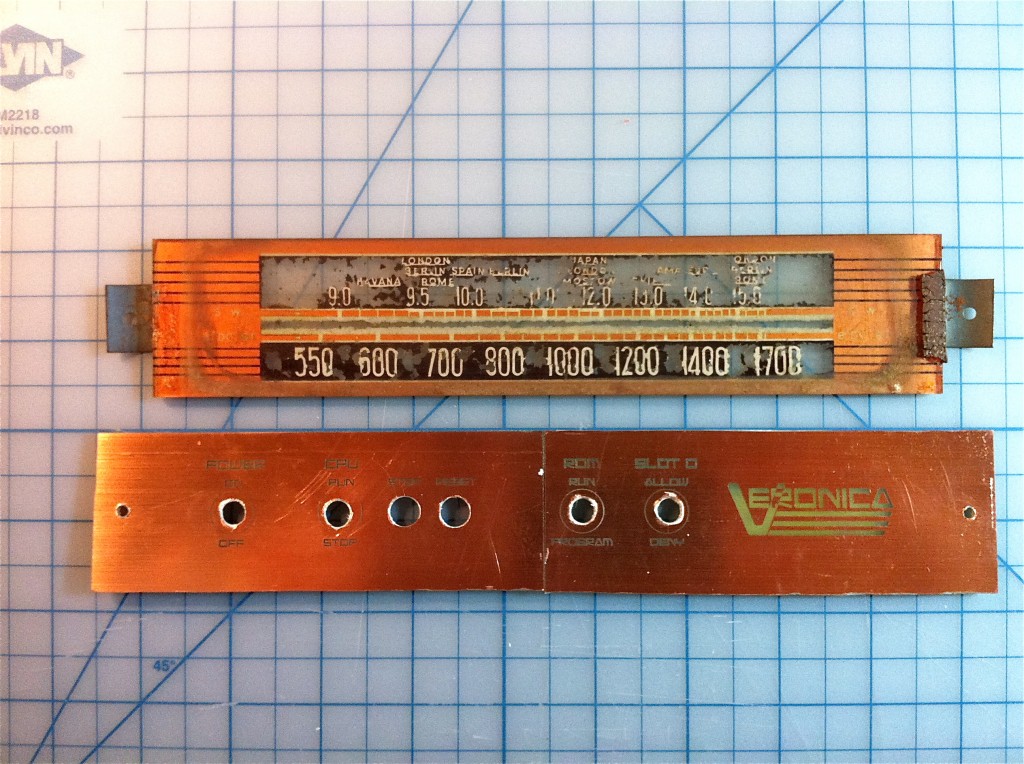
As you can see, the seam turned out to be more visible than I had hoped. The factory-cut edges of the PCB don’t actually have copper flush to the very edge. I suspect that’s because some large guillotine machine is hacking them out of larger sheets. If I’d known the seam would be this visible, I would have worked it into the design better. It’s in a bit of an awkward spot here. Next time!
Okay, time to wire up this chica. The controls include all the ones I’ve been using on my test rigs up to this point. Left to right, they are:
- Main power
- CPU Run/Stop (1Mhz clock or single-step clock, respectively)
- Single step (push button)
- Reset (push button)
- ROM Mode. In Run mode, the EEPROM is used as ROM. In Program mode, the on-board EEPROM programmer is activated.
- Slot 0 Allow/Deny. This is sort of a workaround, because the EEPROM programmer needs the system bus to itself during programming. Someday I’ll have a full bus arbitration circuit of some sort, which will make this switch unnecessary.
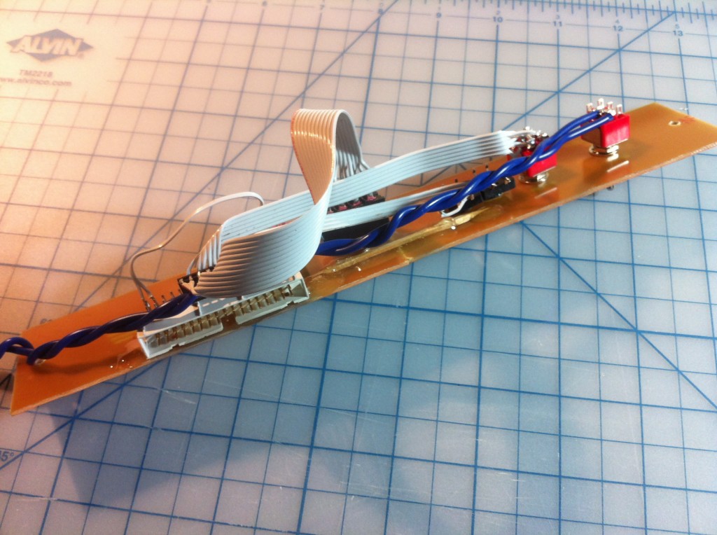
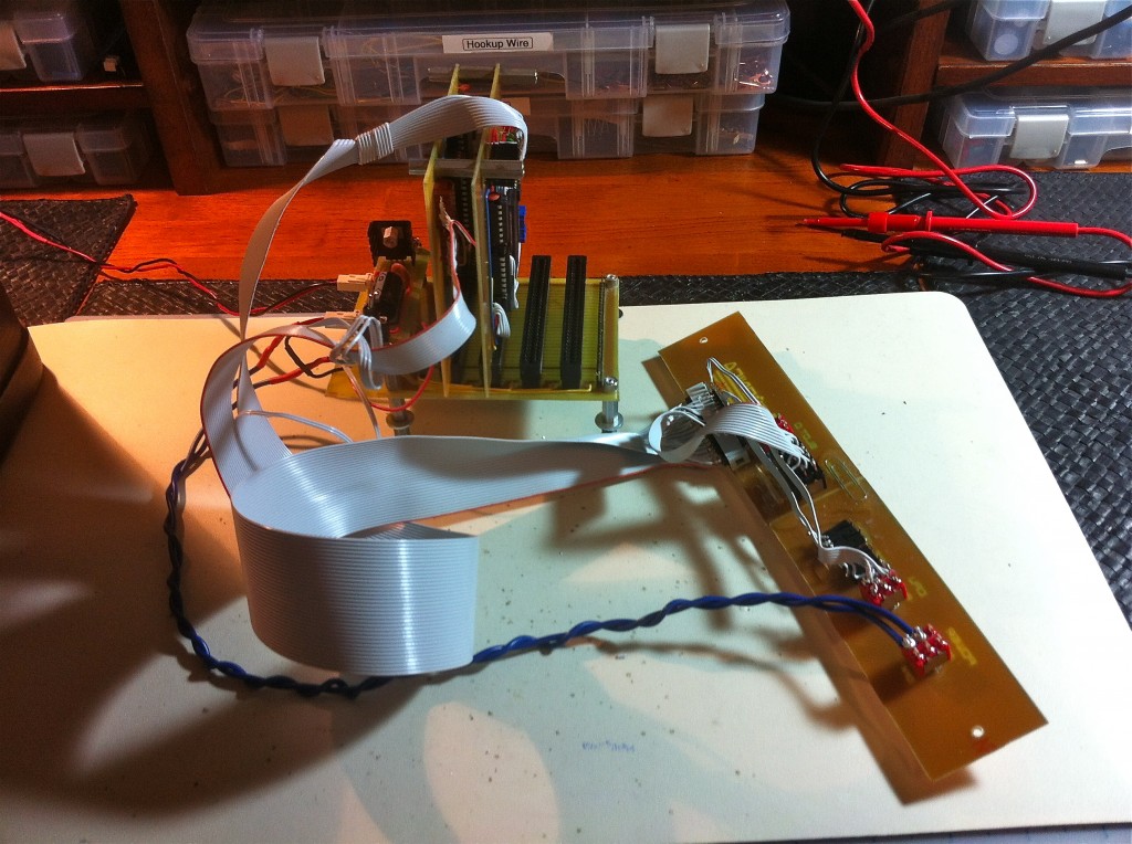
If you’re really paying attention, you may have noticed Veronica seems to have lost weight. I’ve been making noise for a while about cutting the extra PCB off the backplane, and I finally did it. It was needed to make the case work out the way I wanted.
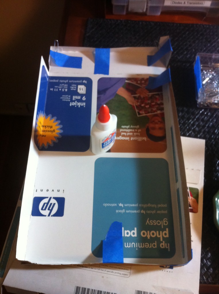
One last detail to take care of. The radio I bought was missing the back panel. I wanted something light and easy to modify that would serve to keep the dust out. I ended up making one out of an old printer-paper box. There’s something poetic about this, since I’ve sworn off owning ink-jet printers. I no longer wish to be locked into their scam ink economy and fly-by-night drivers.
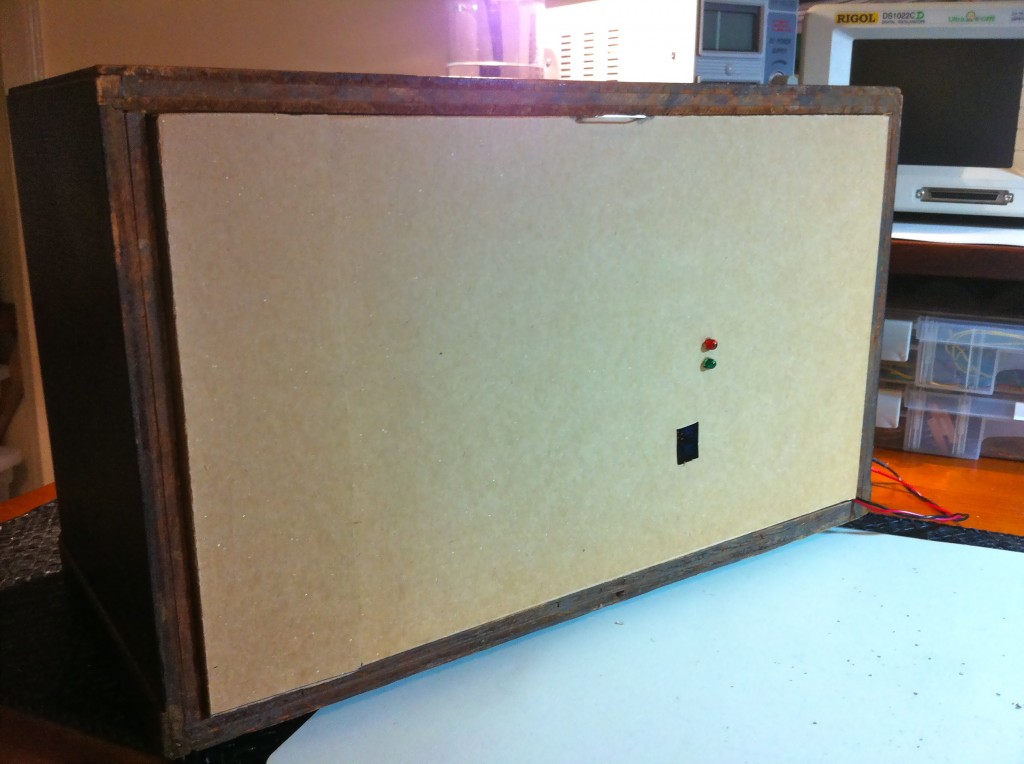
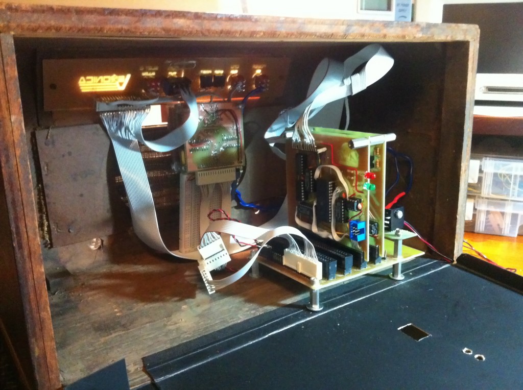
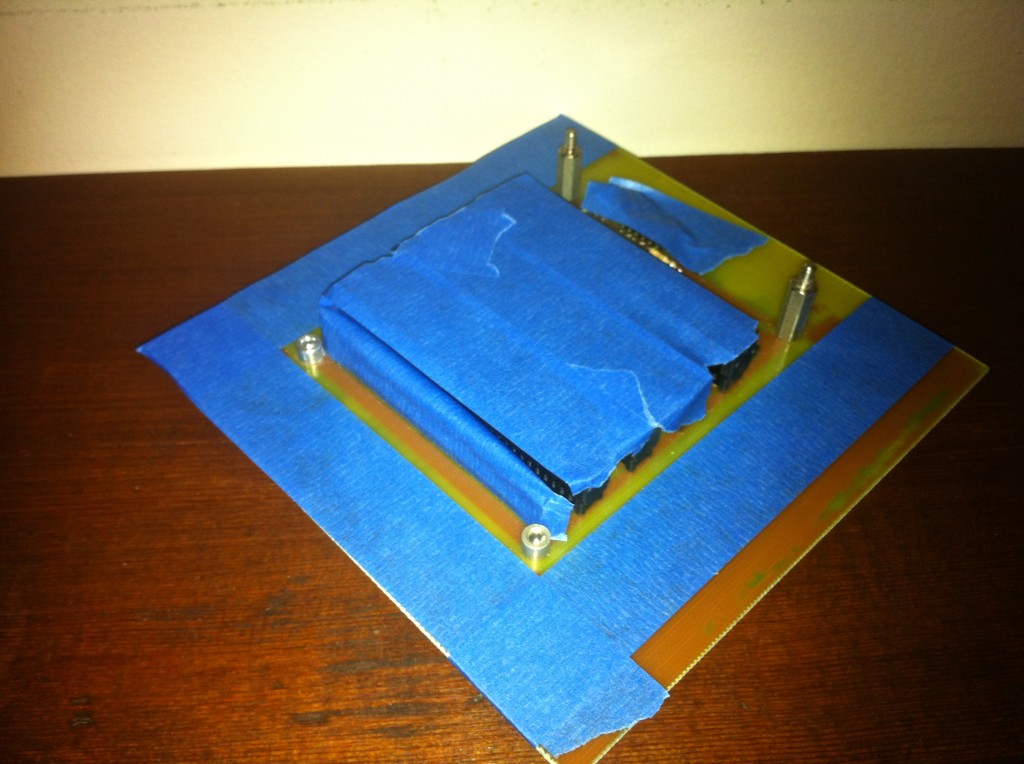
In that photo, you can see my third and final flash of inspiration on this project. The holes in the bottom are drilled large enough to fit an entire standoff, not just the screws. See those washers at the base of the standoffs? There’s another set of standoffs screwed in under those, sitting in holes in the case. This gives me the best of both worlds. For casual use, they are secure as-is and allow easy removal of the PCBs for development. For serious transportation, I can put screws in the bottom to hold those standoffs in place from the bottom. Simple!
Also, note how light shows through the etched portions of the control panel. That’s just screaming for some LED illumination, isn’t it?
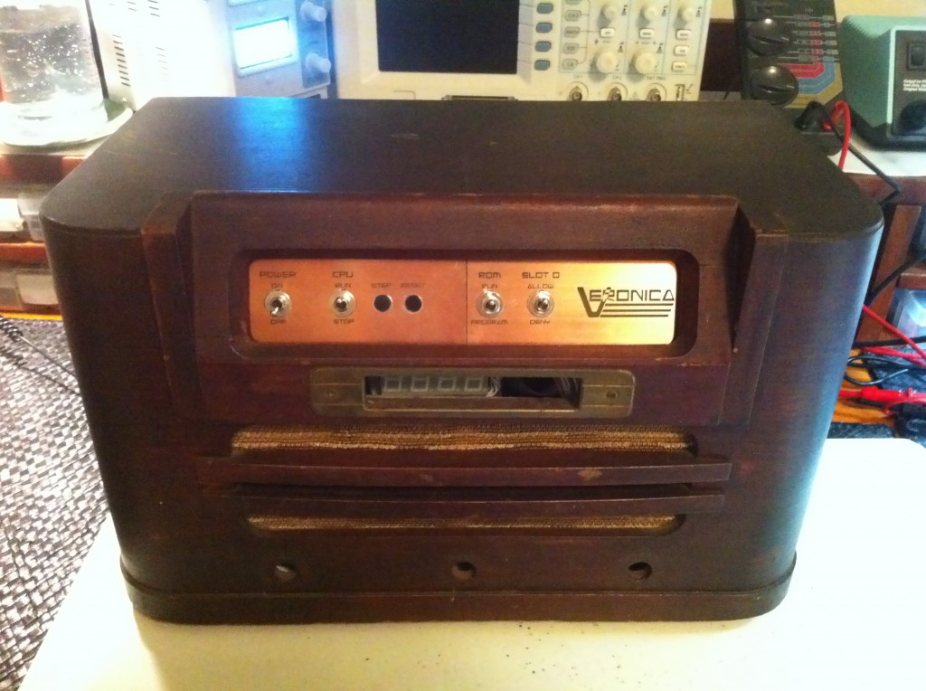
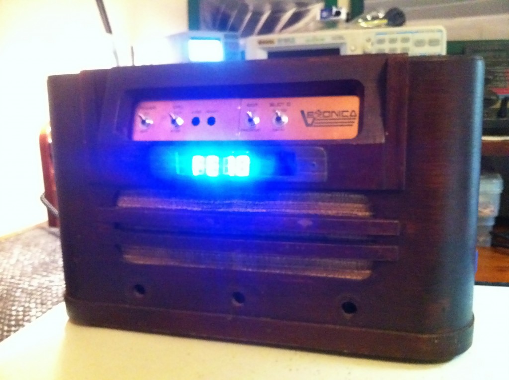
Well, this is exciting! I’m finally all set up to do some more electronics on her again. This was a lot of work, and many nights of waiting for glue and paint to dry, but it really needed to be done to start making forward progress again. I hope you enjoyed the ride!

Dare I say how awesome this is. Also, it looks like it should take….wait for it….cartridges!
Hah, you’re right, it does look like a perfect cartridge slot. They’d have to be smallish, like Atari 2600 size. A Nintendo or Sega size wouldn’t fit. Not sure if Veronica needs a cartridge slot, though. Hmmm…
Congratulations for your retro box 😀 I love your work, I’m a big fan of you and I hope to see more entries and progress on Veronica.
Thanks for sharing and doing a great work on documentation.
Looks greatly anachronistic 🙂
In fact I was recently thinking about electronics in an anachronistic setting and came up with the name ‘anachronics’ for the concept. I think it fits here too actually.
I see nothing wrong with the pictures, just the same awesome circuit pr0n as usual, and a bit of retro added. Yes that really is how they made electronics back then: they just had a factory with a bunch of people (usually women, they have smaller hands so they can reach stuff easier and work faster) putting these together day-in-day-out with big honking baseball-bat-sized* soldering irons. I had a tube radio from the 50s or 60s and it looked just the same as yours. The difference is that mine was mostly dusty inside and yours looks positively grimy. I wonder if yours was used in a kitchen or a car repair shop or something.
Just wondering: if you would have known that you’d be putting Veronica into an old radio case that previously had dead-bug circuitry in it, would you have dead-bugged Veronica? 🙂
By the way, that blue display looks completely out of place if you ask me. Old radios should have a warm yellow glow 🙂
Keep up the good work!
===Jac
*Well, that’s an exaggeration but they were much bigger than you average soldering iron today…
Yah, the blue is no good. If I do put a display in there, I think I’ll go red, because it would be more 80s. I could also shoot for 70s with a vacuum fluorescent display. Yellow would suit the radio nicely though, you’re right. Do seven segment displays come in yellow or maybe orange?
And, no, I would not deadbug Veronica. 🙂 My Mintzilla project is about the most complex thing I would do that with.
Oh, that is just screaming for some nixies or numitrons for the display!
yellow! yellow!
Oh yeah, I was just recommending that on HaD – go for numitrons, no high voltage required and the orange warm glow is priceless. You will need to equip every segment with diode if you’re going to multiplex it, though.
Numitrons (look for “iv-9 numitron” on *Bay) are a few bucks each, definitely affordable, and great fun!
Use Green led’s. Radios from that era often had “eye” tubes for tuning indicators and they had green targets glowing so that color would fit in. BTW the guys on the old radio groups will probably come down on you for this, but at least you picked a less valuable example of Philco to use. Nice work on restoring the wood work btw.
Yah, I was a bit concerned about stripping a valuable one. My budget works in my favor here. The rare/desirable Philcos, like the floor models and the famous Cathedral style go for big bucks. This model is common and working models go for under $30 US. I think I paid $15, but got burned a bit on shipping, because it’s actually really heavy. The wood is thick and the internals are all metal!
Oh, and actually, I didn’t touch the wood. It has a nice original patina on it that is quite fetching. I just cleaned it up and scraped down the interior a bit.
BTW Philco made quite a few radios based on the same chassis.
http://www.philcoradio.com/gallery/1942a.htm
The ‘point to point’ wiring technique was the way all radios and TV’s were made until printed circuits became the norm in the 1960’s as a cost cutting method. Until then all sets were wired by hand. Military and more expensive civilian electronics used ‘mounting boards’ or ‘tie strips’ for all wire lead parts (you can see examples of ceramic mounting boards with silver solder terminals in old tube type Tektronix scopes). The better sets looked like the assembly layout followed a well thought out plan, but the cheaper sets were wired ‘any old way’. Sets that covered short wave bands had to be wired more carefully to avoid alignment nightmares.
Zenith kept bragging about their hand wired chassis until they were dragged kicking and screaming to use printed circuits as well to compete cost wise with everyone else.
Awesome case. I must admit, before I got to the pics of the control panel I was secretly hoping for some touch-sensing circuit trace buttons. That would be awesome. Or something like this, and keep/mimic the original glass style! http://wp.me/pk3lN-eql
You should probably go easy on the electronics production. Remember, at that time the pros who usually assembled Philcos were probably soldering radios in bombers. If your radio looks like it was soldered by a noob, it’s because it probably was. 🙂
The mechanical buttons and pulleys sound awesome.
Very nice work! (And this is coming from someone who collects these old radios!)
As for the radio chassis itself, don’t part it out! You can bring this beast back to life by replacing ALL of it’s original paper capacitors (including the large filter e-caps). Once fixed up, these really do sound nice, and I see no issue in finding an empty cabinet to put the chassis back into.
That’s a good idea, Cliff. It might be a fun project. I wonder what I would listen to, though. I honestly don’t listen to radio except in the car when my iPod battery is dead. I’m a podcast junkie. Maybe I can make it play those…
Nice, really nice.
So how about this one: you might put in a green 7 segment display, put a thin weathered piece of glass in front of it and i think the pcb material will let some light throug [copper etched away] so you could put some green leds behind the logo and text.
anyway this was a nice read, again
grt
This is where it gets fun, AM radio signals travel pretty far at night. Sure it may be talk, but there’s a couple of good music stations (650 WSM, 1130 KWKH, if you’re into country). You can also find something like a Talking House (which transmits on the AM band) and pipe your iPod into that, or even make your own AM transmitter (many designs out there)
>I honestly don’t listen to radio except in the car when my iPod battery is dead. I’m a podcast junkie. Maybe I can make it play those…
Yes, that’s what I do with my ‘radio’ – it’s basically a FM receiver for my iPad. If you want a powerful consumer transmitter, the only option out there is the C Crane (read the amazon reviews for the internal potentiometer transmitter boost hack). You could even automate turning the radio on and off from the iPhone (Arduino + AC relay, etc).
I’m enjoying this series. I encourage you to keep going, and hopefully there’s enough interest for you to get a book deal out of it if that’s what you want. Cheers.
Maybe a piece of dark lexan in front of the 7-segments? There’s always this idea, maybe in amber? http://hackaday.com/2012/02/18/edge-lit-nixie-tube-is-sheer-brilliance/
Awesome work on the project… having seen (and used) some wire-wrapped micros in the 80s I think you’re doing an excellent job.
Your comments about the construction of the Philco are interesting.
Electronic devices from that era are pretty mechanical looking… keep in mind that PCB style construction didn’t really happen in a big way until the 50s.
Also, until quite recently, it was easy enough to find someone to repair one of these devices cheaply enough to avoid buying another one (so some of the mods you mention may well be after market).
You asked if all 1940’s era electronics was built that way — the answer’s yes. Your stuff is original, the voltage divider isn’t a ‘hack’, that really is how it was done back then. Cool, eh?
Very cool indeed!
I’ve taken a few photos of the inside of a valve (vacuum tube) oscilloscope, here:
http://www.flickr.com/photos/anachrocomputer/sets/72157629671778013/
Actually, the interior shots are of the plug-in module that is the Y amplifier section. It’s all made by hand in a similar way to the Philco radio. The scope is a CRT storage-tube type, made in England in the early 1970s.
Nice shots! Thanks for sharing. That’s actually quite pretty inside. Looks really well made, considering the technology level. I love the modular structure, and the insulated leads on some of the components. Very posh.
What do you think 100 years into the future an archeologist would say when they found this device? It would be so confusing to them that it would screw up their entire mindset of our technology. Just a thought!
I didn’t catch the make of that old radio but the mix of Octal and Loktal tubes cry out Zenith or Philco. There is a project out on the web someplace (www.mightyohm it think) on how to build an internet radio by hacking a wireless router that would go well with that radio. Just restore the audio section and pipe the output of a USB sound ‘card’ into it. Only do get an isolation transformer to power the ‘hot chassis’ radio!
Your logo reminds a bit of the Commodore 64 logo with its rainbow-coloured bars. And there is, originally from the 1960’s, Radio Veronica, which have kept their logo pretty much unchanged over time, as far as I can tell: http://www.veronica.nl/ . They also do tv since quite some time.
Thanks! That’s exactly what I was going for. Seems like all the 1980s computers had logos riddled with primary colours. Color was associated with computing power, because it was a pretty big deal for a home computer to do it at the time. Everyone wanted to convey their platform as powerful, so crazy pointless colours abounded in logos and promotional media. It was also kinda the style at the time, in pop culture generally.
Hi, just came across your blog from Hack-A-Day. This is some very impressive work you’re doing here.
Have you considered the possibility of using Veronica as a fuel injection controller for an engine? That way you can get into hacking something completely off the wall, like a 1940’s Ford flathead engine or some such. Something to go with the radio. 🙂
1. How about a card-edge connector for external expansion somewhere, a-la C64? 2. Translucent colored paper and a white LED for the logo to get the colours right? 3. The holes at the front are screaming for connectors… Power plug, serial, composite video? (A parallax Propeller would make an ideal graphics processor)
Interesting re-use of the old Philco!
However, take it a bit easy on the 1940’s.
While the techniques were fairly common, tabletop radios were at the very bottom of the electronic food chain. They were the poorest built and had numerous cost cutting measures, some of which would be illegal today because of their potential lethality, (no power transformer is the first to come to mind, tying one side of the power line to the metal chassis is another).
Meanwhile other gear, better built but using the same techniques, still work today.
The soldering frequently looking more or less like your photos.
A fair point. Since this was written, I’ve seen a number of more high-end assemblies from the same era, and you are quite right. Some are impressive indeed.
LOVE the project! I’m doing a modern PC build an a floor standing Philco cabinet, and came across your page. I did notice a number of people mention nixie tubes. You wouldn’t be able to really do hex using commonly available nixies, as far as I know (even though I LOVE the look myself), but VFD or Panaplex would net you a retro look, and give you Hex output. Never did look into if hex nixies ever were created, but I’ve never found one.
Me, I personally collect vintage calculators, and have a number with Nixie Tubes, CRTs, Panaplex Displays, VFDs, and LEDs. I’m certain you can find some fun way to display numbers, ranging from 1964 to modern machines, and I have parts from a 1961 tube calculator, and numerous mechanical models from earlier years. I think I’ve seen all but a couple display technologies.
As for display options, a completely homebrew option that would work, and served as one of the EARLIEST forms of number display, was layering thin panels of plexi on top of each other, with lights to edge illuminate them. the patterns of numbers were punched into the surface as a series of tiny dots. A bit of work, but ULTRA retro! 🙂
If you choose to go VFD, there are some nice cheap, and readily available Russian VFD tubes. VFD tubes use lower voltages to energize as well, so are easier to work with. The Russian ИВ-18 is a nice 8 digit tube with decimal points, as well as -, E, and • indicators on the left side, and measures 4.5 inches long, .75 inch diameter, with an active display area 3.25 inches long. The height of the characters is only slightly less than the tube diameter. It glows green.
If you are interested in more of a gas glow, something with that 50s era orange glow of neon… One option would be a panaplex display. Not too common, but if you want a complete package to hack, look for certain early 70s calculators. If you are willing to spend a bit, and have no fear of parting out a relic, go for an old Monroe or Victor or Compucorp calculator (there are more Monroes, so they are less rare, and less painful to part out, IMHO. Victors with panaplex… Heck, I collect them broken!). Look for the 1920/30 models, or the 300 series portables. They have neon gas 7-segment panaplex displays. The Compucorp/Monroe portable 300 series models are particularly impressive. These were key sequence programable scientific, statistics, or financial calculators the size of a larger portable 70s or 80s era audio cassette tape player that used 4 “D” batteries, and who’s display was a 16 digit neon beauty with 1/4 inch tall digits, and a width of 4.25 inches. These models are highly prized models, but are also VERY susceptible to static, so if you are willing to reverse engineer or build the driver for the display, you can sometimes find broken ones for cheaper than what good ones go for, and get a VERY impressive display out of it!
As for my own project, I myself plan to put a nixie tube clock in my PC, just because I always wanted one, and can’t think of a better place to put it! 🙂
My machine is far different from yours in philosophy, being a top of the line modern PC build (hay, I need a new computer, mine’s going on 9 years old now!). I picked up a gutted floor model Philco radio cabinet a few years ago, and never did use it. Now I have a project for it, and I’m very happy with the direction. As much as I LOVE the massive size of the cabinet, I DO still need it to be on a desk, so I plan to separate the foot of the cabinet from the speaker segment and cut that down, then replace the foot. It’ll still be taller than a traditional PC tower, and deeper, and wider! Space will never be an issue for me! Between the massive ventilation the speaker grille will provide, and all that open space, just imagine all the hard drives I can pack in there!!! Mwahaha!!! 😛
Oh! Idea… In regards to the colorful logos of the era… Look at your local hobby or dollar store. Sometimes you find these “stain glass” paint kits. It’s translucent paint that is used for fake stain glass. It’d probably fill the depression of your etchings perfectly. illuminate with a white LED (or a few) from behind!