Stand back- I’m going to try SCIENCE!
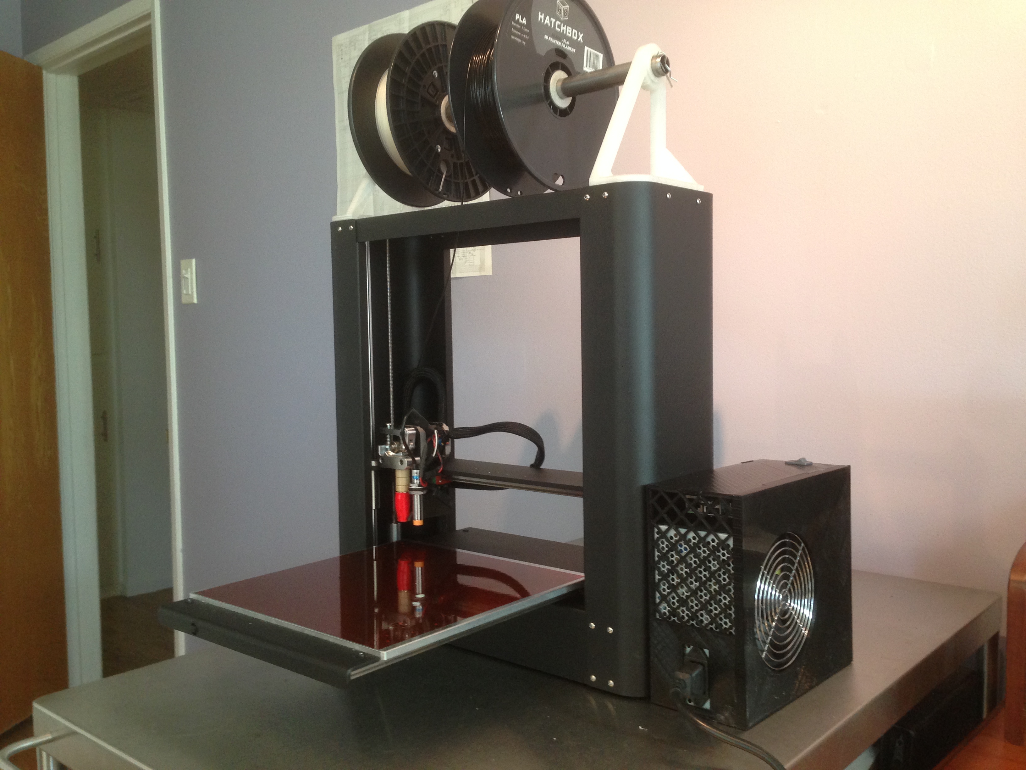
My PrintrBot has been chugging merrily away for me, and while it works, the preparation of the bed before each print is a real hassle. The solution is a heated bed, and it was high time to install mine.

PrintrBot’s instructions for installing this kit are pretty good, but as you might expect, I ran into a few gotchas.
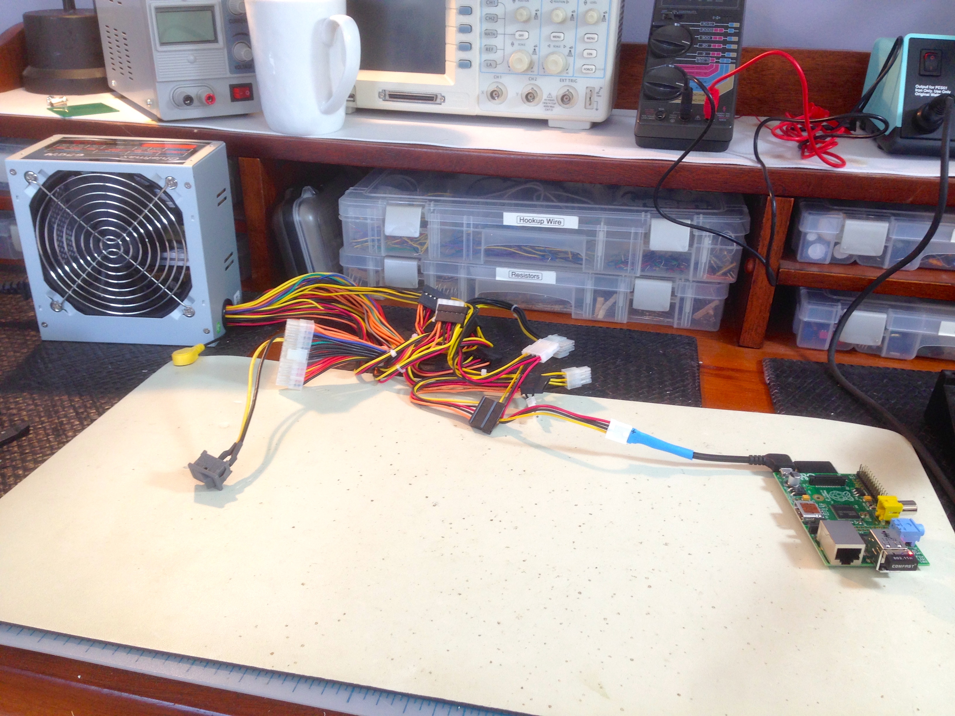
It’s important to note that the heated bed requires a lot of juice, and as such the PrintrBot’s commodity laptop power supply isn’t enough. It requires an ATX power supply. Any ATX supply with PCIE support will work. PrintrBot sells one, if you want to guarantee getting the right thing. No offense to PrintrBot, but Amazon sells equivalent or better ATX supplies for about a third of the price with free shipping. I opted for the latter.
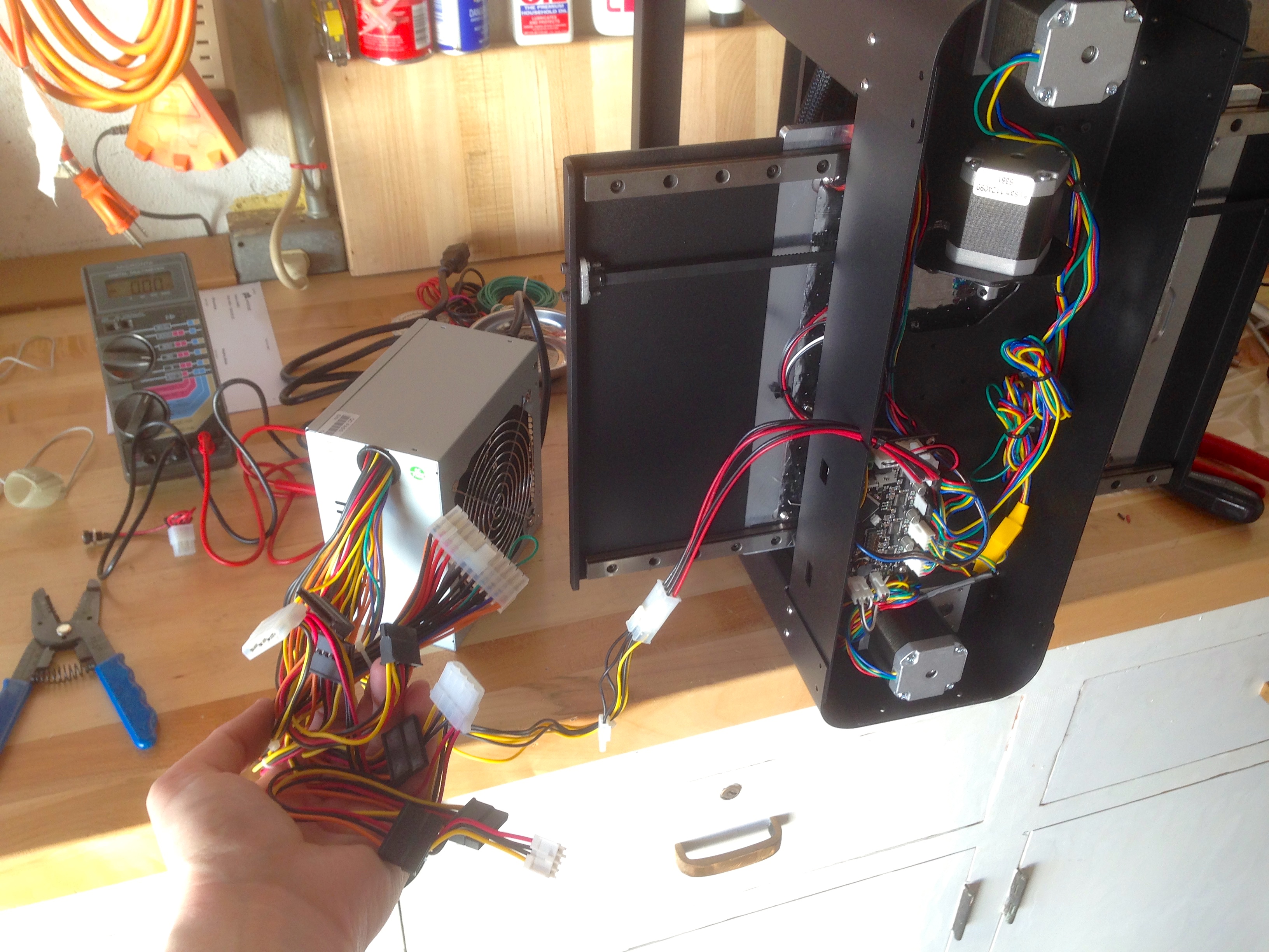
With all the parts in hand, refer to PrintrBot’s document on how to wire up the power supply. It can be tricky to identify the correct connector amidst the bewildering array of them on an ATX supply, but a voltmeter verified it. The PrintrBot wants 12V, so whichever connector fits that and delivers 12V is the one. Note that the connectors are modular, so you may have to separate a few to find the right one. The PrintrBot’s control board has a keyed molex connector on it just like the power supply, so there’s no hackery or guessing involved. There’s only one connector that will fit. Still- verify with a voltmeter to protect your investment. I was never a build-your-own-PC person, so ATX power supplies are pretty new to me. Apparently the yellow wires are +12V and the red are +5V, but I never trust wire colors.

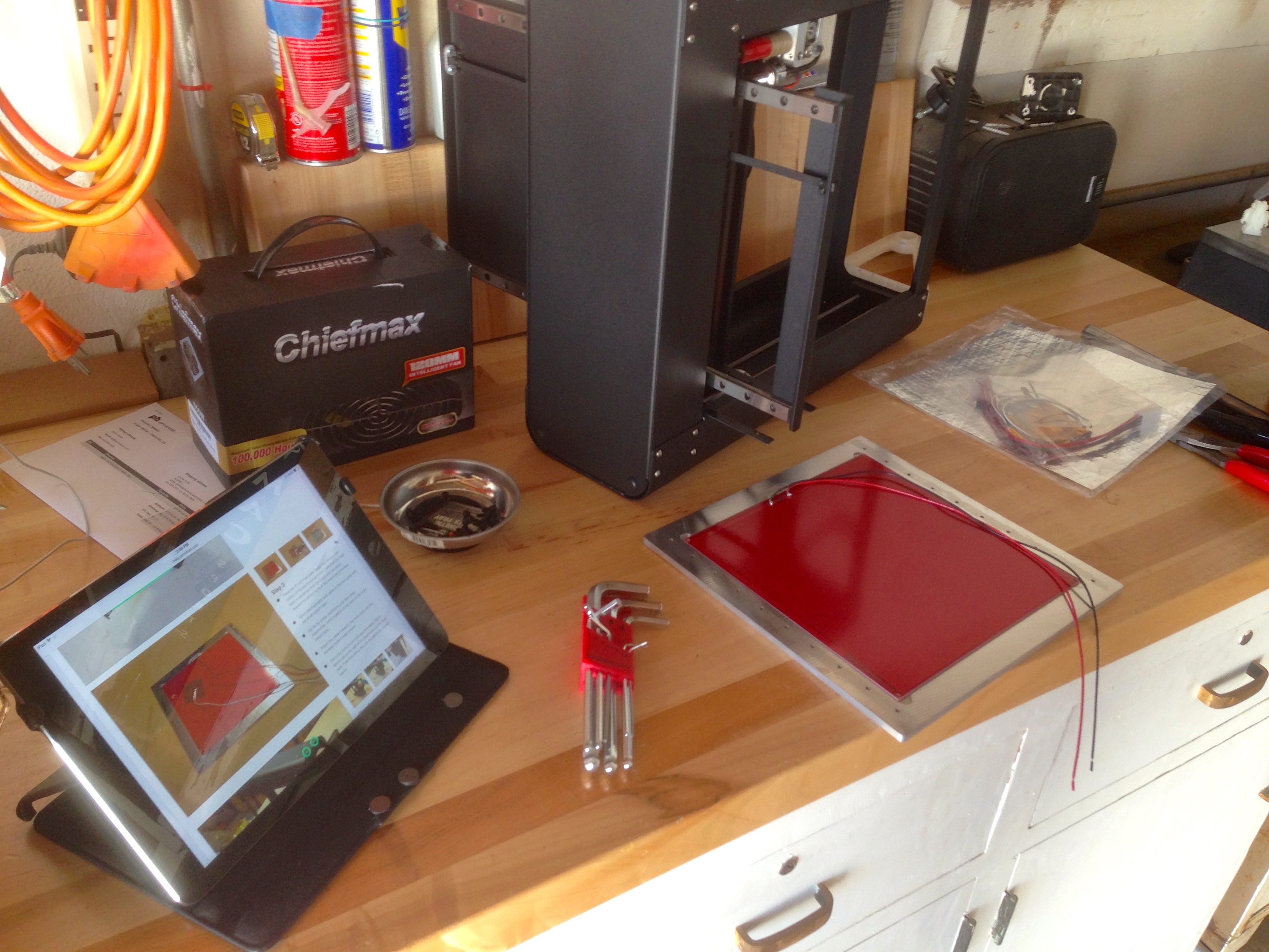
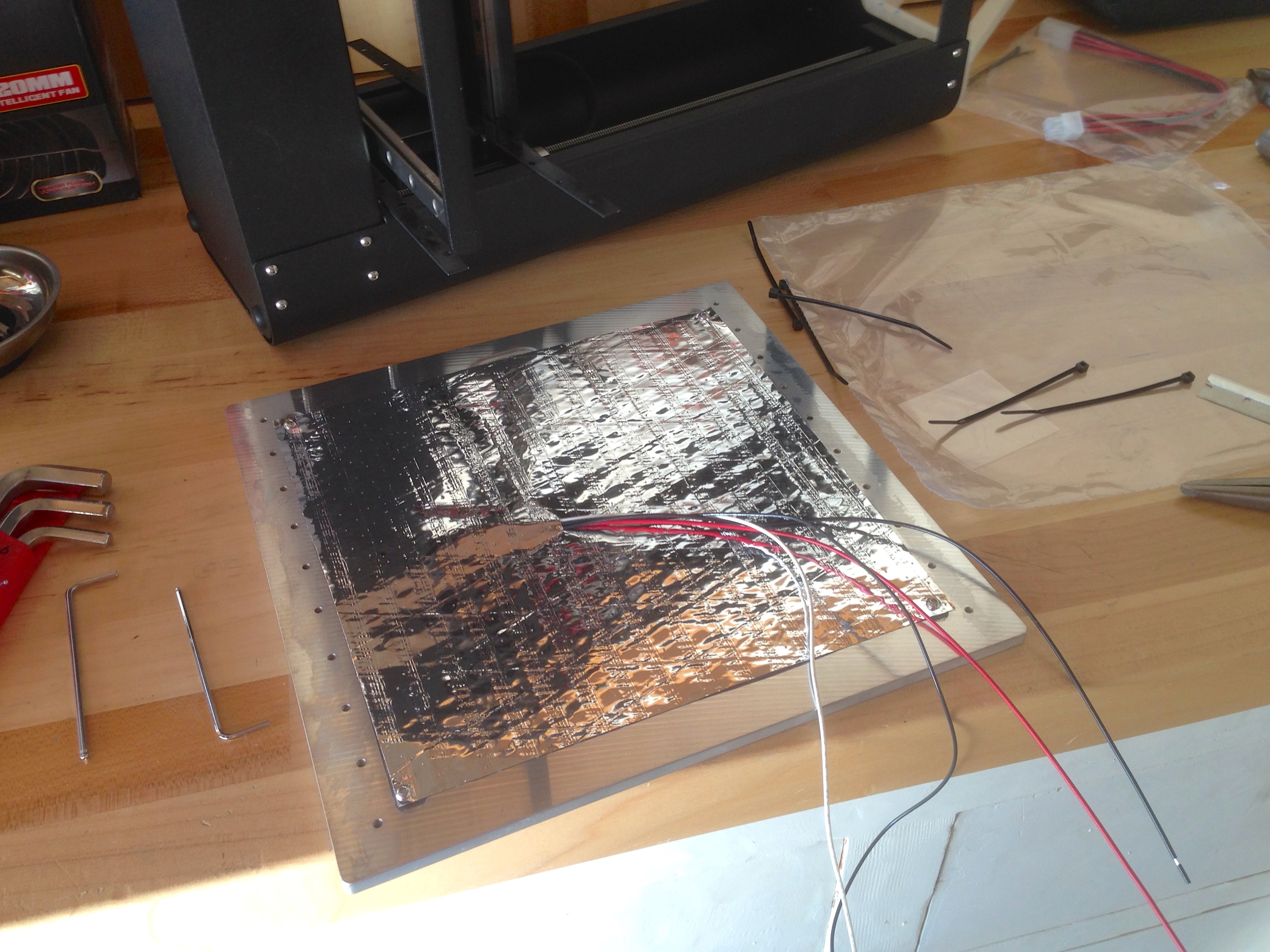
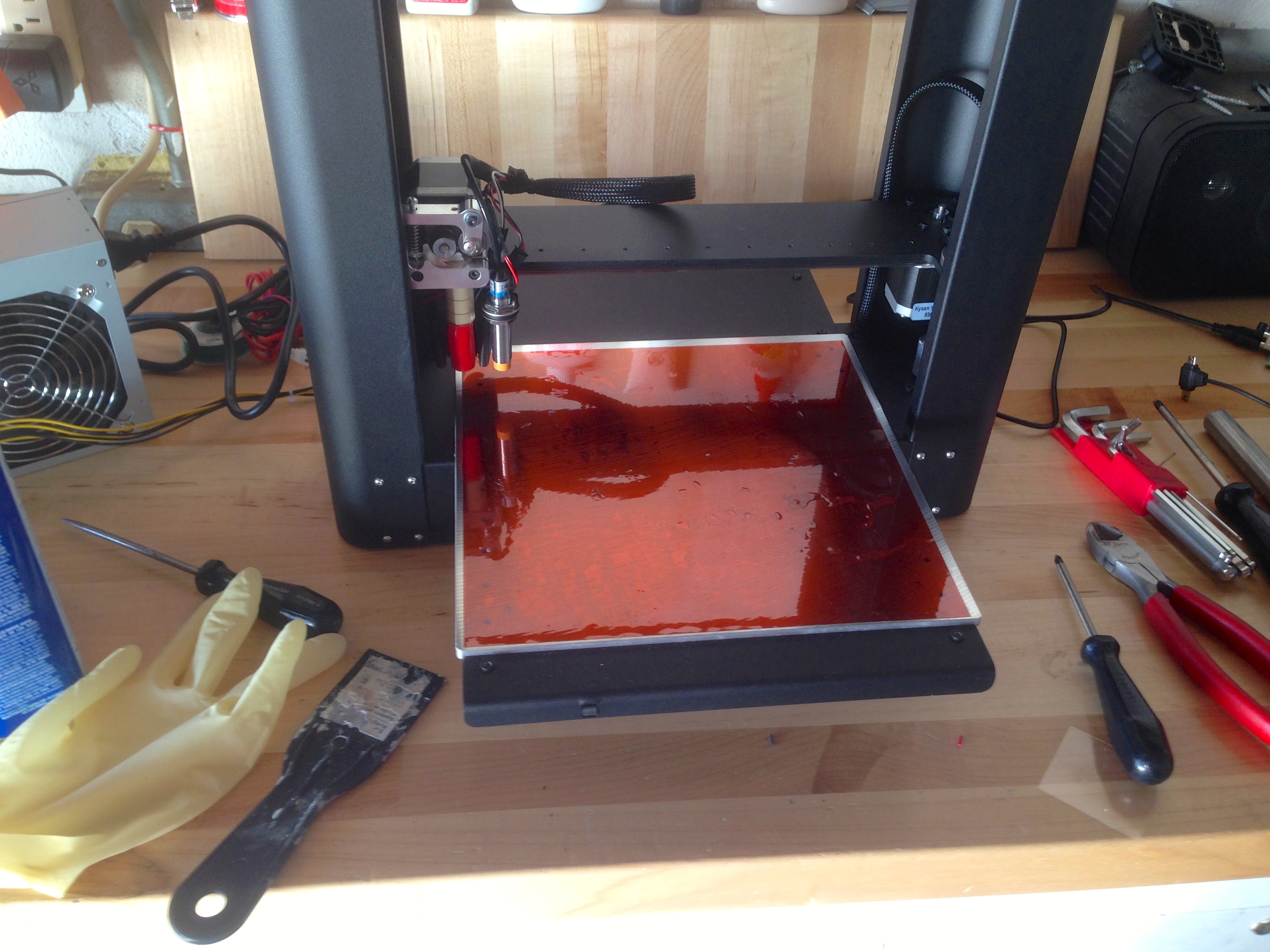
The final step is to apply the large square of Kapton tape to the bed. Here’s where the instructions let me down, and where I wish I had done a bit more homework. The instructions fail to warn how tricky it is to get this tape down without bubbles. If you get bubbles, they are very hard to remove. There are good techniques out there which I wish I had known about. If, like me, you get bubbles, they can be worked out with a plastic scraper and a lot of patience. A few small bubbles don’t seem to hurt too much, but it’s certainly better not to have them.
Now that the machine is running off an ATX, it seems silly for my Raspberry Pi print server (yay Octoprint!) to be running off its own USB power supply in a separate outlet. I poked around on the ATX with the multimeter, and found a convenient connector that delivers 5V for the Pi. All I needed was an adapter cable.
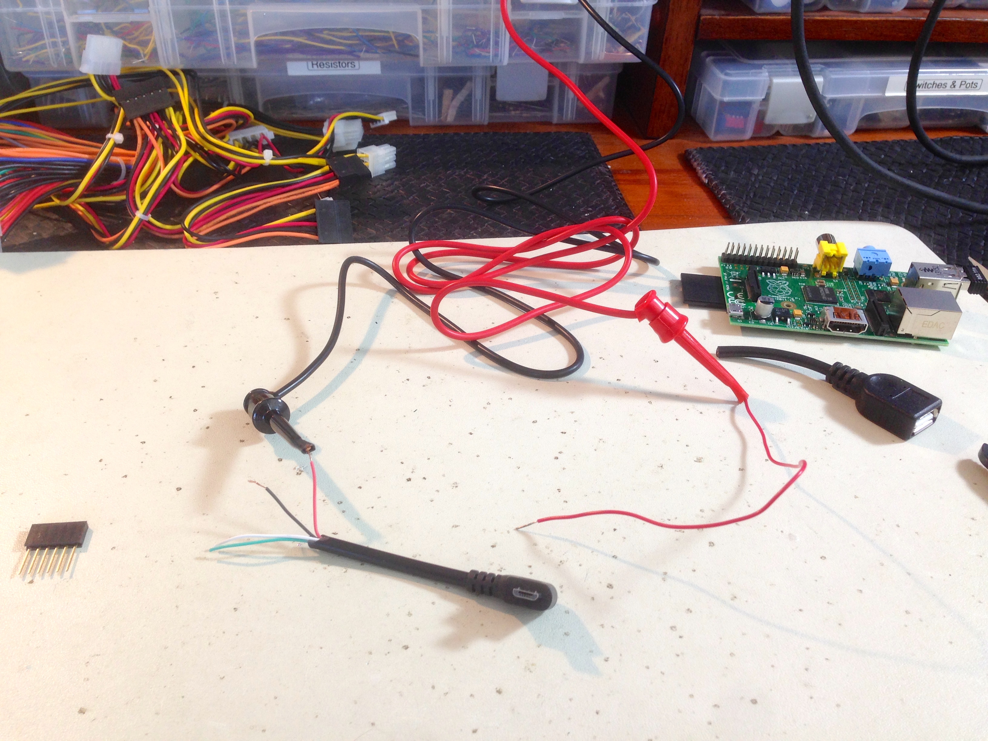
Once I had verified all the pins and wires lined up the way I expected (say it with me: never assume the wire colors are right), I grabbed a 0.1″ header and some heat shrink to make a little cable.

One oddity about the PrintrBot Metal Plus is that is has no power switch. I don’t like plugging things in and unplugging them to turn them off. Luckily, the ATX supply makes this easy. There’s a particular jumper wire required to make the supply turn on (as shown in the PrintrBot instructions), so it was easy enough to put in a switch there instead. Maybe that’s what the jumpered pins are intended for? No doubt all the custom PC people are screaming at their web browsers right now, enraged by my ignorance. Anyhoo, the junk pile produced a rocker switch from who-knows-where (an 80’s coffee pot, maybe?), and I wired it up lickety split. One caveat to this- since the Raspberry Pi is now powered from the ATX, turning off the switch kills the power to it as well. Technically, of course, you’re not suppose to kill power to a Un*x machine without shutting it down in software first. In practice, for something as simple as this dedicated Octoprint setup, it doesn’t hurt anything. If somehow a file gets corrupted from improper shutdown, it’s a simple matter to image the SD card again. There’s no critical data on the Pi.
The heated bed is pretty awesome, I have to say. It immediately and noticeably improved my prints, and not having to do any bed prep is awesome. I did find that I needed to tweak my calibration a little bit. Well, more than a little if I’m being honest. This is likely a combination of the heated bed and the fact that I hadn’t yet tried to print anything really challenging. My spool holder was pretty substantial, but it did end up with some warping from poor adhesion to the blue tape.
At first, my heated bed prints seemed to be coming out great. The small test box looked fantastic, with good precision, smooth sides, and sharp corners.
I then tried to print something genuinely large for the first time, and here’s where things got interesting. First things first, however. I decided to try making a case to house the blob of ATX-Raspberry-Pi-Switches-Etc that was now hanging off the side of my machine.
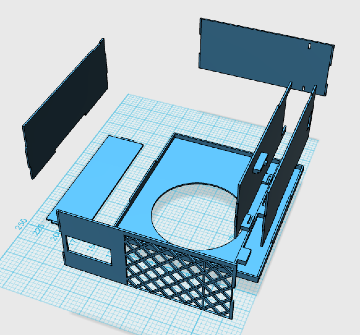
I designed a box that would sit next to the printer, and hold everything nice and tidy. Finding a model of the Raspberry Pi Model B (the one I happen to have) to use for designing the mounts wasn’t easy. Other Raspberry Pi models are plentiful. You can’t throw a rock at the internet without hitting a model of the B+, for example. Not so for the lowly B. I did finally find one, and unfortunately I’ve misplaced the link to it, so I’m unable to give credit where it is due. Thank you, anonymous donor! Allow me to pay it forward here.
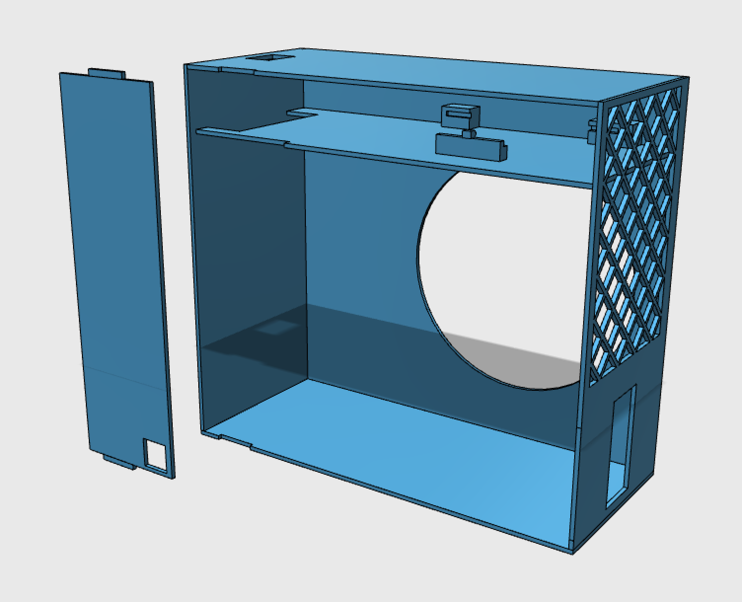
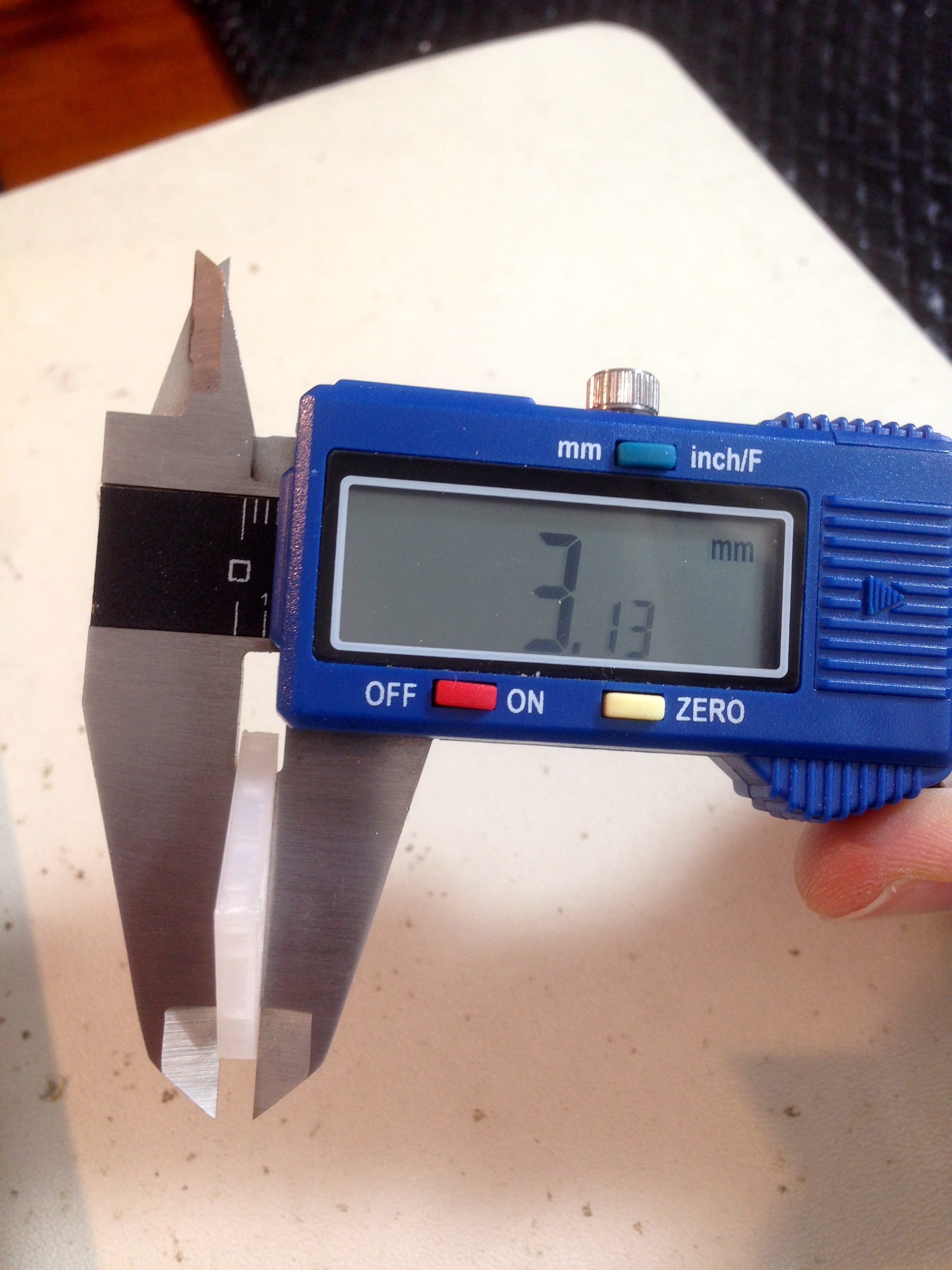
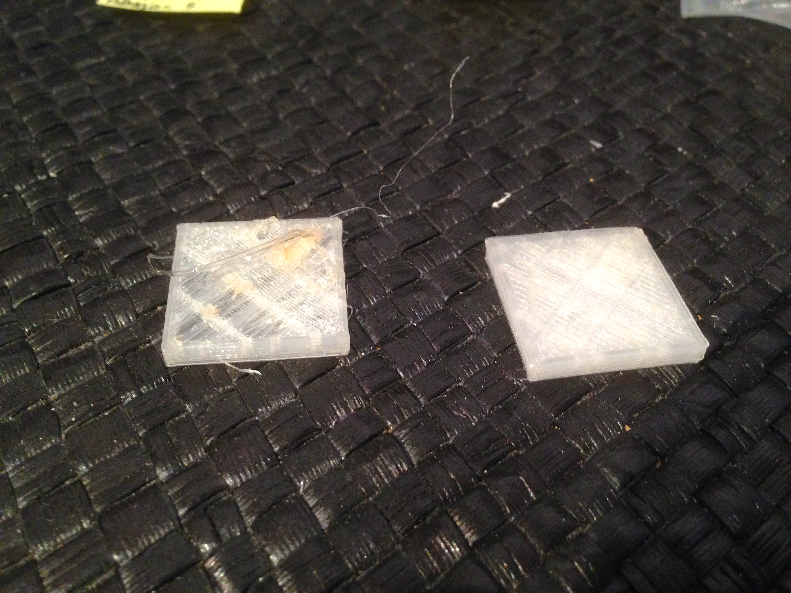
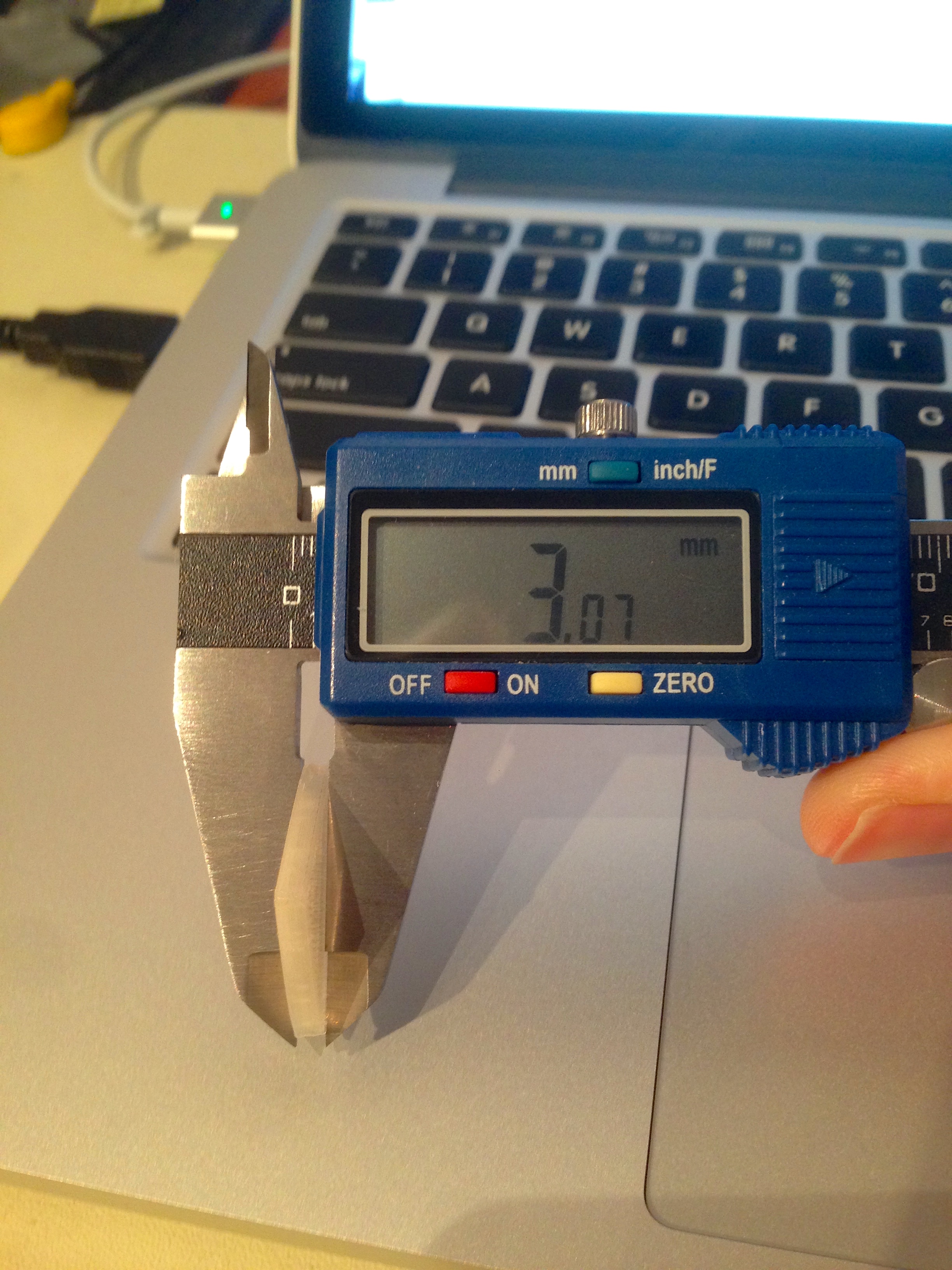
A print this large (it occupies most of the 10x10x10″ Metal Plus build volume) takes serious time to print. About 2-3 days, in fact. For that kind of commitment, I needed to know for sure the dimensions were right. To that end, I started by chopping up the model to isolate the areas where fitment was critical. Meshmixer is a great tool for this. Each of these little pieces could be printed in 30-60 minutes, so tweaking dimensions was easy.

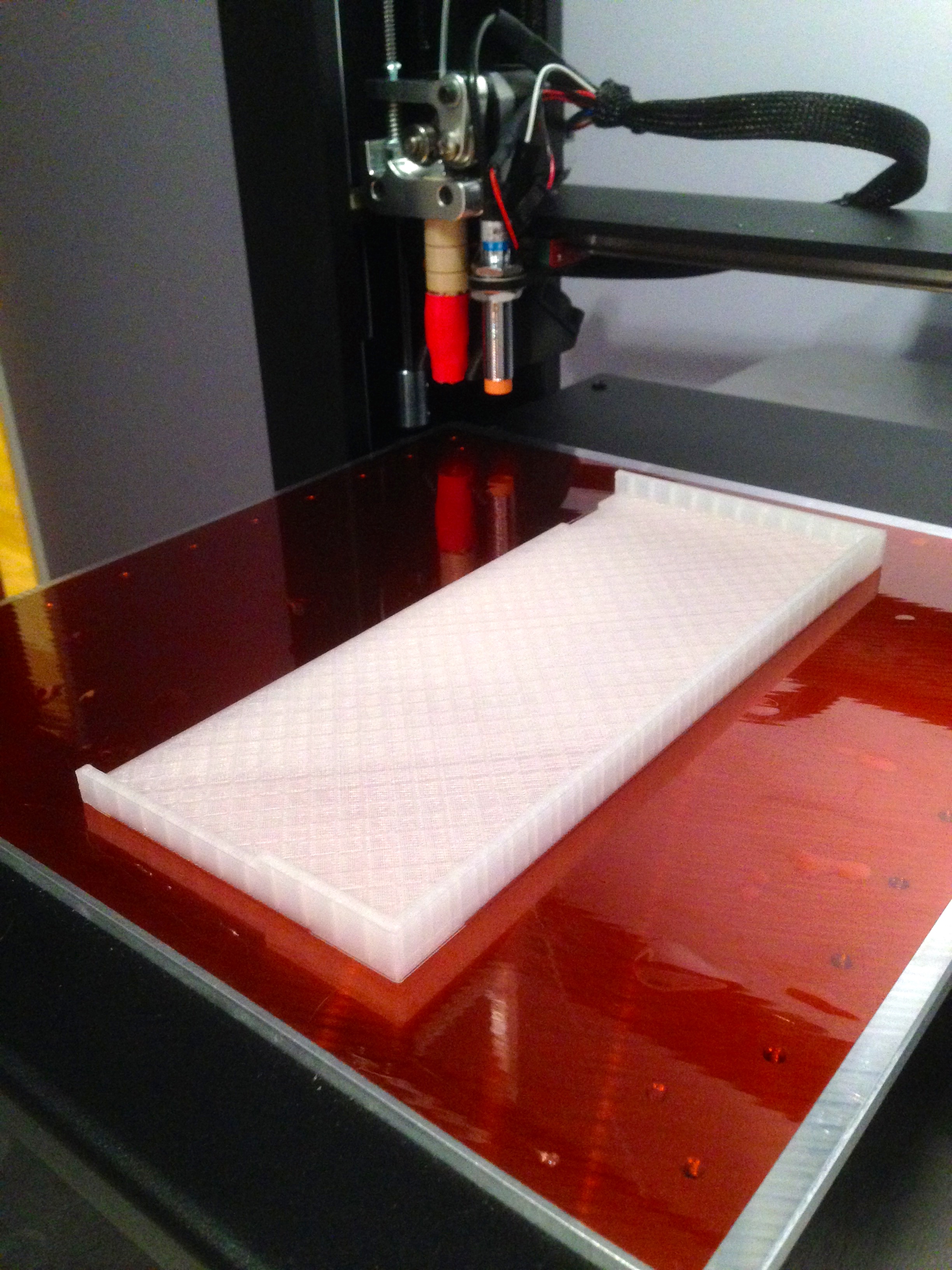
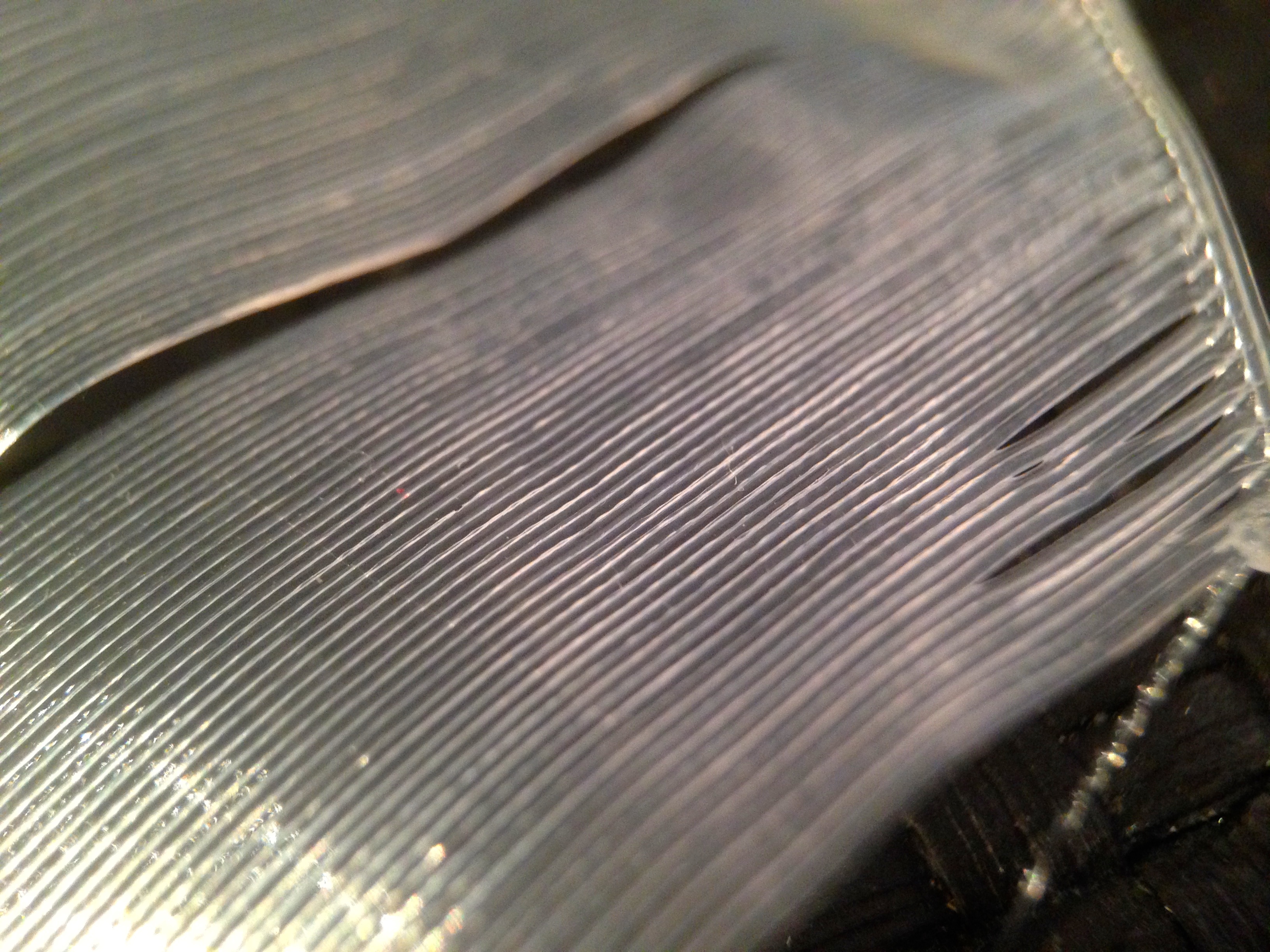
With all my dimensions validated and tweaked as needed, I pulled the trigger on the massive multi-day print. The large round hole for the fan is face-down on the print bed, so it starts by printing a very large flat surface. It was clear right away that this was not going to succeed. In a print this large, I could see my quality was not where it needed to be. The surface was stringy, clumpy, and pulling apart in different areas. No good. I hadn’t done any serious calibration of my print settings, but it was clear I now needed to. How would I know what to tweak though? There are a lot of variables, and I didn’t know what effect they might all have. Clearly, this is a job for science!
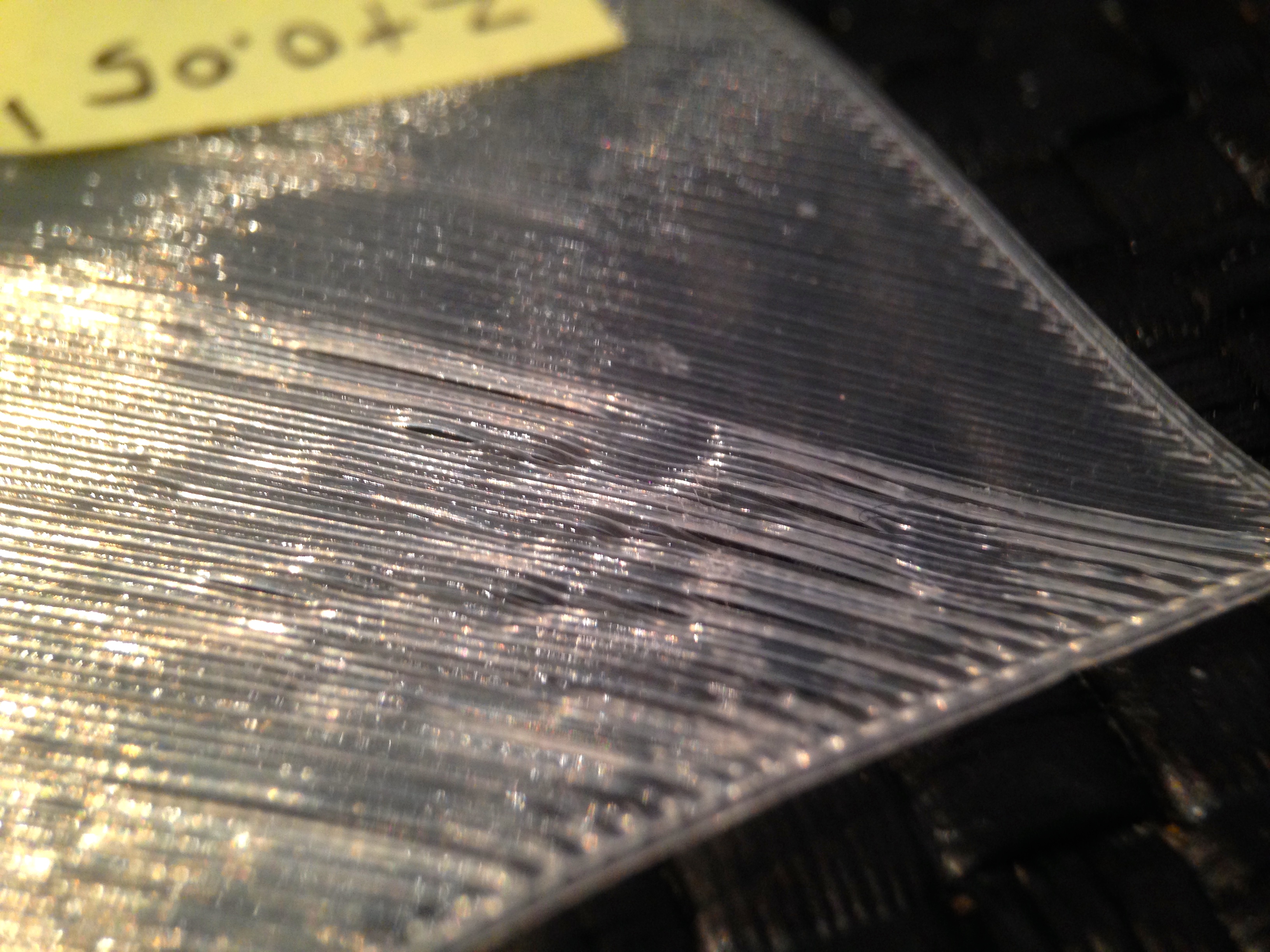
I set out to create a series of small tests, controlling one variable at a time, and carefully logging all the results. I experimentally controlled Z-home height, head temperature, bed temperature, and flow rate. These seem to be the variables that most affect print quality and bed adhesion, based on googling various kinds of 3D printing problems.
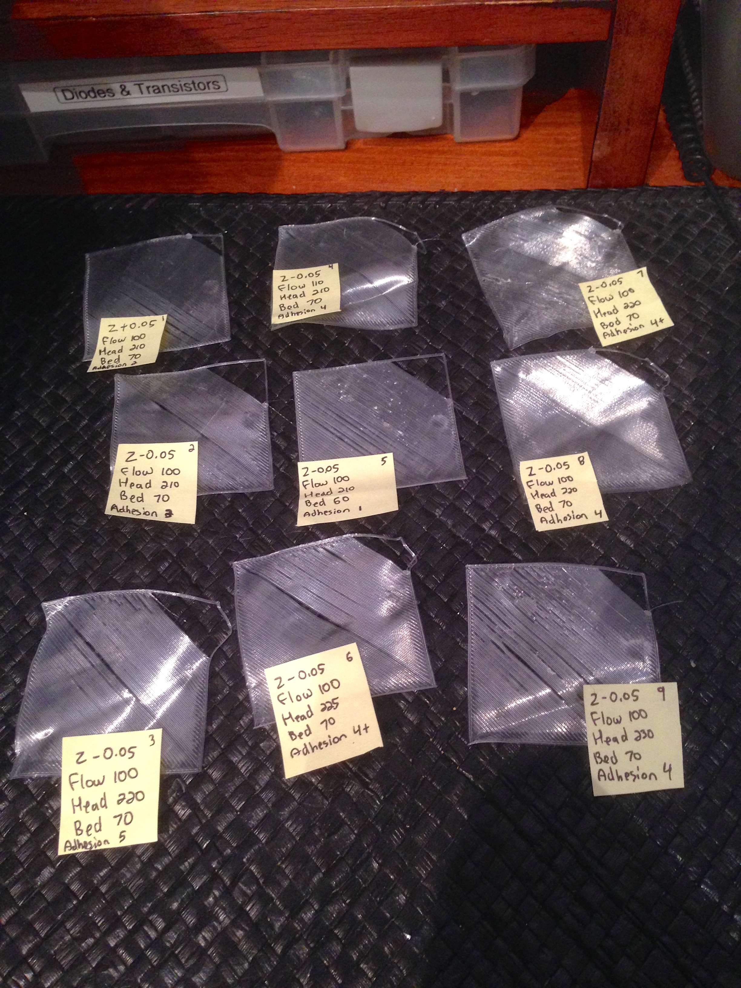
I didn’t fully explore the N-space matrix of combinations for all these options, because I started to see patterns pretty quickly. Quality and adhesion were clearly improved by going up a bit on my head temperature, and starting the first layer a little low (effectively “squishing” it into the bed a bit). The latter is a tip I had read in a few places, and was suggested to me by a Blondihacks reader in an earlier post. Thanks for that!
Now that my first layer was looking great, it was time to print a small test box again.
What I found was that my 220°C head temperature was too high for the later parts of the print, where the plastic needs to bridge gaps and cool quicker to stay in place. I also found that my prints were cemented to the bed so firmly that I had great difficulty removing them without damage when finished. My tuning had worked too well, in a sense.
A little research revealed that a common trick in 3D printing is to use different settings for the first layer or two, then change them as the print head gets higher. Cura comes with a plugin for just this purpose, in fact. I adjusted it so that the head would start at 220°C, and the bed at 70°C, then drop to 210°C and 60°C respectively after the first couple of layers. This worked really well, and resulted in a very high quality test box.
All this tuning has had good results, but has also reminded me that these machines are a hobby, not an appliance. Stuff like this is going to have to get sorted before they become something a person can buy at Walmart, plug in, and start making widgets. They are roughly at the point home computers were in the 1980s- useful, but requiring a level of dedication and knowledge from the user that most people won’t have.
I felt like finally I might be ready to print this ATX box in one go, so I spooled up the black filament (to match the printer, of course), and kicked it off. It was tough to sleep that night, both because of the noise in the other room, and also because I had never really left the machine this substantially unattended before. I checked it before bed, and it was cruising along. I checked at 2am (I’m a restless sleeper) and it was still chugging along. Then I woke up to this…
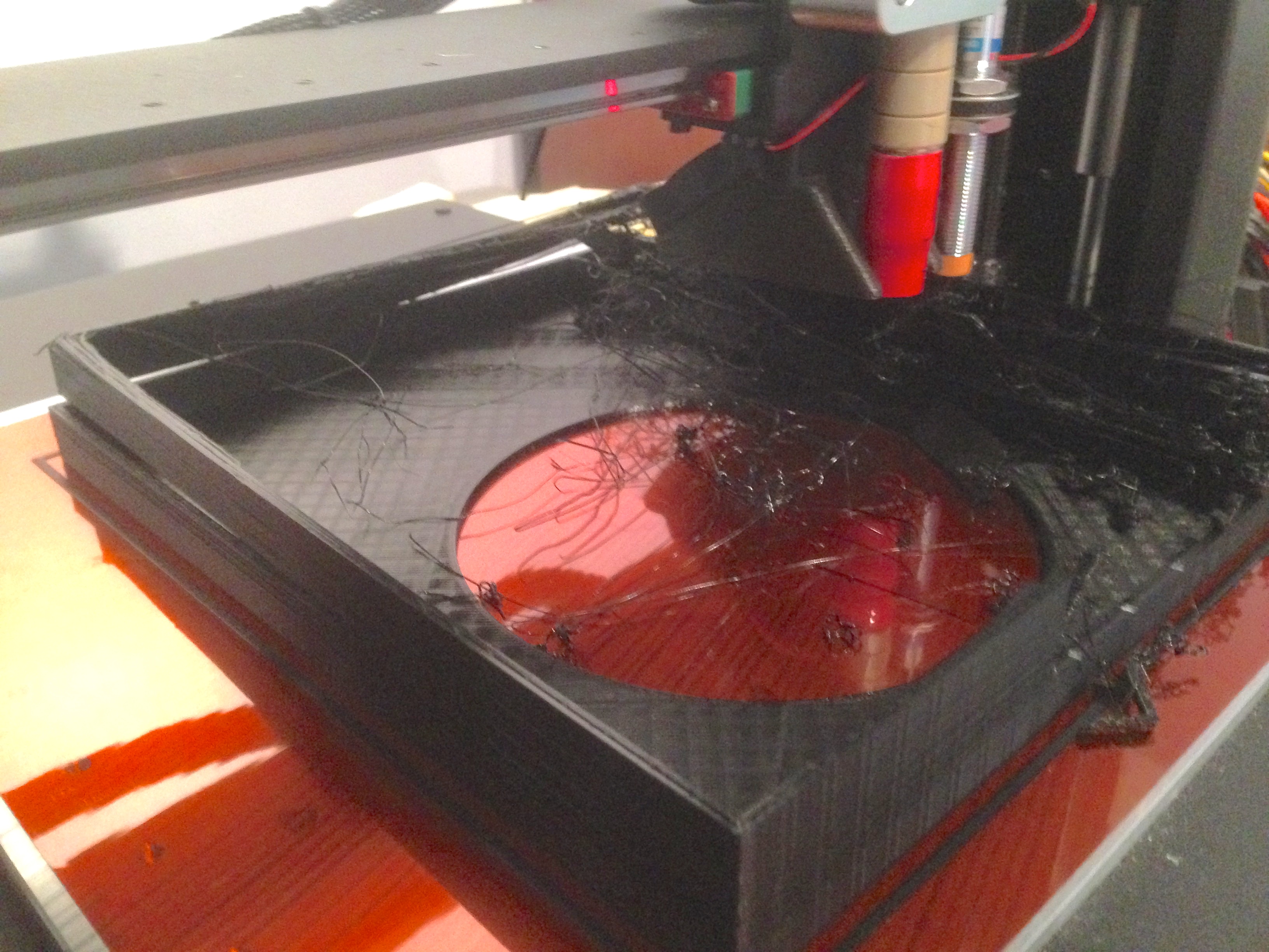
At some point during the night, something went awry, and bedlam resulted. It took some time to clean up the machine after that, I can tell you. From the aftermath, it appears as though a layer half-way up delaminated, causing the upper portion to warp, and impact the head. After that, all bets were off. It’s hard to say what caused this- possibly the colder room at night. I also realized that my bed was about 1mm out of level. Not enough to affect small prints, but as they get taller, this matters more and more. This might have caused an upper layer to get poorly deposited, causing it to separate and warp. Who knows.
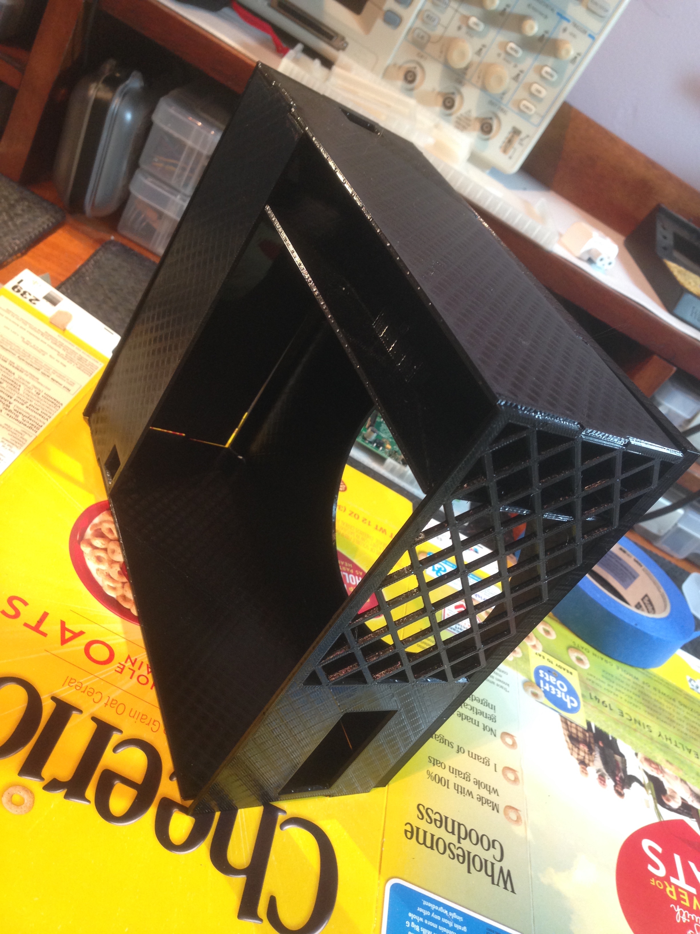
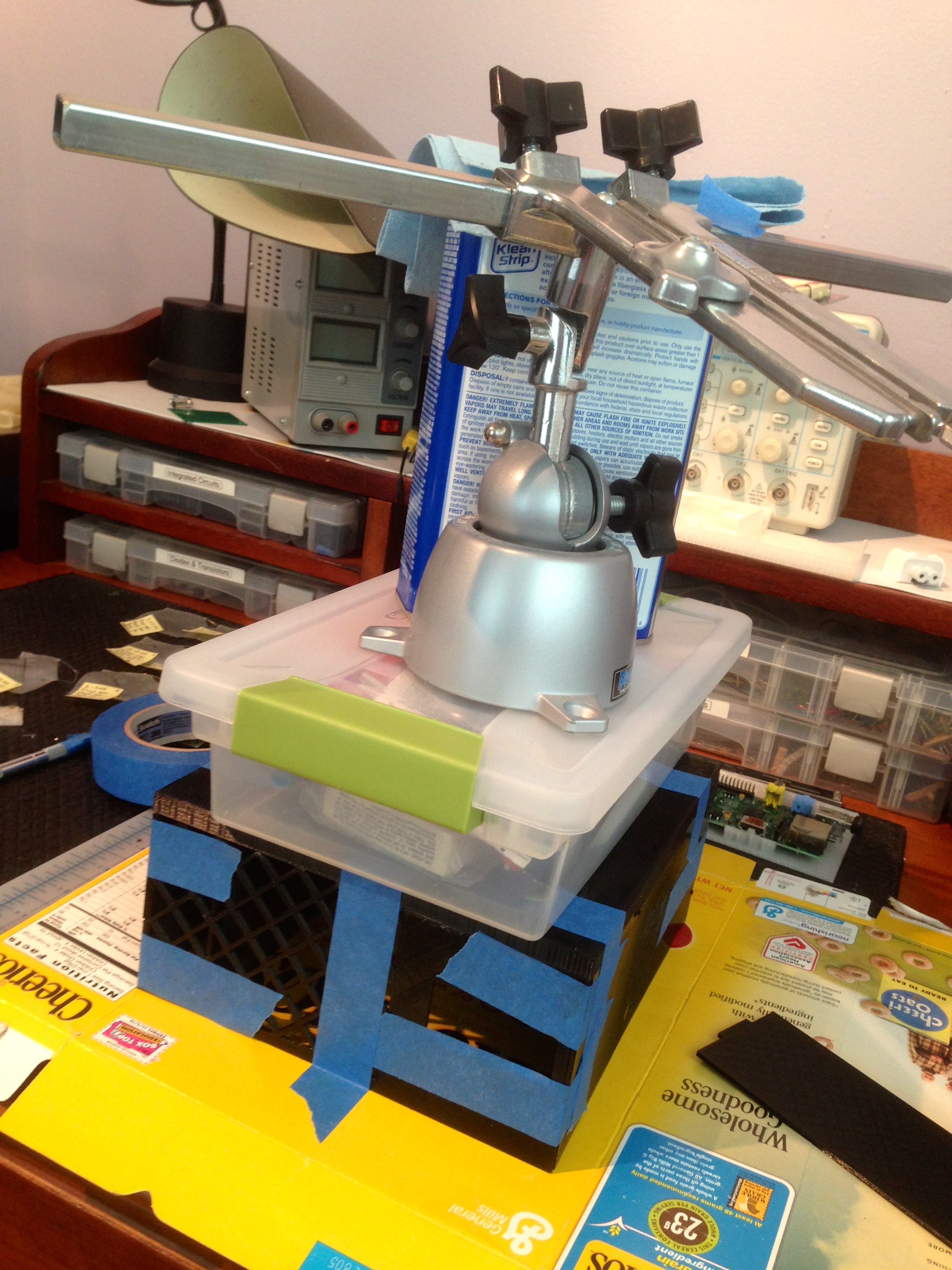
I debated adjusting my bed and trying again, but in the interest of preserving my sanity (and getting some sleep), I opted instead to break the model up into pieces were are easier to print and can be assembled after the fact with cyanoacrylate glue. The other nice thing about breaking it up like this is that I can print the pieces in batches, as I have time, instead of having to commit to a massive two or three day job.
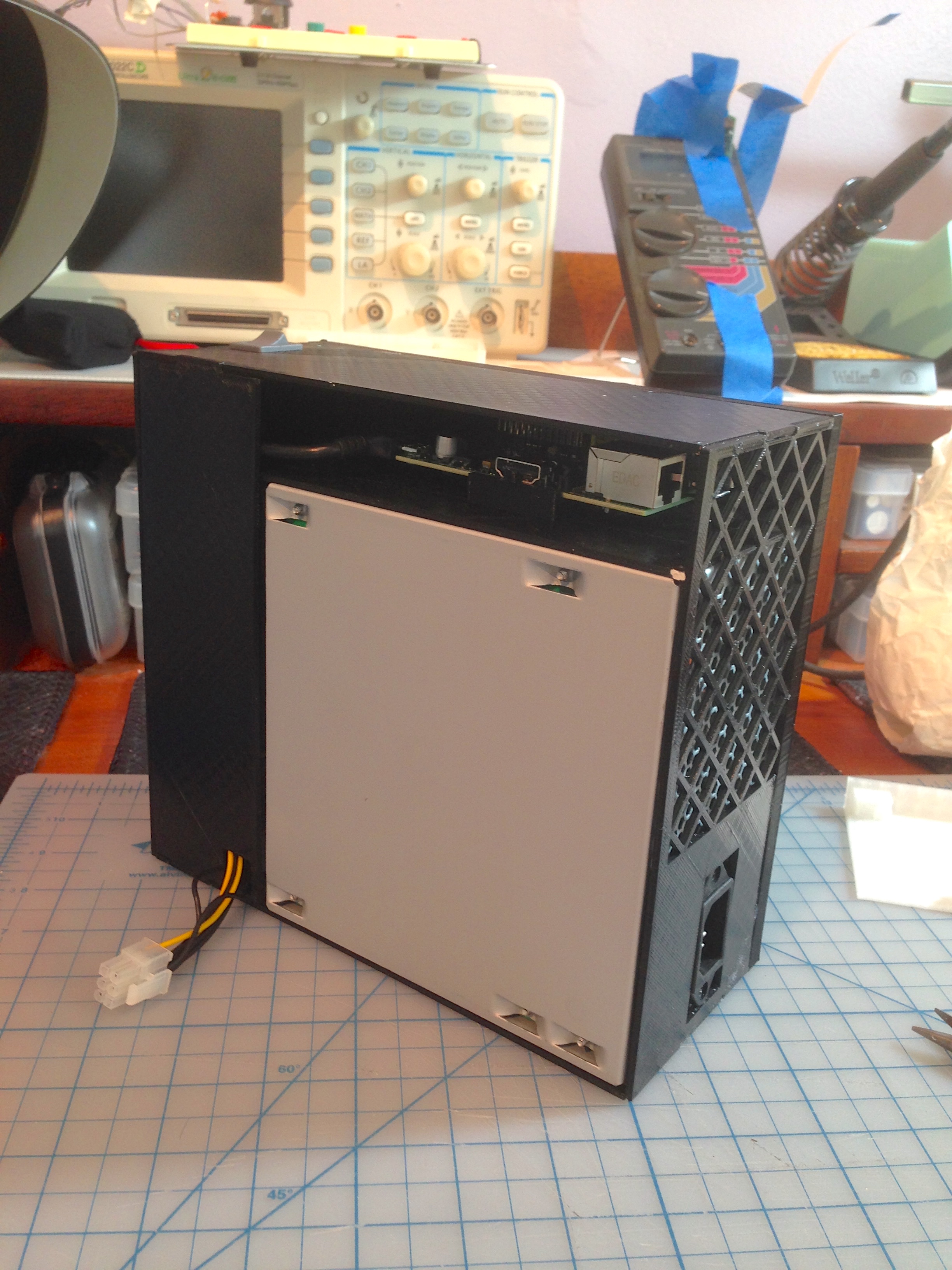
The final power supply/server box turned out pretty nice, if I do say so myself. The only thing I might do differently is that it would be nice for the power outlet to be on the back. However with the way the vents and cabling are arranged on an ATX supply, there wasn’t any way to orient it that also worked with where it needs to sit on the printer. A minor quibble.
Overall, I’m very happy with this heated bed upgrade. It has made the printer so much easier and more pleasant to use that, frankly, I wouldn’t recommend anyone buy a printer without one. It has also enabled larger projects such as this ATX box. My printer is now, I think(?) finally at a point where I can start using it to solve real problems (for certain values of “real”).
UPDATE 4/26/15: I’ve posted all the files for this Print Server project here on Thingiverse. Enjoy!
The .1″ connector on the power supply is most likely (one of?) the floppy drive connector, ‘old’ standards die hard.
I did a double-take when I read: “I was never a build-your-own-PC person”, but I suppose Veronica is more an “artisanal-crafted-PC”.
Heh, yah, I think people know what I mean by “build your own PC”. Assembling graphics cards and CD-Roms and whatever into the best gaming whatever whatever. 🙂
Something to look into is how much current is available on the 5v standby line. It might be enough to power the pi without the supply being turned on. To make it more fun, you can then make the circuit needed to turn on the supply from the pi so that you can go from cold to print without touching it.
It doesn’t seem to be. The Pi dies when I shut the switch off. Honestly, though, I prefer to have it off when not in use anyway.
5VSB is another line on the PSU, separate to the 5V supply line. I forget which colour it is (could be grey maybe? Or purple? Someone correct me here), and can be found on the 20/24 pin motherboard connector; it’s designed solely for powering whatever circuitry is needed to listen for someone pressing the ‘on’ switch, and powering any wake on lan/wake on keyboard/wake on hardware.
There are advantages to both techniques, from what I can see. Having the Pi powered from 5VSB uses much less current than powering it from line voltage, as the rest of the PSU is not alive, and there is also nothing going to the printer. However, at the same time, if it’s not in use, and for how much a 3D printer is generally used anyway (maybe 2 or 3 times per project?), it probably isn’t worth the effort.
Nice work, either way. Would the printer now be able to handle printing the whole thing in one go again, do you think, after tuning it up again like you did? Or would you not trust it enough to try?
Thanks- that’s good information about the ATX. There’s a lot to those things, and they seem pretty useful for a lot of projects.
As for printing it one piece, I have not had the guts to try again. I’m not 100% certain what went wrong last time, so I want to gain more printing experience before trying something that difficult again. I’ve come to realize that an object that basically fills the outside boundaries of the build volume (like a 9^3″ empty box) is the hardest possible thing to print. At the extremes of the build volume is where error is going to tend to accumulate, and the further you get from the bed, the more vulnerable the print is to ambient air currents and such. If I try this print again, I’ll do a very OCD bed leveling, and rig up and enclosure of some sort. However, the prospect of running the machine 24-36 hours straight and wondering the whole time if something has gone horribly wrong is making me wary of trying again. I’ll soon have my live video feed of the machine set up through Octoprint and the Pi Camera, which will help a lot, because I can keep an eye on it, and cancel the print remotely if things go pear-shaped (possibly literally).
A box just slightly bigger than the printer lined with something like fiberglass insulation might also help with the noise.
Just a couple of observations to add to the flood of comments I presume you will get when writing about 3D printing:
1) The makerware software I use has the option to print with rafts- before starting the print it lays down a layer of mesh (like a fly swatter, or a sieve) that forms a base for the actual print. It has a large footprint for good adhesion to avoid warping, but it’s easier to remove from the bed than a solid flat layer. It seems to help with large prints, you might find it worth experimenting with.
2) The replicator 2X I use has an enclosed build volume, which means the print is held in a warm atmosphere. This also seems to help prevent large prints from warping and helps inter-layer adhesion on big prints when the top cools down before the next layer is deposited. You might want to try running your printer inside something like a storage box or a fish tank- it would keep the air warm and reduce noise to help you sleep 🙂
Cura has raft, skirt, and brim options, but I haven’t played with them much. The “mesh brim” you describe sounds interesting. I have found I can create that by raising the model a tiny bit off the bed in Cura, and setting the support type to Grid. Cura then builds a support to fill the void under the model.
My research concurs with what you said- upper layers delaminating is likely due to temperature control issues in the air around the machine. Next time I try a print that big, I’ll shield the build area with cardboard or something.
The odd usb cable looks like its a USB OTG cable, there are some devices (phones mostly I think) that can act as both host and slave. It means you can use normal USB devices on a device that only has a microUSB connector.
Whatever it was, it’s dead now. 🙂
For the record, a kapton bed surface has a very good adhesion to ABS plastic, but not so much with PLA.
The fact you have a heated bed helps the PLA not warping, but you’d have a similar result on a sheet of glass.
If you ever want to print ABS you will have to change how much you “squish” the first layer when you change plastic : if you push the ABS on the kapton as much as you do to the PLA you will ruin your tape when you remove your part.
Yah, I learned that after installing my heated bed. Some people suggest putting blue tape over the kapton for PLA, but I honestly had lousy luck with the blue-tape-and-glue method. I found a way to dial in the kapton for PLA, so I’m happy. Thanks for the tips on ABS- I’d like to try that son.
Yeah, if it works for you, do not fix it 🙂
That white connector will probably be a JST connector, you can buy the sockets/plug housings and solderless terminals discretely and can build up any configuration of cable you need.
I use them all the time on PCBs, they are much more compact and neater than soldering wires to male and female headers, and because you can use a keyed socket you eliminate the chance of accidentally reversing a connection (like PrintrBot have done). Pitch is deliberately the same as headers so they are compatible.
I get mine from RS, they’re very cheap.
Yah, it’s a pretty standard keyed header connector, of the sort used in pinball machines, computers, etc. I didn’t happen to have a mating connector on hand though, and I loathe waiting for things to ship.
The title of this article surprised me a bit; I’m wearing the shirt right now. An awesome post, as always.
Do you have a place where I can download the files for your ATX/RPi case? I’ve got a Printrbot Simple Metal with a heated bed and a Raspberry Pi 1 Model B, and this is just what I need! Epic job!
Thanks for reminding me- I intended to put all the files on Thingiverse, and forgot. Here you go:
http://www.thingiverse.com/thing:794525
The description explains what all the files are- there’s two versions of it.