Wrapping up the prototype for retrogaming on the go.
A while back I started working on a gamepad for Apple II-series computers. It’s now time to make it an actual thing!
This is the perfect project for which to bust out the new 3D Printer. See how I justify its existence in my lab? It’s so useful.
I said IT’S SO USEFUL.
Ahem.
Now then, as with any 3D printing project, step one is getting a 3D model of what you want to build. I knew I wanted to used my Parallax joystick, but getting the mounting points and rotation ball opening lined up just right can be quite tricky. I thought I could save myself some effort by modifying an existing model that is close to what I need. I dug up this cool project on Thingiverse:
It’s a homebrew portable game console, based on an Adafruit project. Super cool! It’s one of the nicest homebrew 3D models I’ve seen, and it’s conveniently broken out into modular sections. They have also done the hard work of lining up the openings for a thumbstick, and it has very nice joinery between the sections. I took the end pieces and mashed them together in 123D Design:
Never satisfied with doing one new thing at a time, I also took this opportunity to try 3D printing with ABS. Generally, you start out with PLA, which is a vegetable-based plastic with a hard surface. It’s easy to print with, so it’s a logical choice. However, ABS plastic has a lot of advantages. It has a nicer feel to the touch (it’s “softer”), and the resulting objects look and feel more like commercial products. It also has the big advantage that there is an easy solvent for it- acetone. Solvents for PLA tend to be of the “you don’t want them in your house” variety. A couple of options include Chloroform and Dicholormethane, but neither of those are particularly pleasant to use or easy to acquire. Acetone has some effect on PLA, but it’s not a proper solvent. Acetone will completely dissolve ABS, which is very useful indeed.
There are a few reasons a proper solvent is desirable:
1) You can permanently bond pieces together (they melt together and become one- far better than any glue)
2) You can smooth printed surfaces easily. This improves appearance and strengthens the piece greatly.
3) You can create a slurry to apply to the print bed for better adhesion (which prevents warping and other problems).
Acetone can be bought by the gallon at any hardware or paint store, so it’s very convenient indeed. The tradeoff for all this is that ABS is more difficult to print with. As you’ll see later, I have a fair bit to learn in this area.
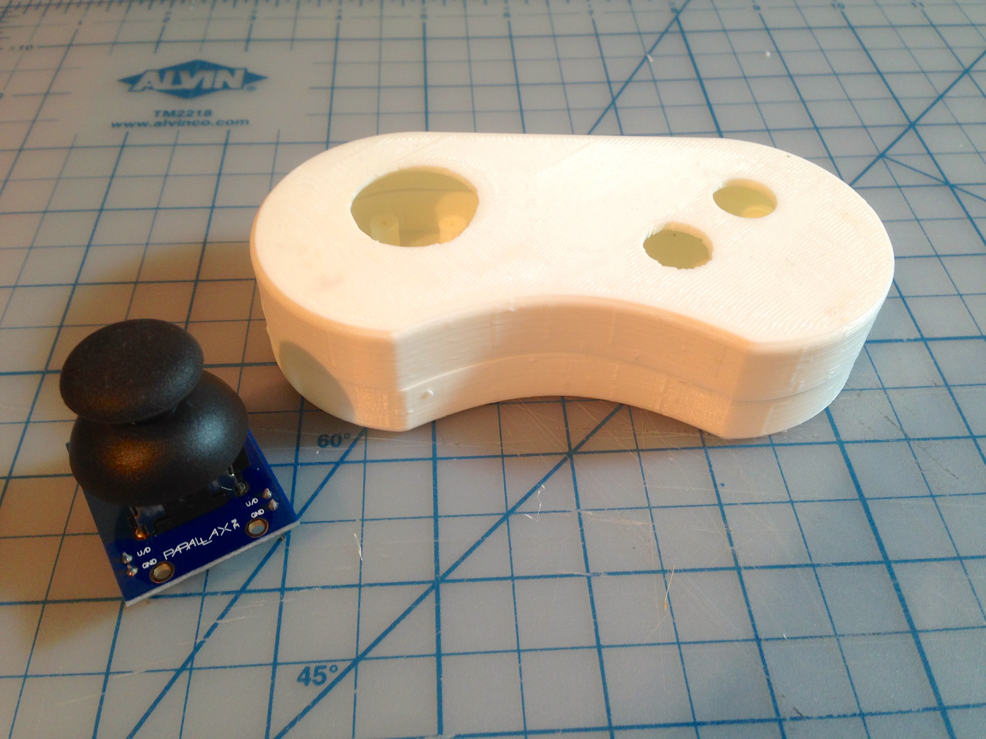
Anyway, back to our model. This mashed-up gamepad model printed quite nicely in white ABS, as you can see here.
Unfortunately…. it didn’t fit. In a classic Blondihacks facepalm moment, I neglected to actually measure the mounting points and openings for the joystick. They looked about right at a glance, and I just assumed these sticks were some kind of standard, I guess. You see where this is going, of course. The Parallax joystick I happen to have wasn’t even close. The mounting points and opening are all incorrect and there was no making things fit.
Honestly, this is just as well. I wasn’t crazy about the overall shape and size of the Frankenpad I had created from that other person’s lovely model. Time to bite the bullet and dust off my own 3D modeling skills. I should have done this from the get-go. Software like 123D Design is so pleasant and quick to use that I was able to model my own gamepad, perfectly suited to my needs, in a couple of hours.
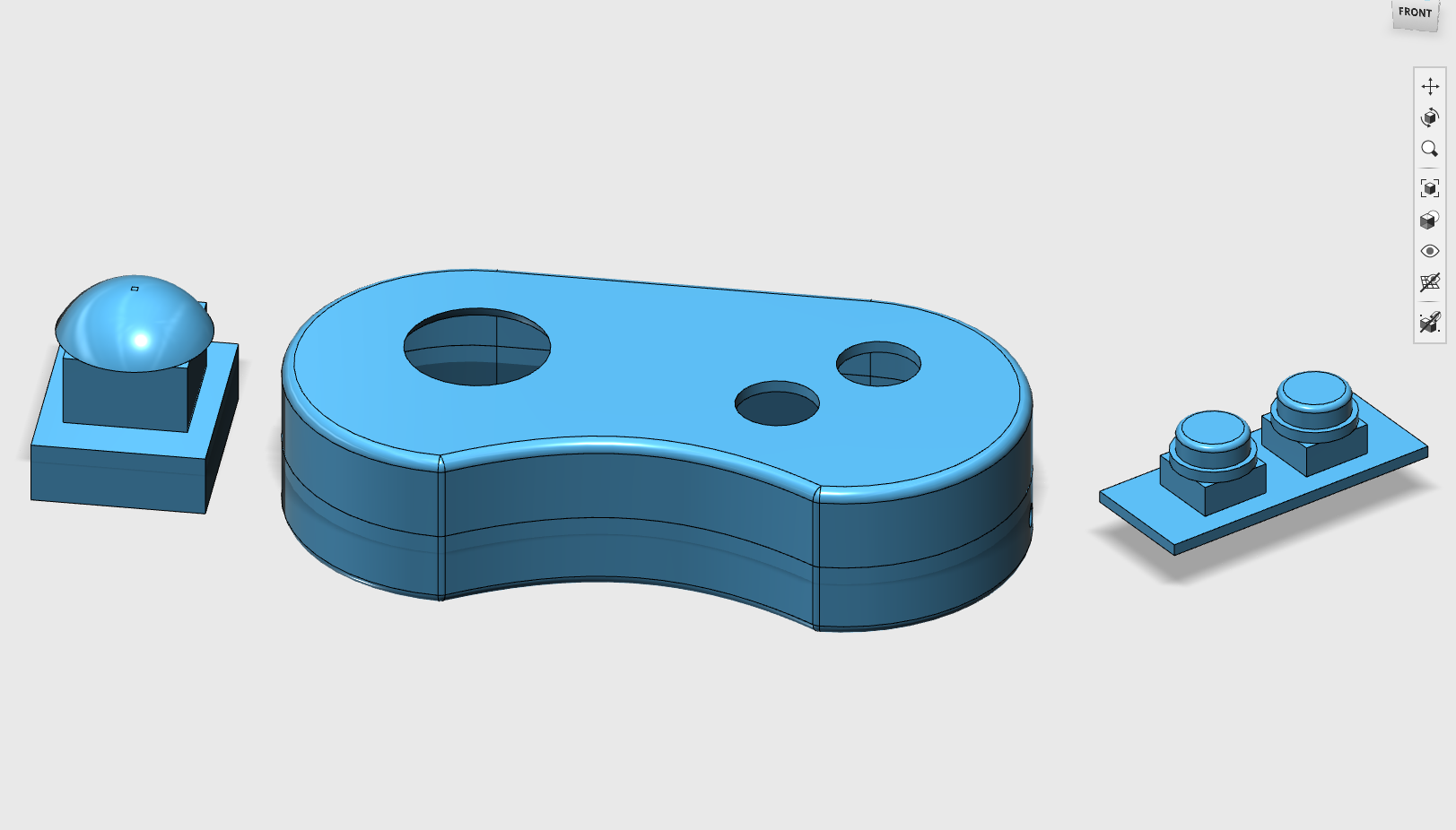
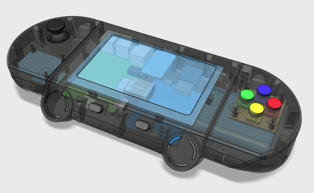
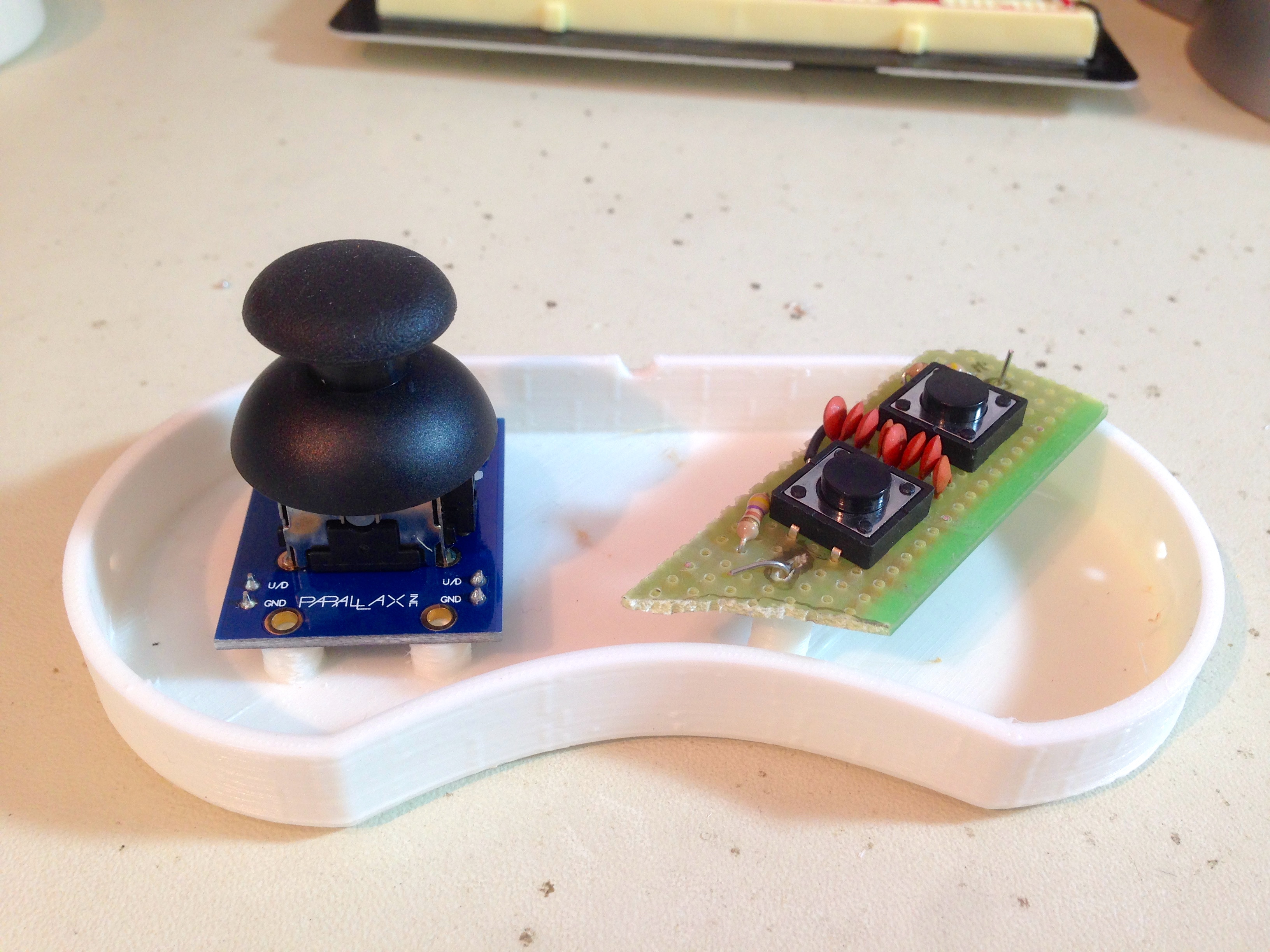
My concerns about getting things lined up right with the buttons and joystick were largely unfounded. Really, all I needed to do was take measurements off the pieces I had, make models in 123D Design, then design the gamepad around them. In the image above, you can see where I modeled the essential dimensions of the joystick and buttons (including tactile switches and mounting PCB). In fact, once you’ve done this, you can use simple boolean operations to make clearances and access holes for things. For overall shape and dimensions, I loosely modeled this on the Super Nintendo controller, although it needed to be a bit thicker to accommodate the analog stick. I’m still new to consumer product engineering, so there’s lots to learn. If anyone who does this for a living is reading this, no doubt you are rolling your eyes at the rookie mistakes I continue to make.
Time to print! Well, actually, time for a whole new class of mistakes. Now that I’m trying my hand at ABS, we have a few new lessons to learn about 3D printing.
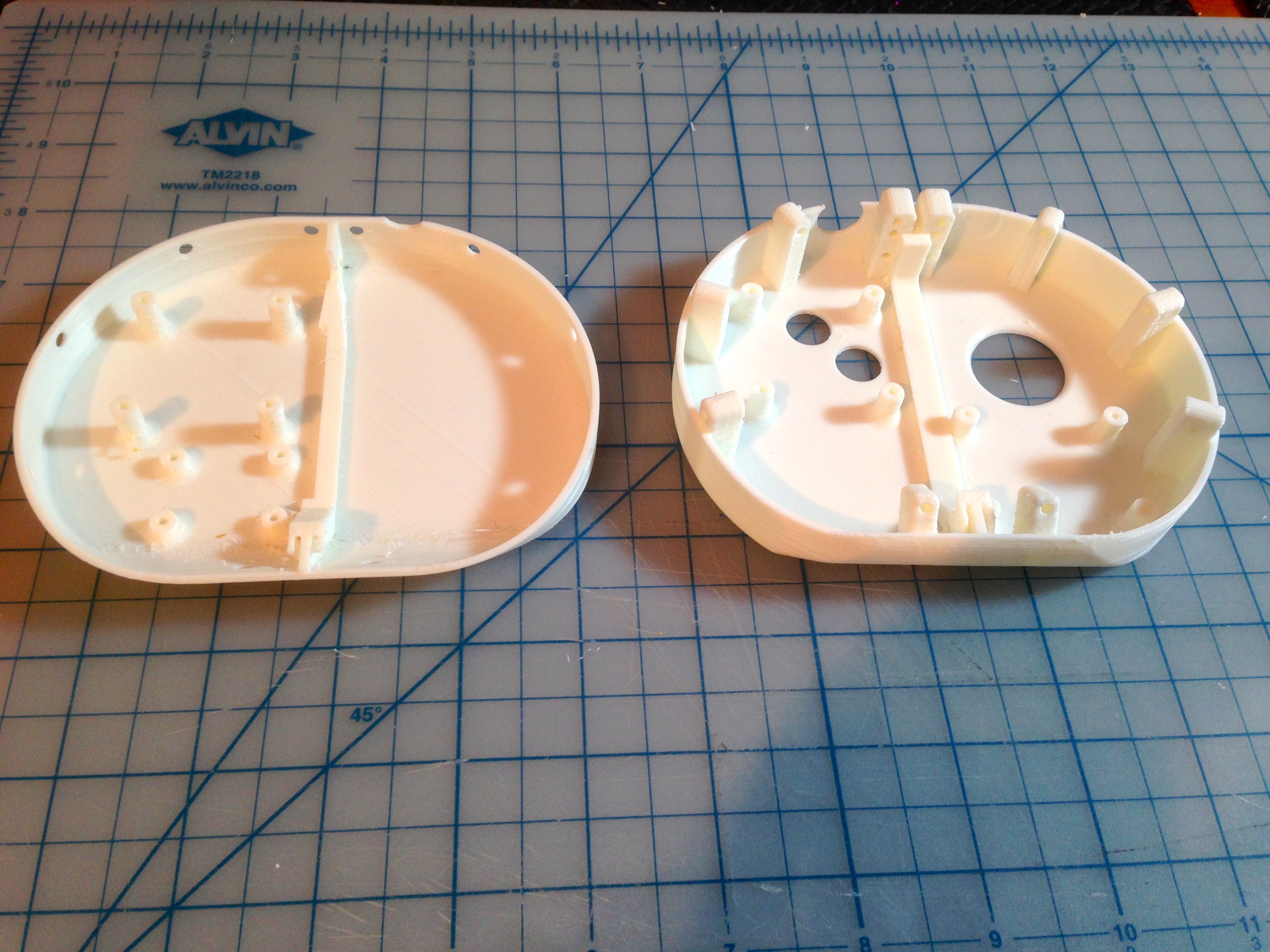
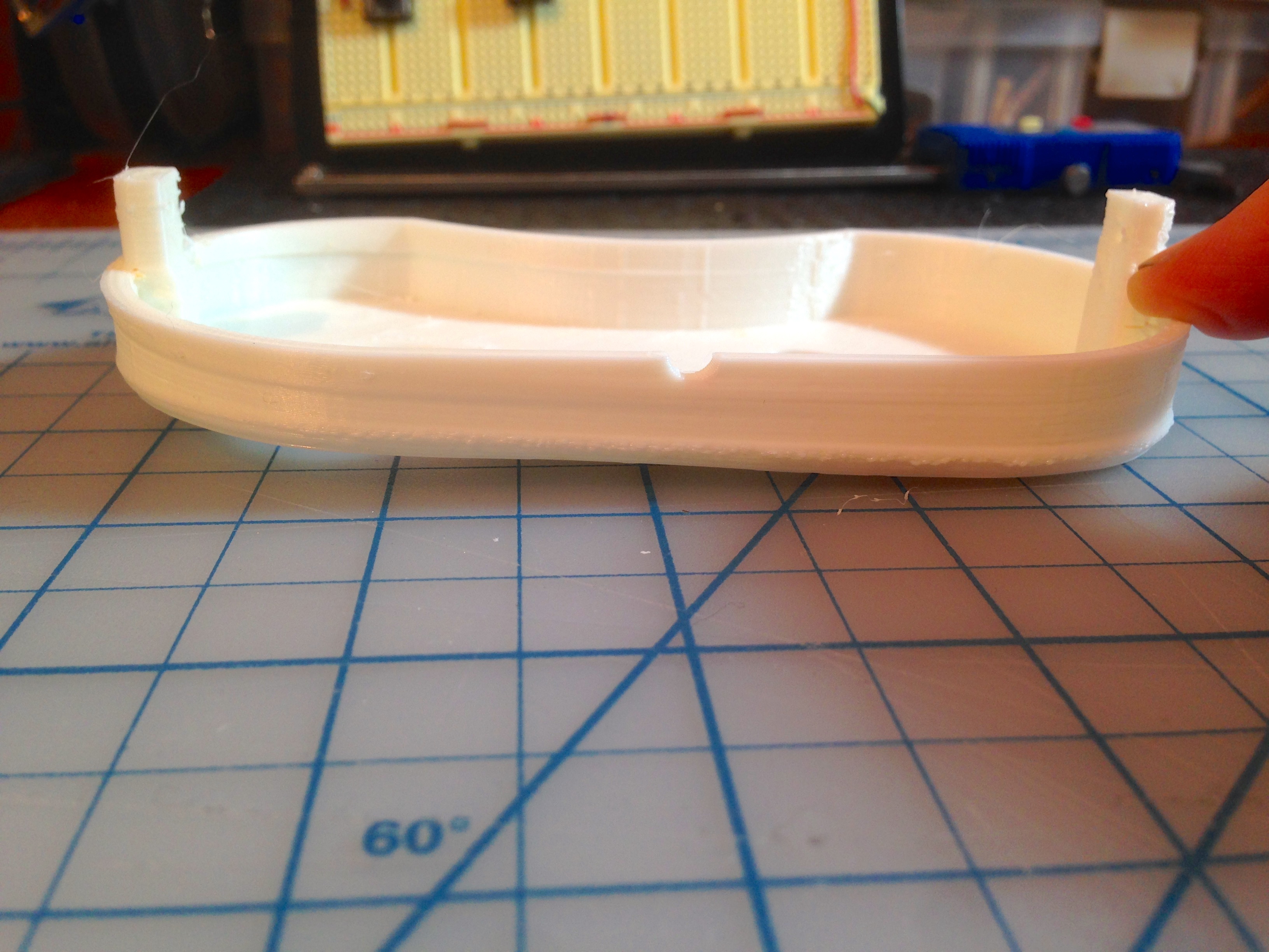
That first attempt might seem swell, but if you look closely, you’ll see I did some hand carving of all the openings. Things didn’t quite fit, because ABS shrinks more than PLA does when printing. All of my openings were too small. Lesson learned! There’s another problem, which you can’t see in this photo. The top half of the case has a big crack all the way down the side. I’m pretty paranoid about bed adhesion when printing, and I had heard ABS is particularly tough here. To compensate, I had the heated bed cranked up about as high as it would go (90°C), and used an ABS slurry on the bed. The latter is a technique were you mix up a solution of acetone and scraps of ABS (about the consistency of skim milk), then spread it on the bed. This is really, really effective. In fact, it is so effective that I couldn’t remove the piece from the bed without destroying it!
After getting burnt (figuratively and literally) with the superheated-bed-and-slurry approach, I dialed everything back a bit and reprinted the top half.
Yep, the second attempt warped quite badly because the bed adhesion was insufficient to overcome the natural tendency for differential cooling in 3D printed models. Clearly I needed something between “hot clean bed” and “crazy hot slurried bed”. For my next attempt, I cranked up the bed heat again, but still no slurry.
Note to self: Crazy Hot Slurried Bed is my next band name.
Running out of options now, I’ve gone back to the slurry method, and focused instead on finding a better technique for removing things from the bed. The trick is that you don’t want to damage the Kapton tape or the soft aluminum of the bed. That rules out things like pry bars, razor blades, and most metal tools. PLA models are also sometimes over-enthusiastic about remaining on the bed, but I have had good luck using large channel-lock pliers to twist them off (using a rag to protect the model from the jaws of the pliers). For ABS, that wasn’t working. These things were really stuck. I tried credit cards, plastic scrapers, a rubber mallet, and also swearing a lot. No amount of swearing seemed to help- I have plenty of data on that.
In the end, what worked really well was a weird tool (one weird trick?) that I found in the back of my toolbox.
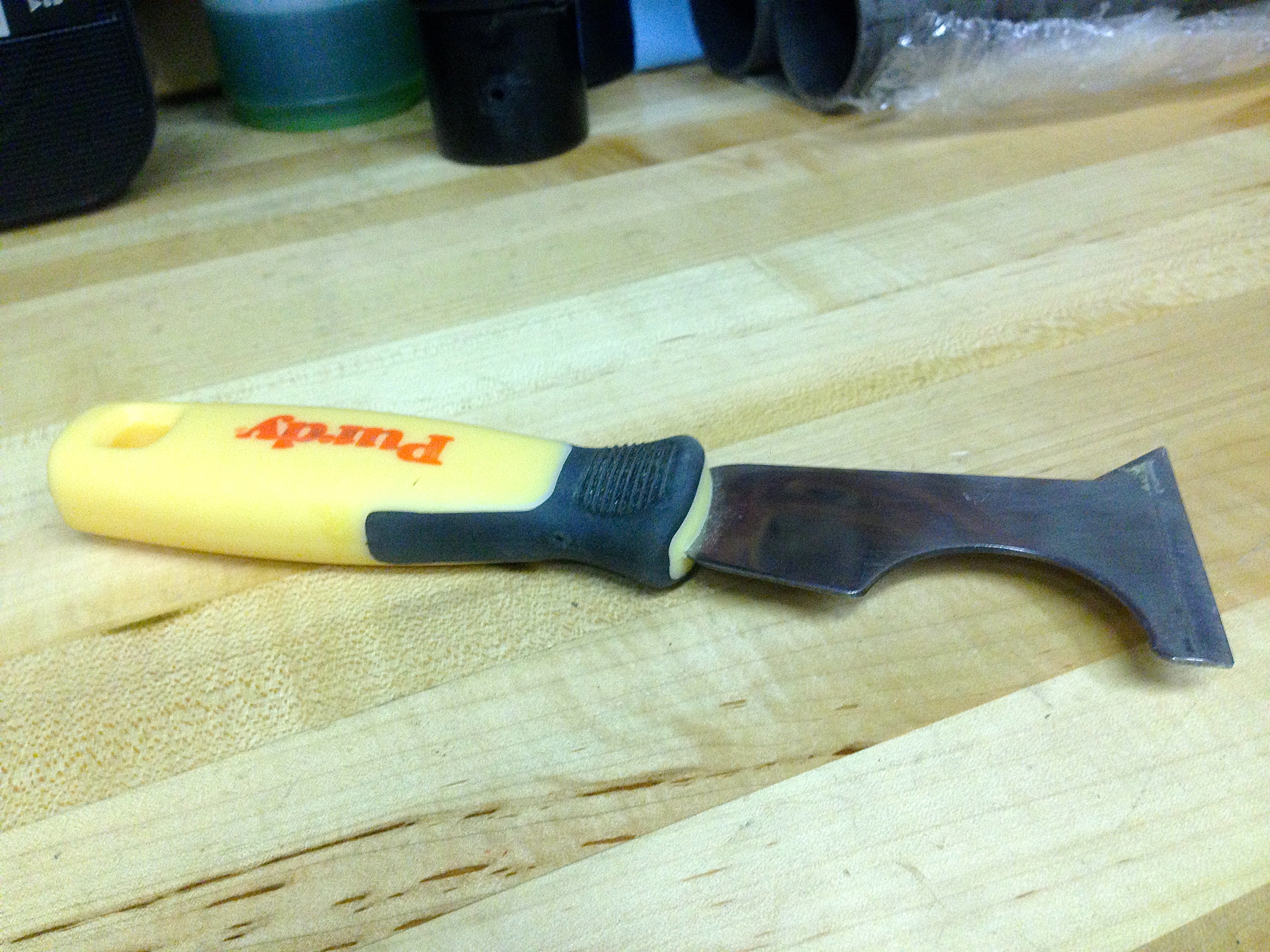
This tool is metal, which I wouldn’t normally condone applying to your print bed in anger. However it’s not actually very sharp, and seems to have just the right angle on the end for popping things off the bed. It’s like dull paint scraper, or a very dull chisel, you could say. Whatever this thing is, I’m sure it was acquired at Home Depot (if you want one).
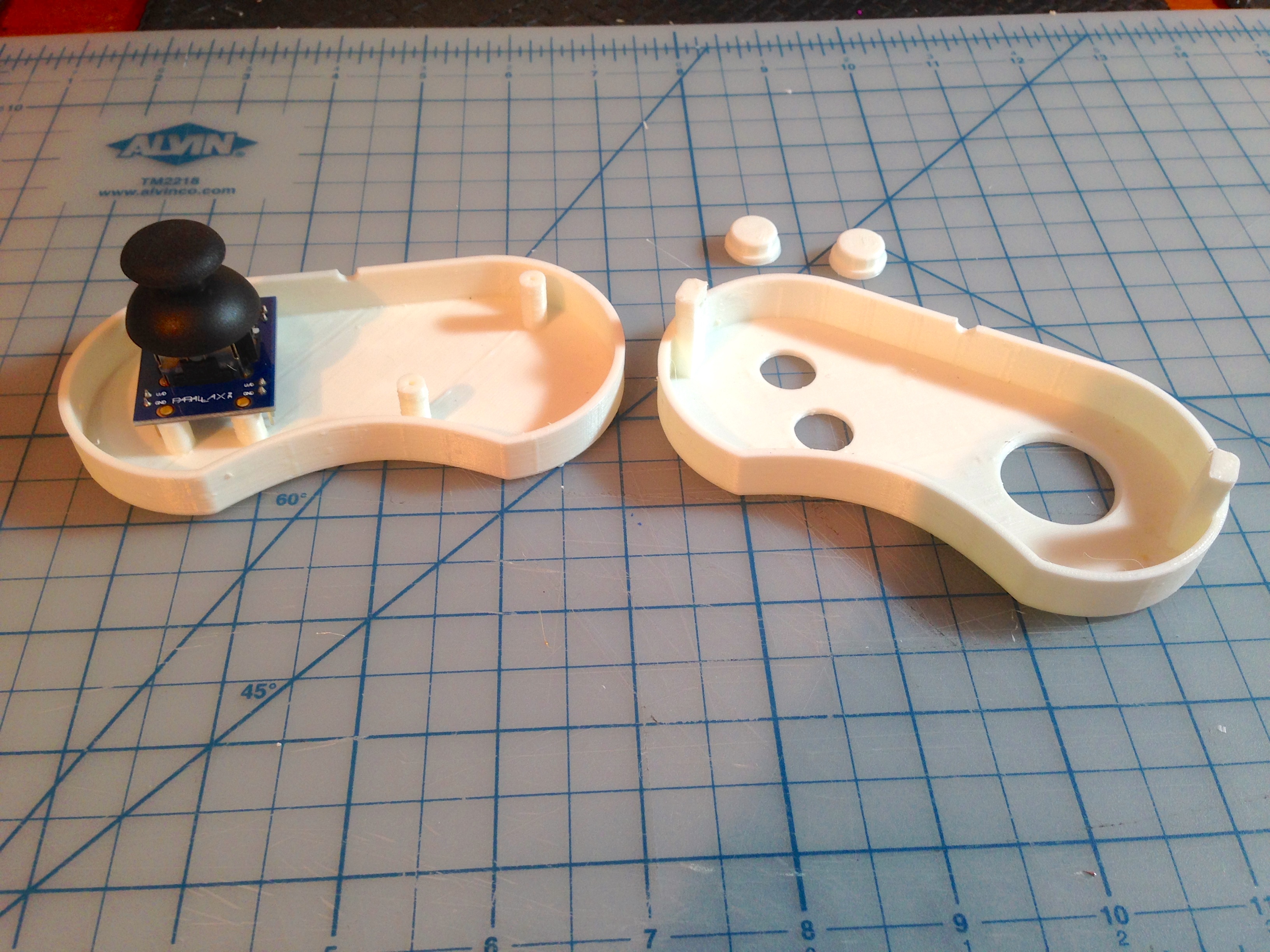
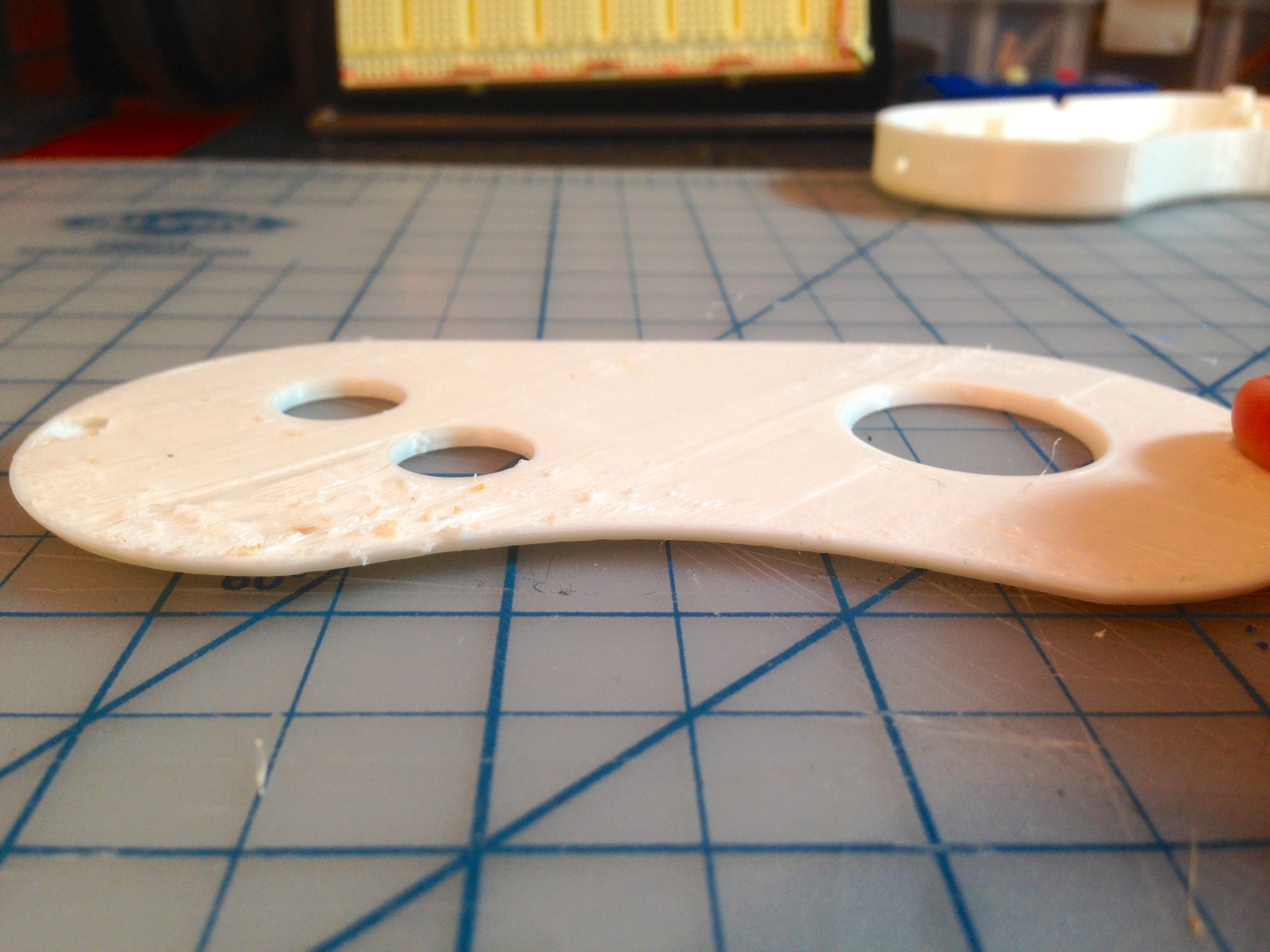
The opening for the joystick turned out to be a bit more of a challenge. Enlarging it would work, but would expose too much of the ball, meaning you can catch your fingers when the stick is moved all the way in one direction. The opening needed to be about 4mm higher up. That would have required printing all new pieces, and would have made the gamepad 4mm thicker. Instead, I opted to lower the stick by 4mm. Since the Parallax stick is designed to go in a breadboard, it has long header pins on the bottom. I can easily cut those off and lower my mounting posts to get that 4mm back.
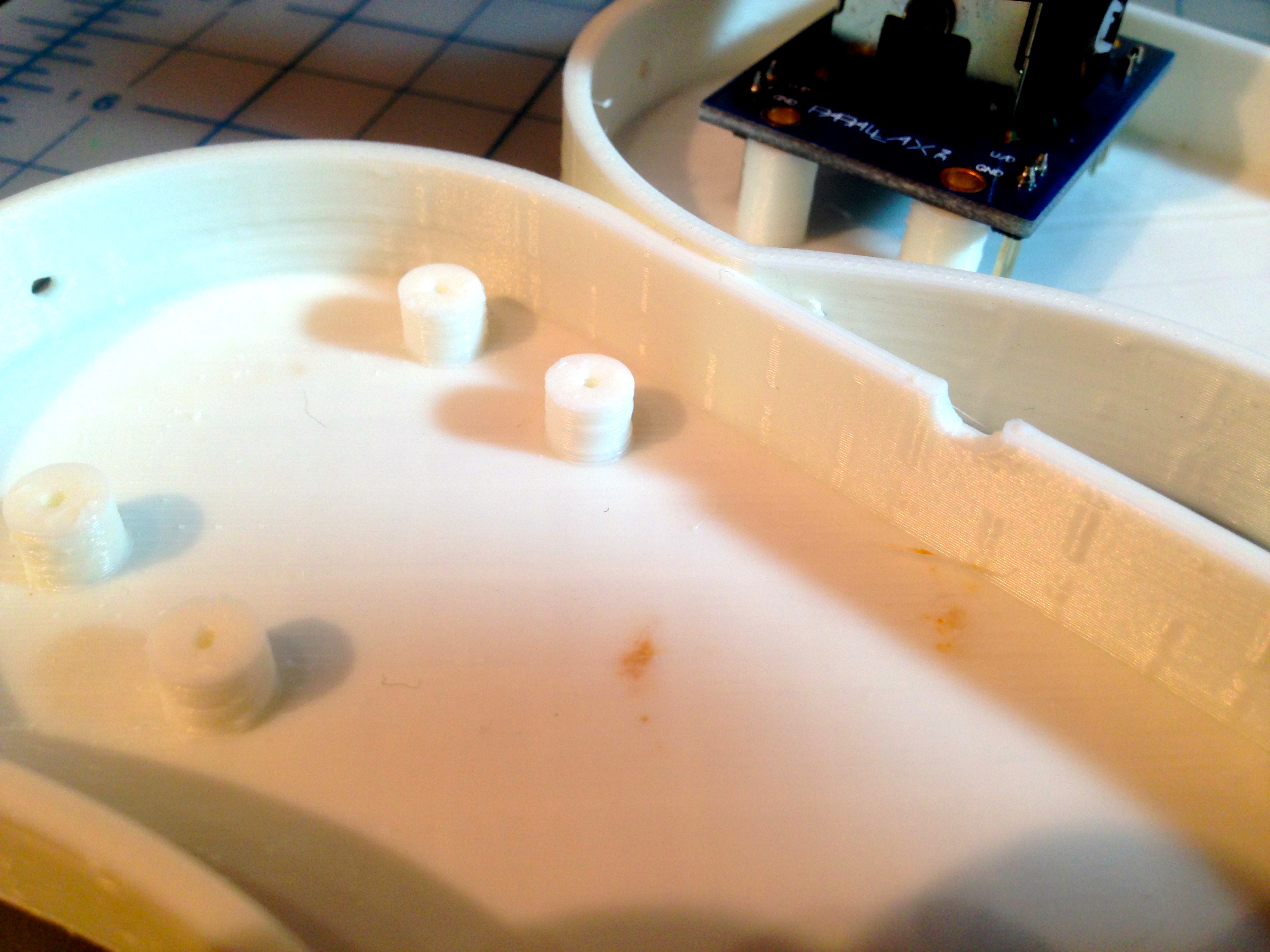
You can see in these close-ups that my print quality with ABS is good, but not great. I’m still getting things dialed in and figuring out the tricks. PLA is definitely easier!

With the shell sorted, it’s time to get the electronics moved off the breadboard and into their proper home.
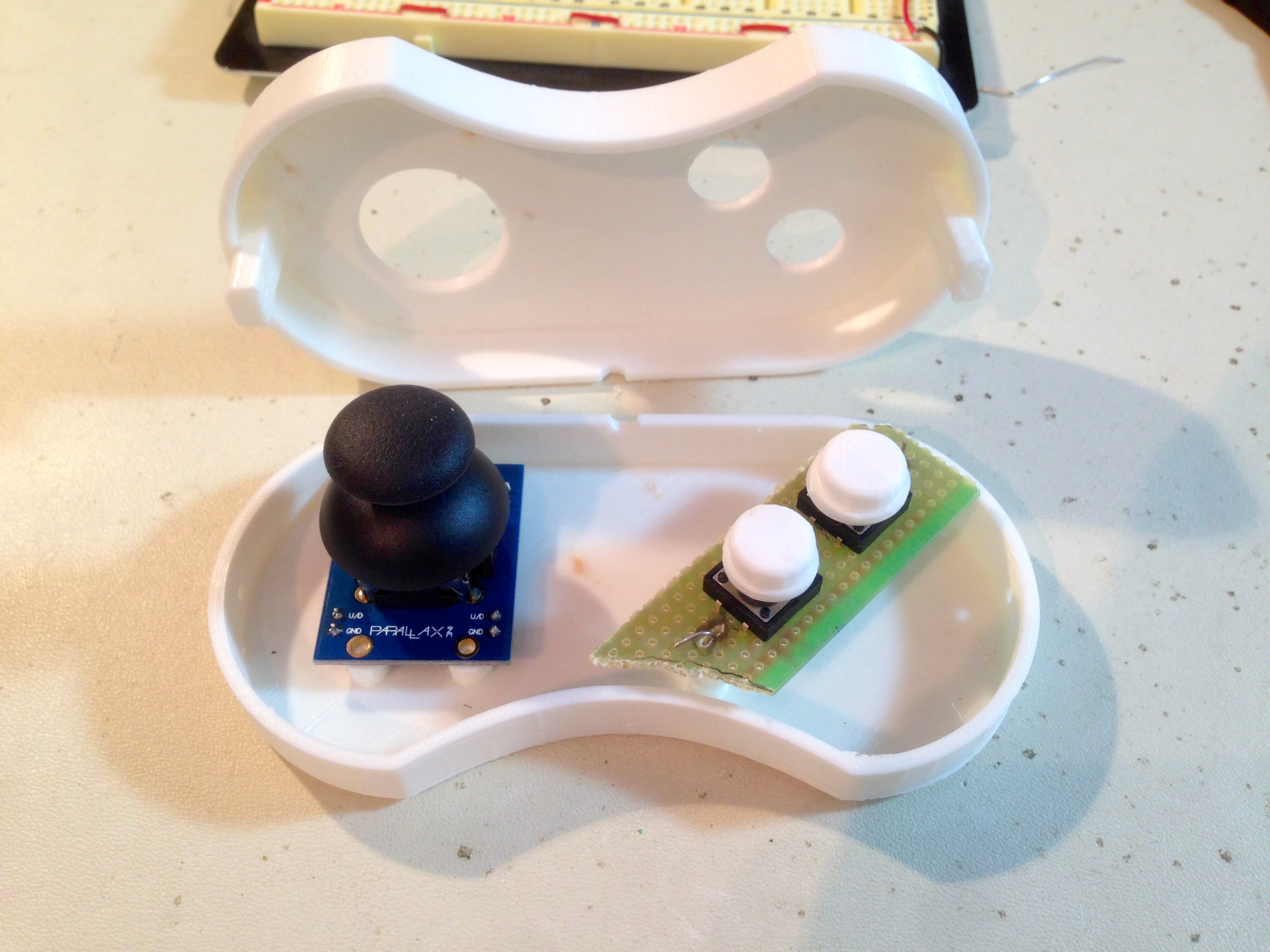
This circuit is so small and simple that I’m stepping out of character and not etching a PCB. I’m using Jameco’s prototyping board, which has square pads placed very close together. That makes it easy to use solder bridges to form simple circuits. The result is not very pretty, but it’s quick, robust, and effective.
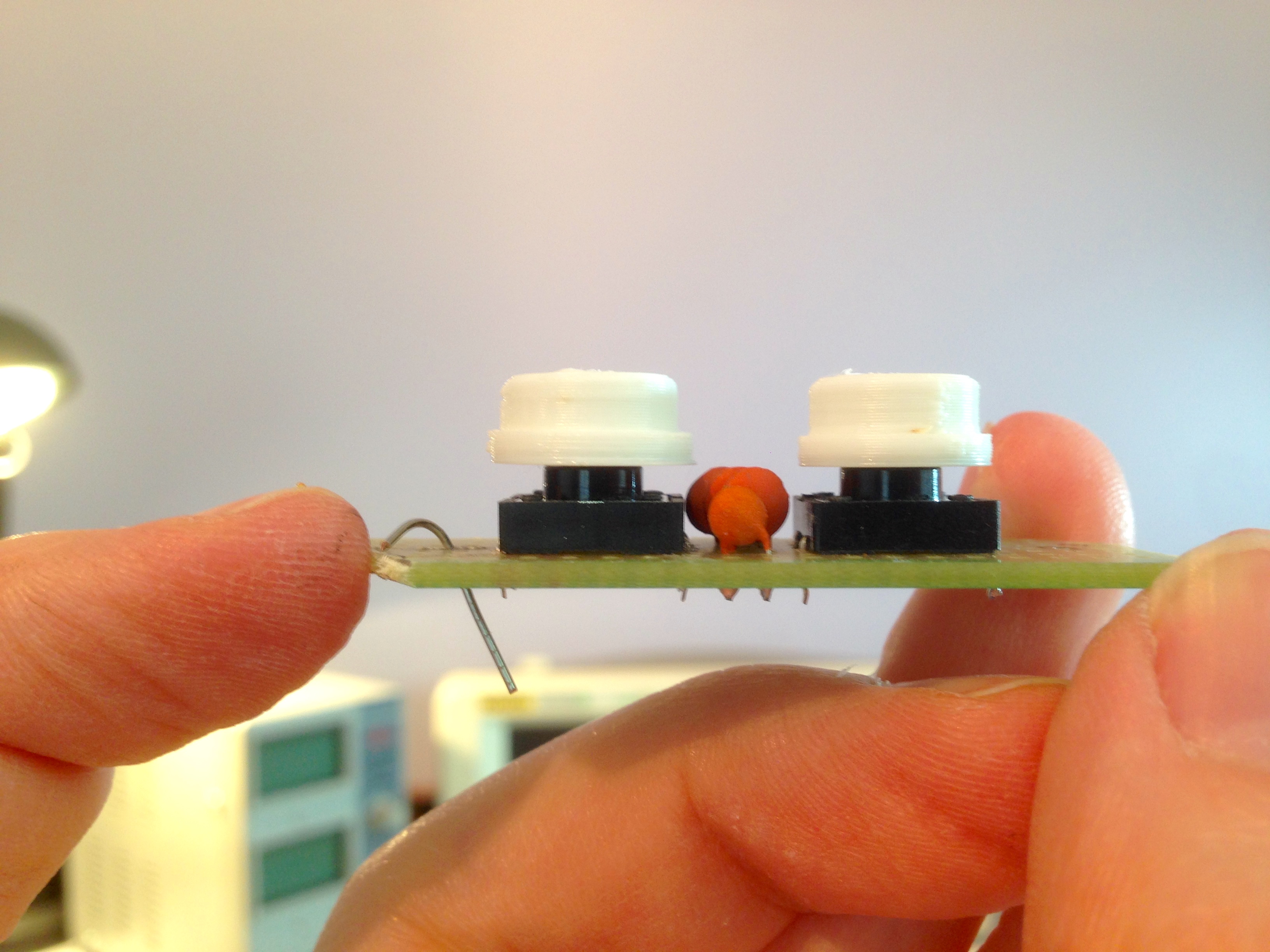
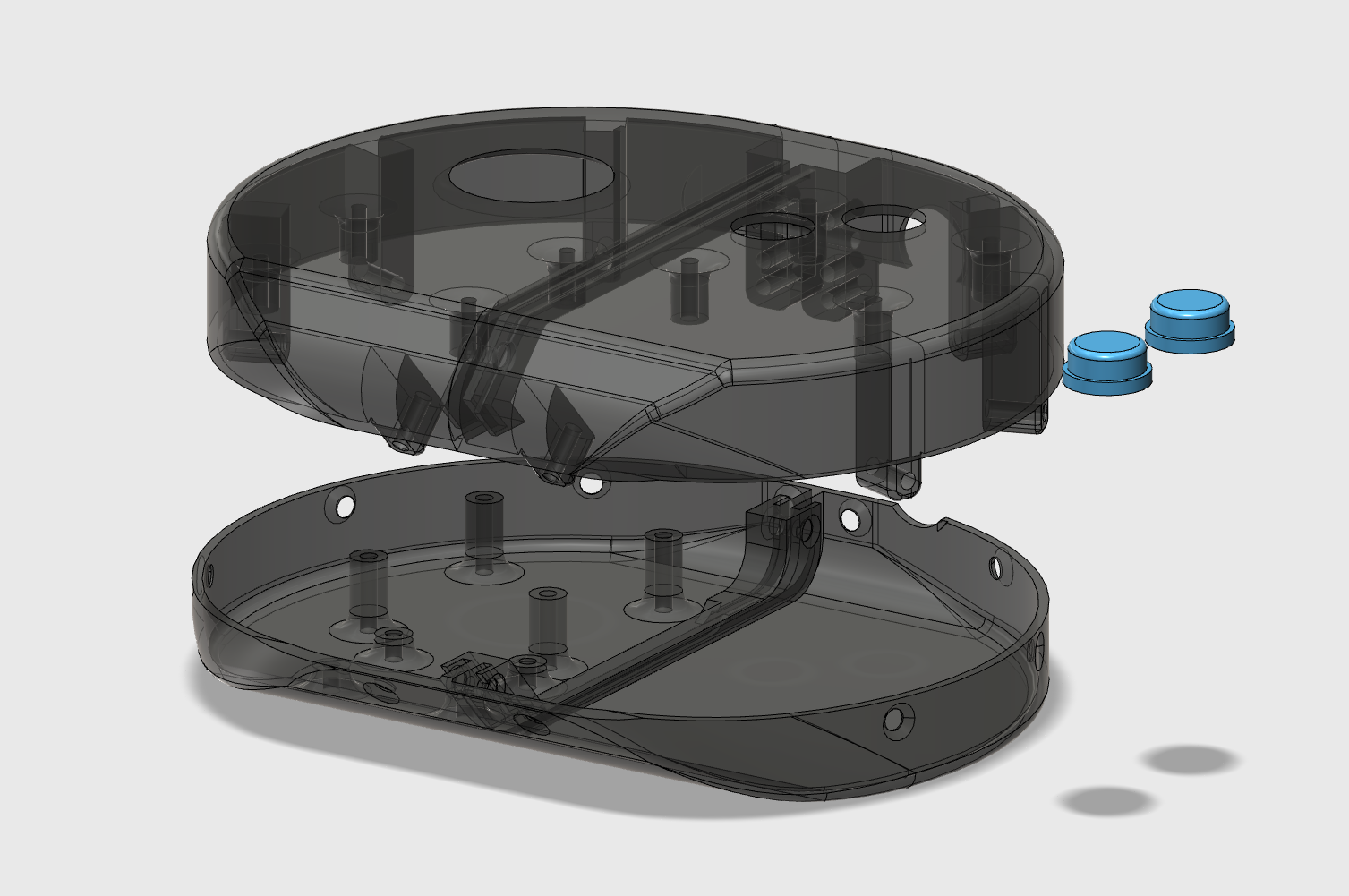
Note the design details of this device; using mounting posts in the lower shell, floating the buttons on top of tac-switches held in by their openings, etc. These methods are borrowed from commercial consumer electronics. Whenever you take something apart, take note of how the components work together and how the enclosure is designed for easy manufacturability. These techniques are very powerful in the world of home 3D printing.
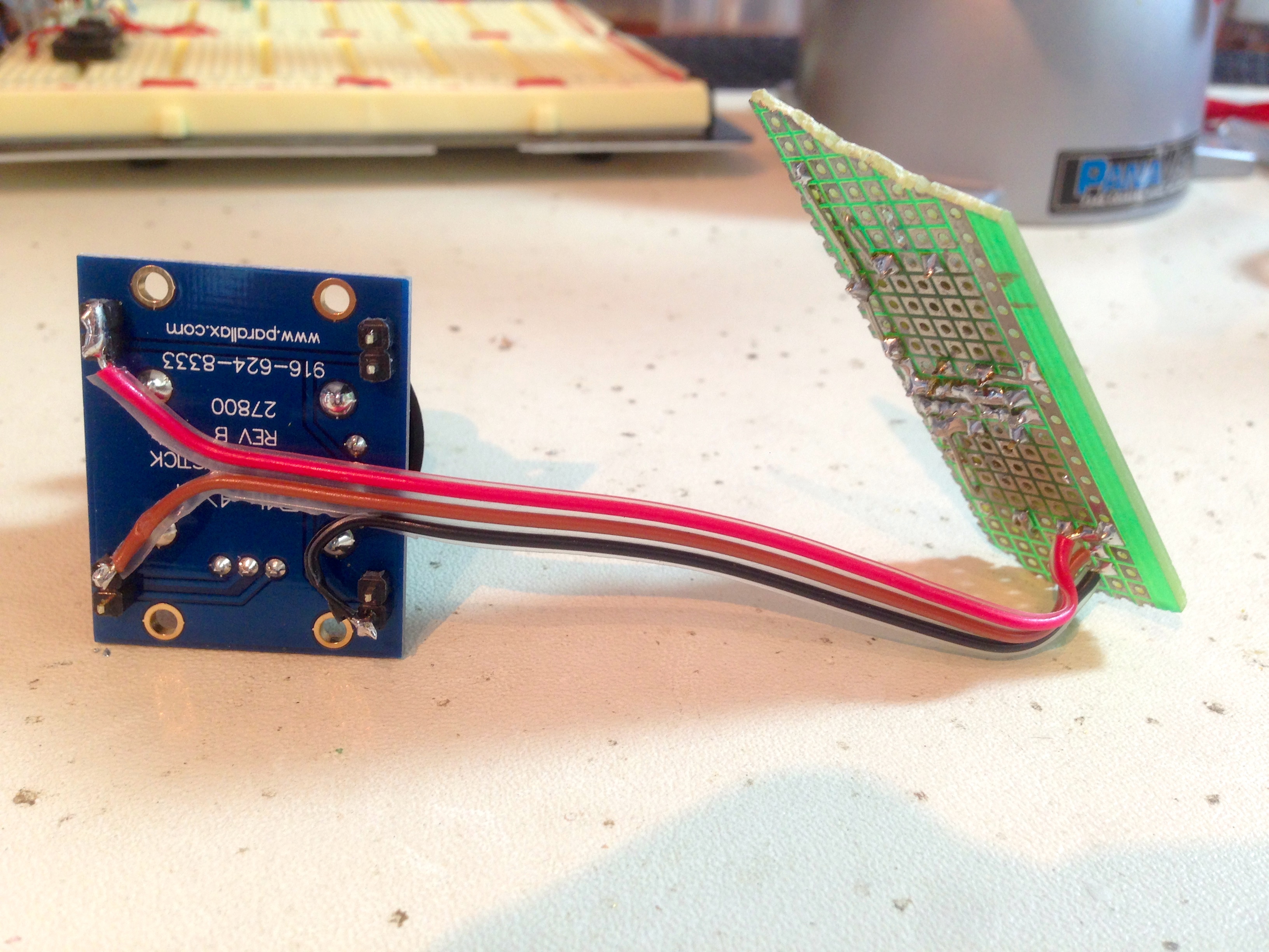
We need three wires to connect the joystick (+5V, horizontal sense, and vertical sense), and we need to connect the 9-wire harness coming in from the Apple II. It seemed easiest to use the PCB as the common point for all this wiring, so I ran a small harness between the two halves.
Next up we need the cord. Normally, I would do what a proper hacker does and make my own cable. However, the economics of cabling in the modern globalized economy are staggeringly perverse. The fact is, I can buy a perfectly well-made 6ft 9-pin cable for less than it costs to acquire the supplies to make my own. Never mind the time and the fact that a homemade one would not be as nice or as strong. Weird as it may seem, it’s cheaper and better to simply buy a commercial cable and cut it apart.
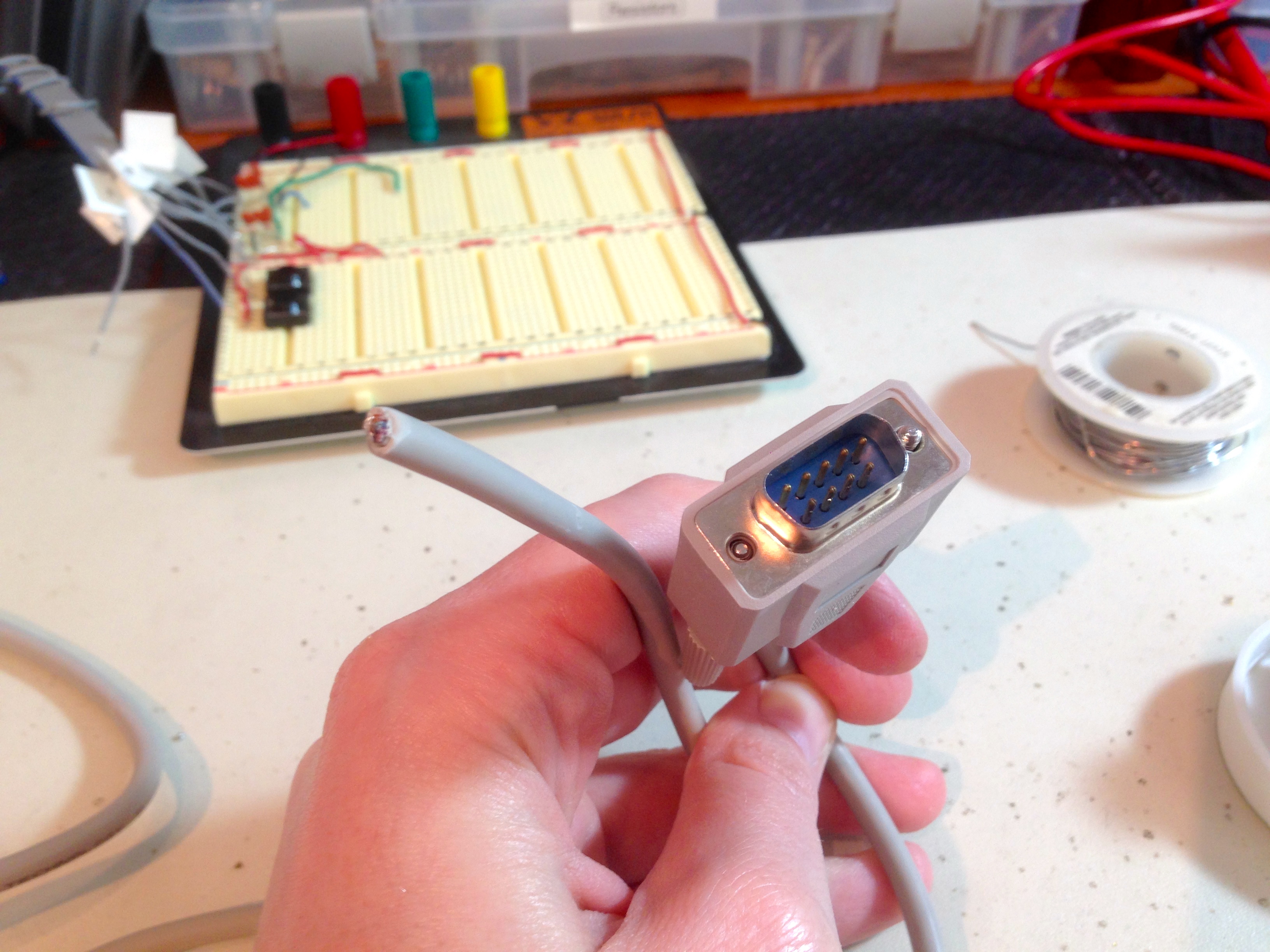
Next up, I needed to get out the meter and figure out which pins went to which wires. Luckily, in the prototype, I had taken the time to label my wiring with the numbering scheme used on the Apple II port. That made it easy to ensure everything on my new cable is going to the right place. This is critical, because a mistake here could fry chips inside my precious Apple IIc Plus. A triple-checked everything, but I confess there was still pucker-factor when I plugged it in and powered up for the first time.

Finally, we need hardware. The junk pile coughed up a nice selection of small self-tapping screws, which work great in 3D models. Print a 2mm hole in the middle of your mounting posts, and you can easily screw things in with whatever small screws you have lying around. I always keep the tiny screws from things I take apart. They require virtually no room to store, and might be incredibly useful someday. Like today.


I’m very pleased with how the final device turned out. It’s imminently usable, sturdy, compact, and thanks to open-source 3D printing, you can make one yourself. If was going to change anything, it would be the overall shape. It looks nice to my eye, but it’s not super comfortable to hold for long periods. It needs more rounding of the edges and such. It makes you appreciate why big commercial game controllers like the Xbox and Playstation have such elaborate organic designs. They need to be thick to accommodate analog sticks (like mine), so they hide that thickness in smooth drawn out shapes that are easy to hold (not like mine).
Enough talk, though. As the old saying goes, “The proof is in the Lode Runner”. Does my Apple II Gamepad perform in the field? Only one way to find out.
Yep.
Quinn,
As always, a great explanation of the build. Thanks!
Any new tool opens up possibilities, and 3d printing, like CNC machining, is just the next step up. Things you might not have considered before are now within reach. Plus, you learn a bunch of stuff, have fun, and just roll with the goof ups.
Love the honesty you put into your explanations. It makes it easier to laugh off occasionally burnt fingers!
?;-)
That tool is called a 5-in-1, and you’ll find in the paint aisle. When I did a summer painting, one lived always in my back pocket.
It’s good for small bits of scraping, opening paint cans, and that curved bit is used to scrape paint out of a roller when you want to clean it.
Aha! Thank you! I couldn’t figure out what that weird shape was for. 🙂
You are taking the lie that was the portability of the IIc and making it real, only 30 years later.Totally awesome. I think the solution is quite elegant, though somehow you resisted the urge to make a PCB for the button part.
This series of apple II articles inspired me to try to solve the Apple IIgs display problems I had mentioned on my comment before. I realized my parents did have a nice RGB monitor, and I just needed to make a custom cable for it. Of course I had to over-engineer the cable and make a custom PCB… http://blog.andyselle.com/2015/06/17/a-rgb-display-for-an-apple-iigs/
I still would like to make the end-all-be-all scan doubler using a FPGA, but not today…
That’s great- thanks for sharing! Glad you found a monitor for the IIGS. That machine just isn’t the same without a proper 15Khz analog RGB display. In case I haven’t mentioned this before, a lot of people use arcade video converters with good success on the GS. The GS basically has arcade video (ish), and there are some boards designed to adapt 80s arcade boards to VGA monitors that work well.
I have long wondered whether an Amiga 15KHz analog RGB monitor like a 2002, 1080, or 1084 could sync to IIgs video. But I have yet to find a definitive answer.
Yep, you definitely can. Commodore made some great monitors, and the Amiga ones support all kinds of signals. Here’s how to make a cable for the IIgs:
https://groups.google.com/forum/m/#!topic/comp.sys.apple2/AhUBiEcp0sU
Where is the “buy now” button???
Heh, I am considering offering these for sale, there’s enough interest in the Apple II community. I need to refine the design a bit more and would need to source some components.
Yeah, warping is one of the problems with ABS, but I’ve had it with PLA as well. I don’t remember if the Printrbot Metal has a cooling fan that blows on the bed, you NEED that for PLA.
Now what us RepRap guys do is to clamp a piece of glass to the top of the bed with Bulldog clips and print on that. If you are using the ABS slurry you DON’T need or even WANT the Kapton tape on the glass. Just pour a small pool of acetone on top of the glass and then rub a failed ABS print in it spreading the molten ABS evenly all over the glass. That’s the easiest way to make your slurry. It might even be a good idea to start heating the bed first so you are spreading a warm slurry and the excess acetone will evaporate.
Using the glass clamped to the bed has the advantage in that it is removable. Now you can take the glass with your print off the printer and put it in the ‘fridge to cool it. Once it gets down to about 40F the print should just fall off the glass, or only need a swift Karate chop to remove.
One more thing, ABS shrinks as it cools so your print might end up too small by a few percent compared to the same model on the same printer done in PLA. Just like casting metal, you need to make the mold, or the cad model a bit larger to compensate for the shrinkage. How much? You’ll have to experiment, but it will be somewhere between 0.5 and 2 percent, at least that’s what I’ve seen so far.
It’s this shrinkage that causes the warping, which is why a heated bed is needed for ABS, and not just to get the print to stick to the bed. For large prints you might need to put the entire printer into a closed heated box to keep the entire print at the same temperature during the entire print operation. For small items the heat rising off the bed will normally be enough. Just keeping drafts of air away from the printer might help (turn off the A/C?)
Looks like a fun project. Is that the largest thing you’ve printed so far?
I just got a Printrbot Metal Plus as well. I think you may have been one of the last to get it as a kit. When I looked a few weeks after you posted about yours, the kit was no longer available. I contacted them before I got mine, and they said they discontinued it because the assembly was too complicated, which I guess was causing support problems.
Do you have any links or references for how you’ve learned to “tune” your printer? I’ve been having a hard time finding much information about how. My printer certainly works, and I think I’ve got the Z offset (M212) calibrated properly, but my prints all come out stringy, with adhesion problems between the layers occasionally.
That’s a shame, because the kit was a lot of fun to build. They could have reduced support problems by keeping their instructions up to date (there are a lot of mistakes) and having better quality control (I had some incorrect parts that were show stoppers).
As for tuning, I just google a lot. PrintrBot has forums that are active with advice, as does the rep rap community.
Stringy prints are caused by running the nozzle too hot. For PLA, I use 205 nozzle and 70 bed. That works well for me. For ABS, I’m currently using 230 nozzle and 80 bed (with slurry), but I’m still experimenting a bit. ABS is more challenging to print well, but has nicer results when you get it right.
Adhesion problems between layers are generally caused by the bed being out of level and/or by differential cooling. Use the depth-stick on a caliper to get the bed parallel to the X carriage as close as you possibly can to perfect. Within 0.05mm is good. For differential cooling problems, you need to control the temperature around the printer. Enclosing it somewhat, for example, or putting it in a quiet room with no breezes coming through. People say putting cardboard around the sides of the printer helps a lot, but I haven’t tried this. Leave the top open so the machine doesn’t overheat. I lock mine in a quiet room and that seems to do the trick. The fumes build up a bit, but that’s what the lab is for. 🙂 I crack a window, and for long prints run a fan on low to exchange the air a bit. Not too high so as to create a breeze near the printer. Again, the cardboard would probably be a good idea here.
I’m far from an expert at this, but these are a few things I’ve picked up so far. This is definitely not the largest thing I’ve printed. That would be the ATX power supply case I talked about a couple of posts ago. That thing filled almost the entire build volume of the Metal Plus, and was a very challenging print. I ended up doing it in pieces, rather than trying to get the whole massive thing to print in one go.
Thanks for the advice. Specifically for the suggestion on the way to measure it. I would have never thought of using the caliper that way. I didn’t realize that’s what that metal rod that comes out of it is. 🙂 It looks like my bed is already level to within about 0.03mm as I measured it.
At your suggestion to control the temperature better, I’ve surrounded my printer with the cardboard box it came in, on three sides. The side that isn’t covered is the side the fan on the head tends to blow air in, and the window to the workshop (with a fan in it) is on the side that’s best shielded, so it seems to block any breezes from getting to the printer. Since doing that, I’ve been having much better luck! PLA is coming out really well now (at 205, rather than the default 210) and I’ve even been having pretty good luck with ABS, though the prints do delaminate with enough force. I haven’t experimented at all yet, but I gather that I may be printing at too low a temperature for ABS. (215 is what I was using, I think. I need to move my notes from the paper notebook at home, to something online.)
Oh yeah, I the ATX case. The latest Printrbot Plus are coming with a metal case for the power supply, with what’s supposed to be a spool holder on top. Unfortunately, it’s too thick for any of the spools I have.
http://3k8g8c3p564l1zjnb621d3aoii6.wpengine.netdna-cdn.com/wp-content/uploads/2014/09/Metal-Power-Tower-w-Universal-Spool-Rack.png
Thanks again for the advice, and the the awesome blog.
215 is definitely too low for ABS. As for delamination from pulling on the parts, well, that’s just 3D printing. 🙂 There’s a limit to how strong these parts are. The cool thing about ABS is that you can seal the outside with acetone. You can either brush it on or pour it on and rinse it off. That seals the layers together and greatly increases strength. Increasing fill density also helps with strength, because you have more contact area between layers.