Taking classic gaming on the road.
Teddy Top has been proceeding nicely, and my IIc Plus is getting increasingly portable. However, there’s one key thing still missing- a joystick! In its current incarnation, my Teddy Top-equipped IIc Plus will be great at KansasFest for, say, writing a term paper or doing my taxes. If we’re being honest, however, most of us used these things primarily for playing games. Most of the best Apple II games required a joystick, so any road warrior IIc needs one. The best Apple joysticks where things like the CH Products line, or Apple’s own variants. These all have one thing in common- they’re analog. In an age when most joysticks were digital (arcades, Commodores, Ataris, etc), Apple went a different way. Some things never change. The rest of the world has caught up since then, and nowadays, no gaming system would dare go without some analog control elements. There’s just no substitute for the feel and control of an analog joystick. It would be nice to think that the analog Apple joystick was the result of brilliant forethought on what would be better for gaming, but actually it’s just because the Apple II was originally designed with paddle controllers in mind. Steve Wozniak basically designed the Apple II to play his favorite game, Breakout. Paddles are best for that, and adding two made sense for games like Pong as well. Once you have two paddles, you have the makings of an analog joystick (each paddle is an axis). The downside to this is that you only get one joystick out of two paddles, which is not great for multiplayer. This is one of many reasons why other machines were better choices for gaming, but we Apple people liked it just fine anyway thank you very much and who needs sound anyway and we like our six weird colors and sprites are dumb and we don’t want them and shut-up. Sorry, had a little flashback there. I’m good now. The point is, as nice as these old analog joysticks are, they are bulky and definitely not road-warrior-compatible.
Nowadays, we have modern gamepads with very slick and compact analog sticks in them. What I want to do is build one of these for the Apple II. This is one of those ideas that I had that I thought was pretty clever, but then googled a bit and realized lots of other smart people have already done it. Nevertheless, I’ll give you my take on this project, and maybe it will be of some value. At the very least, it gives me a chance to take some cheap shots at Commodore and Atari.
One way to get started with this would be to rip apart an old Xbox or Playstation controller. They have very nice analog sticks in them. If you don’t have one of those lying around to cannibalize, Parallax sells a very nice one for an astonishingly reasonable price. I went this route, and I’m very happy with it.
Now we get to the technical problem. As you might expect, the analog paddles (and now joystick axes) are just a simple linear potentiometer. The world is filled with those, right? No problem, right? Well, much like the dreaded DB-19 connector problem, the analog game inputs rely on an obscure variation of an otherwise common part that is no longer available. For some reason, they decided to use 150kΩ potentiometers. You might not expect it (I didn’t), but it turns out nobody makes anything in this size anymore.
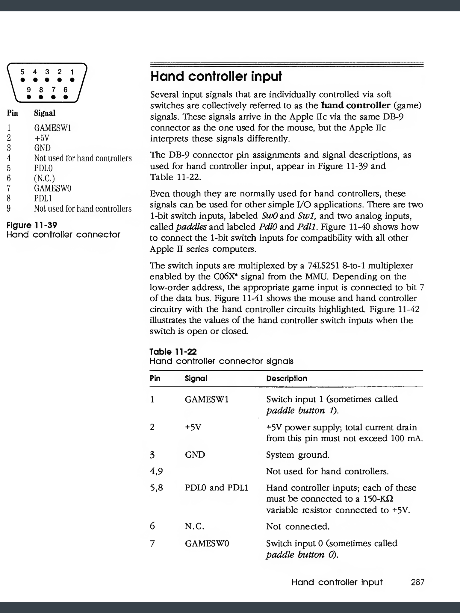
I’m getting ahead of myself here, though. Let’s start by setting up our prototyping platform for this device and see how we get along. First we need a cable. I’ll be focusing on the IIc, IIc Plus, and IIgs, which have an external 9-pin game port. Earlier models have an internal DIP-socket-style game port with different pinouts. However, if you have room to carry an Apple IIe, you have room to carry a joystick, so this gamepad design is likely of limited value. To begin with, we need the connector in question. Luckily, unlike the dreaded DB-19, nice IDC DB-9 connectors are still readily available.
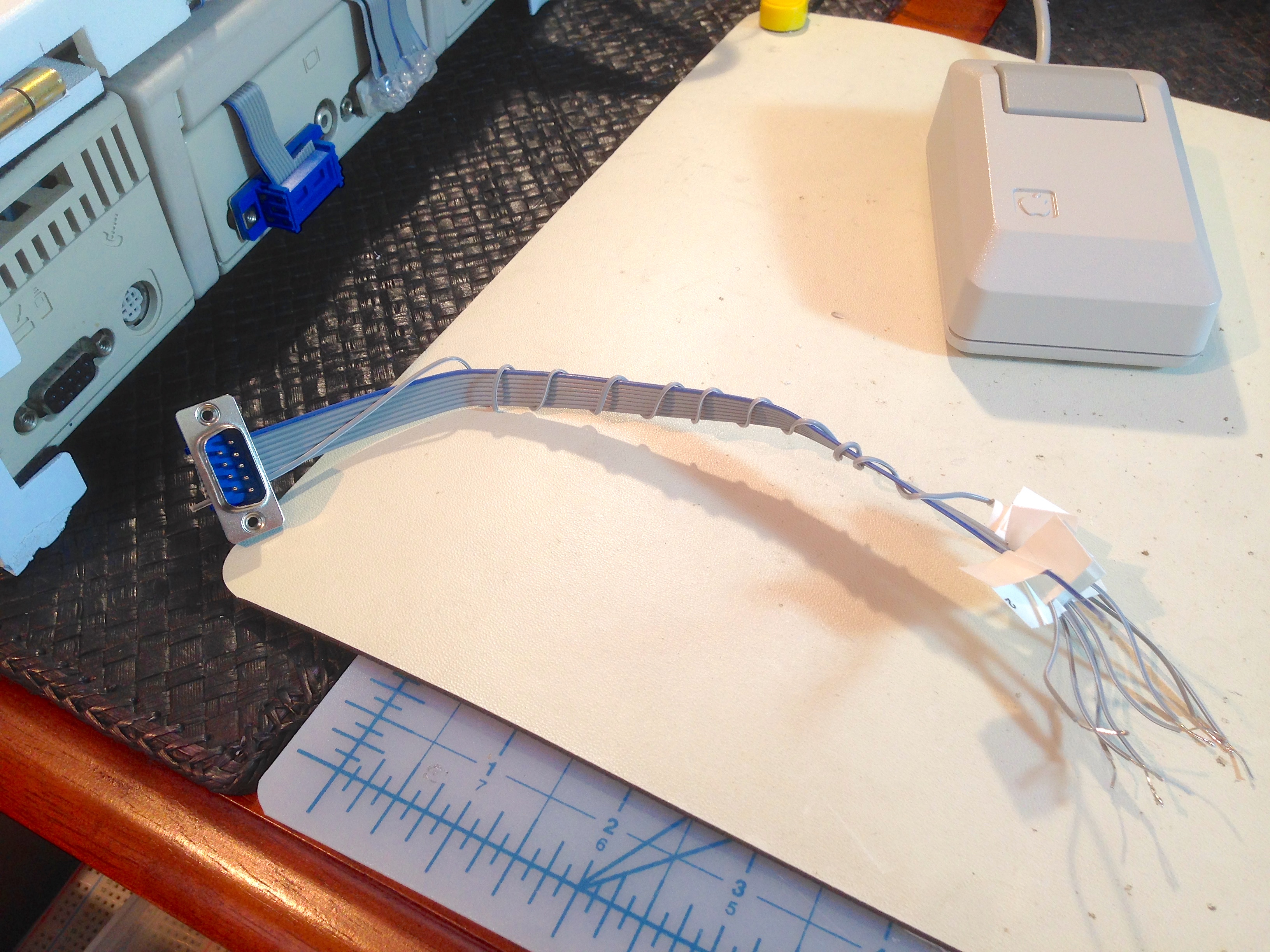
I took the extra step of labelling all the wires to prevent errors later on. One downside to IDC connectors is that they alternate the wires on different rows as you count across the ribbon cable. This makes perfect sense from a physical design standpoint, but does make it tricky to keep wire and pin numbers straight in your head. Especially when referencing documentation, which likely numbers the pins based on looking at the port, not the connector. That flips everything around even more. I did these mental gymnastics once, and labelled the wires to match the documentation. Speaking of documentation, the Apple II has tons of it.
We’ll start with the buttons (of which there are two, because Apple is better than Commodore and Atari). You might think these are just switches, but it’s slightly trickier than that. Referring to the schematics in the documentation, we see these are actually TTL inputs.
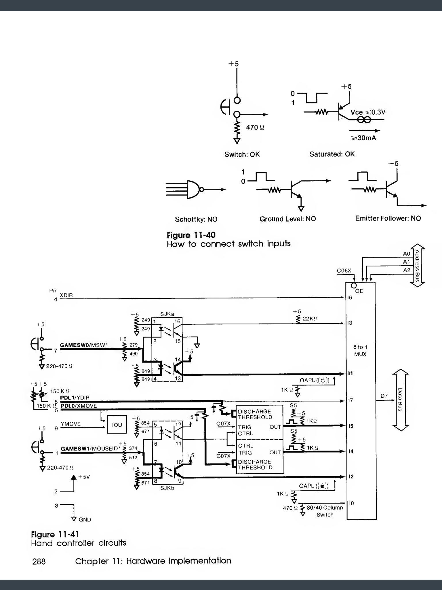
The takeaway from this is that the I/O multiplexer has an opto-isolator protecting itself from our switches (cool beans), and it expects a 470Ω pulldown resistor to drive the input low when open and high when closed. This part is easy, so let’s wire it up and give it a go.
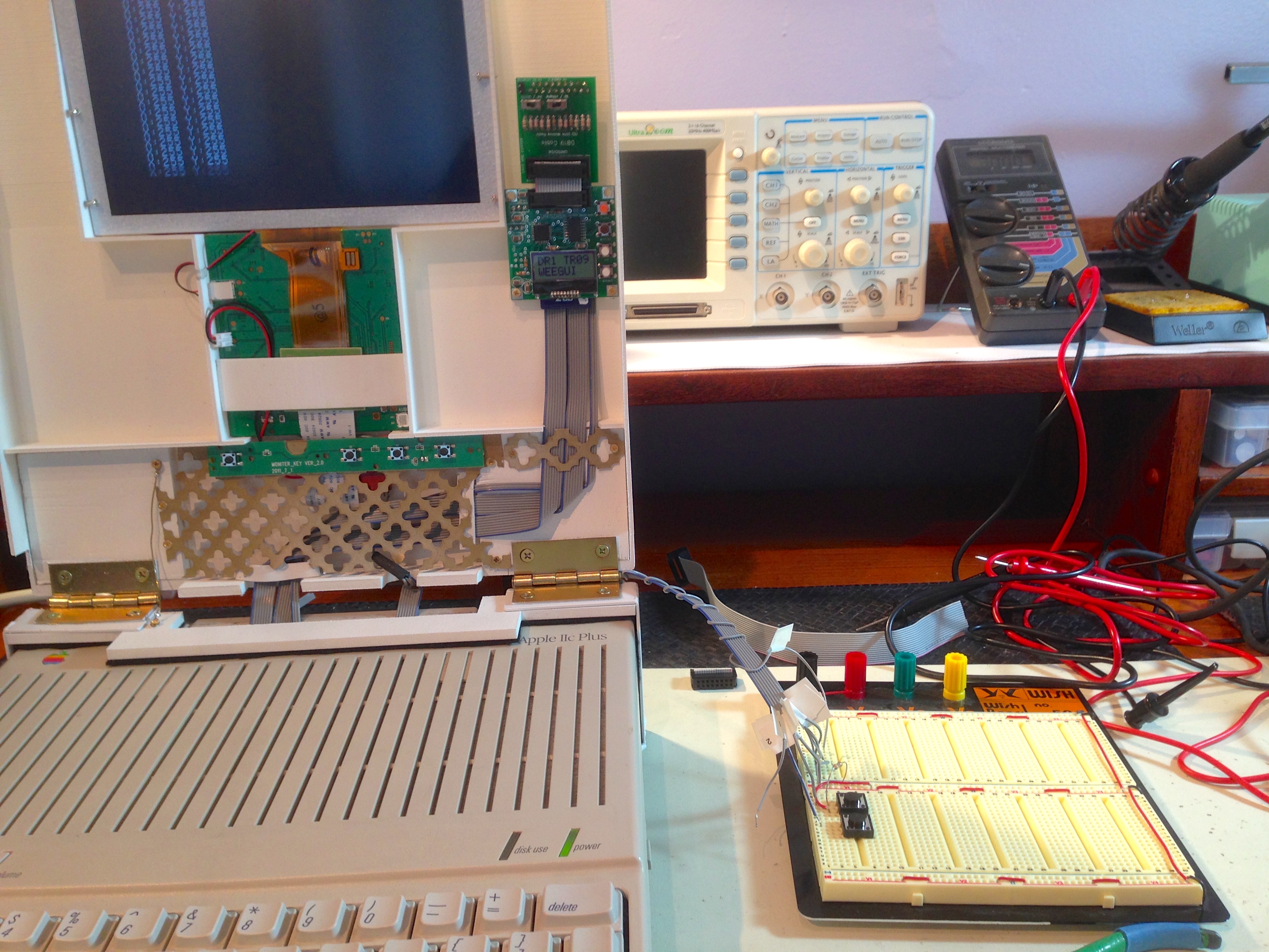
Now to test it. For this, it’s AppleSoft BASIC to the rescue. These vintage microcomputers absolutely beg you to program them. Unlike modern machines, where you spend days installing things and reading documentation before you can write a Hello World, the Apple II literally turns on into a state where you program it. Here’s a quick AppleSoft program that I’m using to monitor the game port. There’s a byte displayed for the X-axis reading, and the Y-axis, and each button is shown when pushed. You can turn on the machine, type in this program, and solve a problem within 45 seconds. Let’s see you do that with Xcode or Visual Studio. Also, get off my lawn.
 10 A =  PDL (0)
 20 B =  PDL (1)
 30 C =  PEEK (49249)
 40 D =  PEEK (49250)
 50  PRINT "X:";A;" Y:";B;
 60  IF C > 127 THEN  PRINT " 0";
 70  IF D > 127 THEN  PRINT " 1";
 80  PRINT
 90  GOTO 10
Now that we have the obligatory cranky-old-woman rant out of the way, let’s see how our buttons are doing.
Hooray! That worked. With the easy part out of the way, let’s get back to that potentiometer problem I talked about. Here’s what happens if we hook the Parallax joystick directly to the analog inputs on the game port. In this video, I’m running my test program and moving the joystick up and down.
You can see the Y-axis changing, but barely. This is because this joystick’s potentiometers are the wrong size. As I alluded to earlier, we need a 150kΩ pot, but these days you can only get them in simple order-of-magnitude denominations like 1kΩ, 10kΩ, 100kΩ, etc. The Parallax joysticks, for example, are 10kΩ on each axis. It’s not possible to passively scale a potentiometer’s range, but we can take advantage of how the analog inputs on the Apple II actually work. Let’s take a look at that circuit, using a portion of the schematics of the entire machine provided in the manuals:
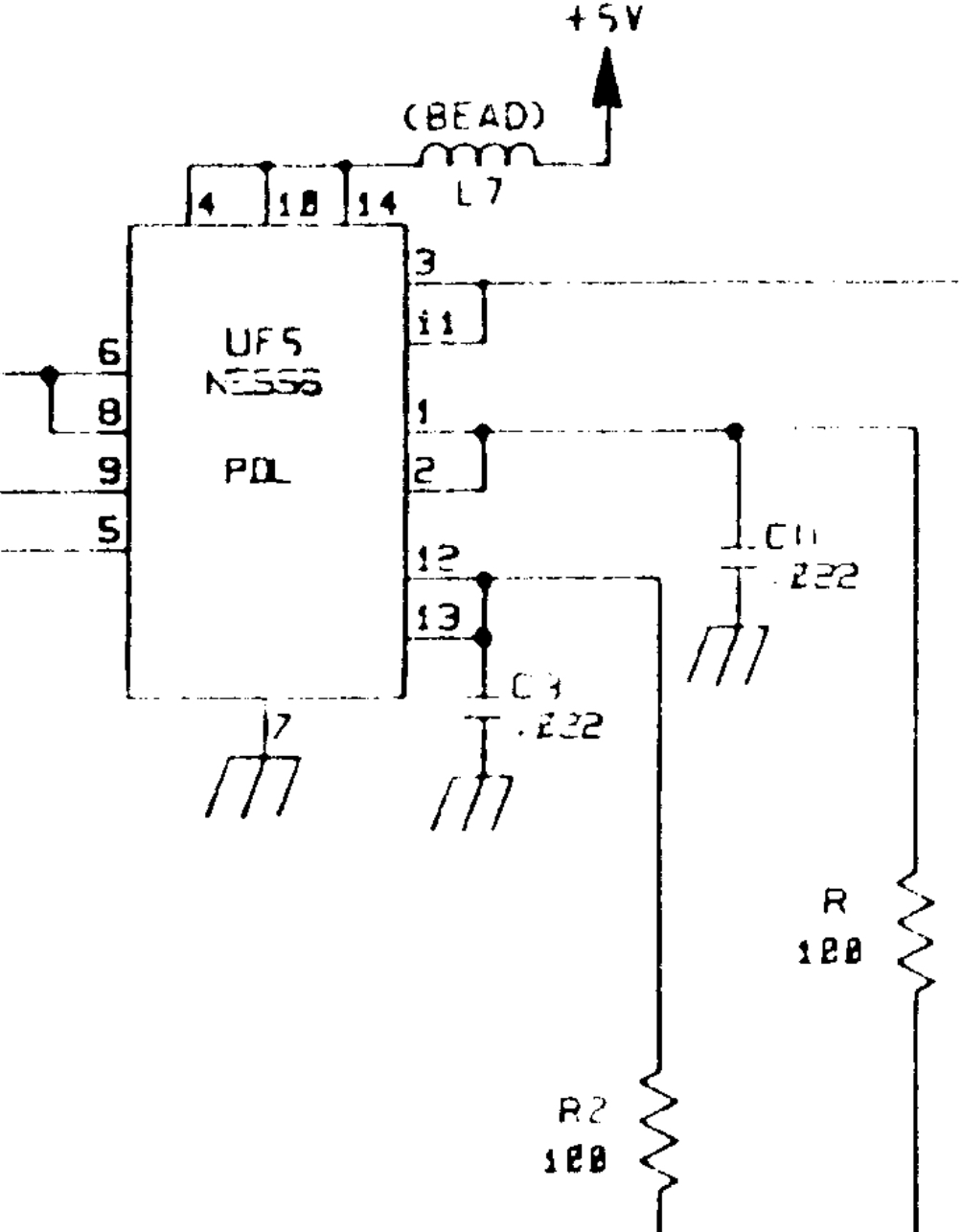
The resistance in the paddle is used to modify a pulse train being generated by a 555 timer. Since there are two paddles, there’s a 556 chip holding a pair of 555 timers, and two RC circuits. This approach leads to some interesting quirks. For example, it means higher paddle values need to be read less frequently, because the capacitor needs time to discharge and recharge. Most programs compensate for this by reading the paddle less frequently for all values, at the cost of some responsiveness. This is rarely a major problem in real life, but it’s an interesting property that can be observed in fast assembly code.
Anyways, this pulse counting design is great news for us. While we can’t get our joystick’s resistance into the range the Apple wants, we can fool the timer circuits to work with our joystick. A little math and a few extra passives is all we need. As long as the pulse train speeds up and slows down the same amount as it used to, the actual values of the RC circuit don’t matter. Since our resistance is different, we can modify the capacitance to compensate. We know from the schematic above that the Apple has a 0.022μF cap in the circuit, and the paddle’s normal maximum is 150kΩ, so we can solve for how much capacitance we need to add. The time constant (R*C) needs to be the same before and after our additional capacitors are added so that pulse train behaves the same way. This gives us:
10kΩ * (x + 0.022μF) = 150kΩ * 0.022μF
x + 0.022μF = (150kΩ * 0.022μF) / 10kΩ
x = (150kΩ * 0.022μF) / 10kΩ – 0.022μF
x = 0.308μF
For our 10kΩ joystick, we need just need to add 308nF of additional capacitance, and we’re golden. This is particularly easy, because capacitance adds in parallel, and we know from the schematics that the capacitor in the RC circuit sits between pins 5 and 8 on the game port and ground.
I don’t happen to have a 308nF capacitor kicking around, but I do have a bunch of 100nF and 10nF caps, so I can get us very close. Let’s try it out.
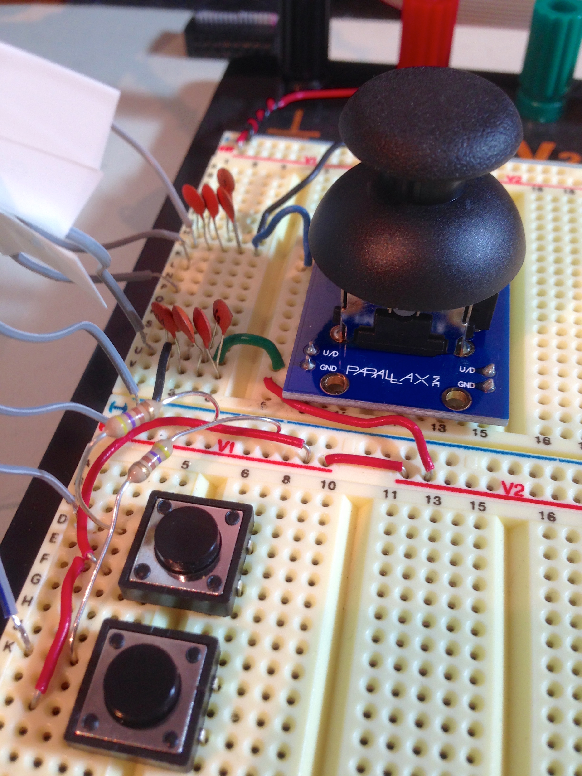
Now only one thing to do- try it out!
Here’s a test of both axes and the buttons. Note that, at rest, the values sit close to 128 (as we would expect), but the X is a little off. This is why most Apple II games have a joystick calibration step when you start playing. Every joystick is a little different in the real world, so this little discrepancy is of no concern to us.
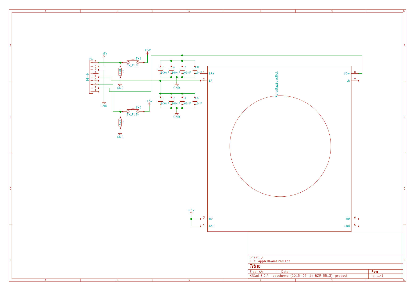
Now we have something we can build. Here’s the final schematic.
This is all well and good, but there’s really only one true test of this device’s effectiveness. Every new piece of hardware needs to go through a rigorous scientific process known as The Lode Runner Protocol.
Result! It’s worth noting that this is the first time in about 25 years that I have played Lode Runner on real hardware. I have to say it’s as good as ever. The author, Doug Smith, passed away recently, so do yourself a favor and give it a try in his memory.
Next we need an enclosure for this. I have some plans cooking for that, so stay tuned.
Back in *my* day a controller port on my Atari could handle 2 paddles and 5 buttons at the same time. Joysticks were digital and used 4 buttons for direction and one for firing. And paddles each had a button that used the same inputs as left and right. An analog joystick with 5 buttons would be no more work than wiring it all together. I think the paddle inputs were even a simple voltage divider.
And because they were attached directly to the PIA the 4 direction pins could also be used as outputs. That’s how they did the 12 button keypad controller. 4 strobe lines and 3 inputs – 2 of them the paddle inputs used in a binary style. All the interesting bits were done in software and the controller was just a matrix of dome switches.
Oh, and there were 4 of those ports.
Also, you have an excellent lawn and they should respect that.
Haha, I wondered how long it would take for a comment calling me out on my propaganda. Didn’t think it would be the first one. :-p
It’s a 35 year old automatic response that got triggered.
Being an Atari owner in a crowd of Apple owners required a lot of explaining.
I got pretty deep into the home computer wars back in the day, and it’s funny to look back on it now and see how silly it all was. It’s interesting to me how the human tendency for tribalism is so strong that it drives people to anger over arbitrary consumer product selection. You still see it today with Android vs iOS, and other areas. Anyways, I like to make fun of it now, because of how ridiculous it obviously was in hindsight. Such a waste of energy.
Nonetheless, we Apple II types always won the argument did we not? 😉
Of course one could argue that why do you need bi-directional joystick ports when you have the full address and data bus available in the form of 8 internal slots 🙂
As a kid, we were an Atari house — I had a 400, 1200XL and 65XE before moving on to other platforms. I never really got the appeal of the Apple II then, because to me it looked like a horrible gaming machine (for all the reasons Quinn mentioned above). But later on, as I started to dig more into how computers worked at the lower levels, I definitely appreciated the open design of the Apple II.
That said, I still have fond memories of my Atari as well. No need to fight — they can both sit side by side on my desk.
Now those Commodore folks… 😉
Called it. 😛
Yup. 🙂 In fact, it was already in the works when you posted that comment. Great minds think alike? Then again, so do chickens. Hmmm…
We’re GREAT CHICKENS!
Us Commodore folks were very happy. We had GEOS by 1986.
Although an analog stick would be useful when trying to navigate hordes of natives in Seven Cities of Gold.
GEOS was so awesome. Of course, Apple people maintain the Apple II version was vastly superior. 😛
Other GMTA moment here. I had the exact same flashback here with just ONE word of difference:
“This is one of many reasons why other machines were better choices for gaming, but we CoCo people liked it just fine anyway thank you very much and who needs sound anyway and we like our six weird colors and sprites are dumb and we don’t want them and shut-up. Sorry, had a little flashback there. I’m good now.”
for the enclosure id look at gutting a nunchuck for the wii, desolder buttons and joystick, then replace the board(s) and cabling with your own. would also be a very small device to make it more portable. i recently attempted this with a ps2 controller to turn it into a r/c controller, failed horribly due to cheap chinese atmega knockoffs (need to source parts from places more reliable than ebay).