Bushings and ells and plugs, oh my!
I used to think a boiler was a big metal shell that you pressurize. That’s a good description of an air tank. However, a steam boiler is really a system that has the pressure vessel as one part of it; but there is so much more. A steam boiler is more like a fancy way to store a hundred fittings. Because holy cow are there a lot of fittings needed to make a functioning boiler system. You can buy most of these in the plumbing aisle of your local website, but I decided it would be much more fun to make them all from scratch. That was a really great idea until around fitting number 86. Then it got old. Okay, I’m hyperbolizing here, but that’s my prerogative as the sole proprietor of this blog.
I really like working with brass in the lathe, so this was a great opportunity to do a lot of it. 360 free machining brass is really easy to get a beautiful finish on, and you don’t need cutting oil or coolant for most operations. It also makes very nice chips, so cleanup is a breeze. Surface speeds are generally low, so the lathe is running quietly, which I enjoy. It’s basically the opposite of aluminum in every way, which is why I really hate machining aluminum.
To make plumbing fittings, an easy route is to start with hex bar stock of the size that you want the “wrench” part to be. The rest of the fitting is machined down from there. Pretty much every fitting here will have a hexagonal section, because I want to be able to use two wrenches at each connection to avoid stressing braze joints and such.
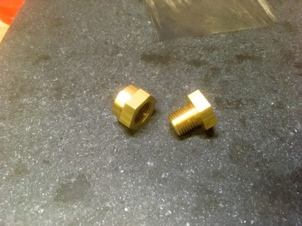
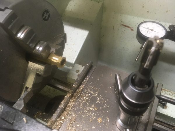
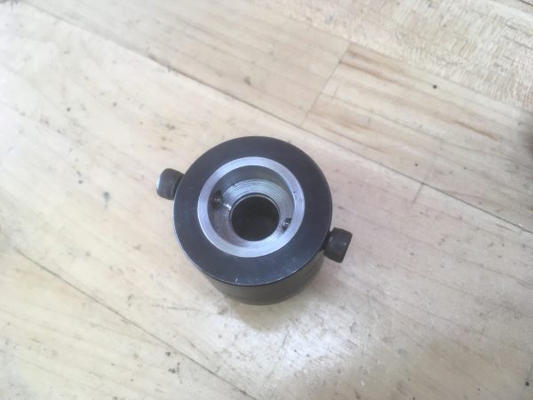
To get my feet wet (pardon the pun), I decided to start with the fill plug at the top of the boiler. This is super useful, since at the moment all water is outside my boiler and at some point a portion of the earth’s water needs to be inside it.
Now for the bushing part of the filler. This is a straightforward part as well. Parts like this are where you really appreciate seeing your own skills in the machine shop develop. When I first started, a part like this would have taken me a couple of hours. I can now knock out a basic plumbing fitting in a few minutes. You gradually learn all the million little work habits that slow you down, and you learn which parts of the setup are important and which are not. The more you learn exactly where to apply precision (and thus time), the quicker you get.
The bushing (or boss, if you like) has a round part that goes inside the boiler shell. This is the surface that will be brazed. The hex area is to put a wrench on for tightening the plug without stressing the braze joint.
The next set of fittings to make are considerably more complex. These are for the water level gauge. It’s super important that the water level in a boiler never drop too low. In the case of this boiler, it can’t drop below the level of the heating element. The heater is designed to be fully immersed, and it will burn itself out if exposed to air while powered. The traditional way to monitor water level in a boiler is with a sight glass. In this case, it’s a glass tube the same height as the shell, which is plumbed in to the top and bottom. This tube is pressurized with everything else, so it needs to be pretty sturdy.
The water gauge itself was ordered from PM Research, a supplier of scale steam components. I considered making this from scratch, but the glass has to be borosilicate to cope with the temperature and pressure changes, and that stuff is really expensive. It was actually about the same price to buy the whole gauge from PM Research. Gauge in hand, I only needed to make fittings to connect to my boiler.
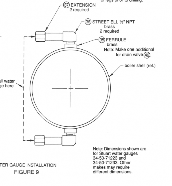
Each half (top and bottom) needs a mounting boss, an elbow, and an extension pipe to reach out to where the gauge sits.
This is a good moment to pause and talk about pipe threads. In North America we have the NPT, or National Pipe Thread standard. What’s interesting about this is that the threads are tapered. This makes them self-sealing against liquid and gas pressures, because as you tighten them, the threads wedge together as much as needed to stop leaks. With a normal straight thread, the tolerances of the thread cutting mean there’s a path all the way through the fitting where gas can escape. A common misconception is that the hole (or pipe) for a pipe thread is itself tapered. In fact, the stock is straight. Only the threads themselves are tapered. A diagram will help.

This “tapered thread in straight stock” profile makes these threads difficult to cut. Pipe thread taps are always really beefy for this reason. For proper sealing, you need at least double the nominal dimension of overlap (in this case 1/4″ for 1/8″NPT thread) so you have to make sure to cut deep enough. In my experience, “deep enough” is usually a bit past where you’re really having trouble making progress with the tap and/or you’re starting to get concerned about breaking it. It helps to mark the needed depth on the tap so you know before you start. I opted to standardize almost every fitting on this boiler at 1/8″NPT. It feels like a nice size for this application.
Let me pause to head off the comments, here- pipe threads are actually a really complicated topic that I have oversimplified for brevity. There are different forms for low-pressure, high-pressure, structural, dry-seal, putty-seal, and all sorts of others. Some pipe threads are straight threads cut into tapered stock. However, the basic NPT form I describe here is mostly what people mean when discussing pipe threads.
For these elbows, I decided to buy them. They would have been easy enough to make, but some reason I decided to make them with my Amex this time. This form of elbow is called a “street ell” on the streets. A street elbow has one male and one female end, which is handy for making extensions like we’re doing here.
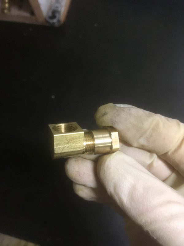
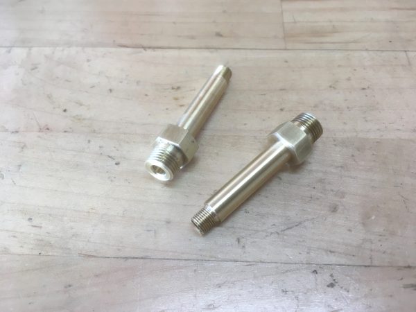
The last part of the water gauge system is the extension pipe, and this is the most interesting fitting. I decided to make it look like a pipe with a narrow hexagonal section in it for wrenching on. One end is 1/8″NPT to mate with the street elbow, and the other end mates with the water gauge.
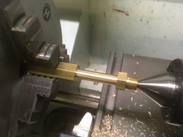
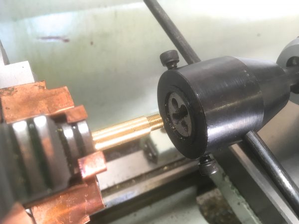
Threading the small end got interesting, because it’s not a typical thread. The water gauge is a model engineering part, so the thread is from the class of weird little threads that model engineers have come up with. In this case, we need a ¼-40 thread. That’s a teeny thread that has a corresponding teeny die to cut it. I cut all my threads using a tailstock die holder that I made as an afternoon project. It works great, but it is sized for 1″ round dies (the most common size). I could only find ¼-40 thread dies in the smaller 13/16″ size.
As I’ve often said, the great thing about machine tools is that any time you need a new tool, you can make it. In this case, I needed an adapter for 13/16″ thread dies to go in my 1″ holder. Let’s make that!
This is a nice simple lesson in accumulated error. If all the surfaces on this adapter aren’t as flat, true, and square as we can get them, the die held in the adapter will introduce error to the work that the original tool did not have. Imagine if Lego bricks were made haphazardly, for example. Two walls of twenty bricks would come out a different height, and you couldn’t put a roof piece across the top of them. That’s accumulated precision error. Lego bricks are made to an astonishingly level of precision, not least for this reason. Accumulated error in any dimension would ruin the whole system in short order.
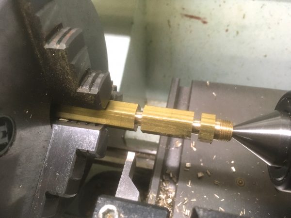
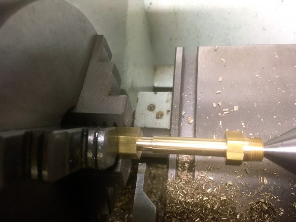
With that snazzy new tool made, I was able to finish the extension pipes for the water gauge.
The last fitting to be made in this batch is an elbow for the bottom of the boiler. This is to attach the blowdown valve. Boilers boil water (no, really!) and boiling water pulls minerals and other impurities out of it. These impurities collect inside the boiler and reduce the efficiency of it. You want to clean these out periodically.
One of the interesting things about cars is that they manage to do every job in the car using gasoline. Windows move by electric motors powered by an alternator driven by a belt off the crankshaft. Thus gasoline moves your windows up and down. The typical car heater works by piping hot engine coolant through a radiator core, and this coolant was heated by the engine’s combustion, which comes from gasoline. Thus your heater is powered by gasoline. Yes, there are exceptions, such as old air-cooled Volkswagens burning gasoline for heat, and using spare tire pressure for the windshield wiper. But in general, you use the power you have on board.
Steam locomotives and stationary boilers are the same- they have creative ways to use steam to do every job they need. In the case of cleaning impurities, we have the blowdown valve. Since the impurities are heavier than water, they settle to the bottom. While the boiler is under steam, we can crack this valve at the bottom of the tank and the steam pressure will blow all the impurities out the bottom (along with a bunch of scalding water- steam engines are not for amateurs). Note that there are also surface blowdown valves on some boilers, because the water/steam interface is where a lot of dissolved impurities collect during operation. For this basic little boiler, a bottom blowdown is all we need. The bottom blowdown valve is also the drain when we’re done playing.
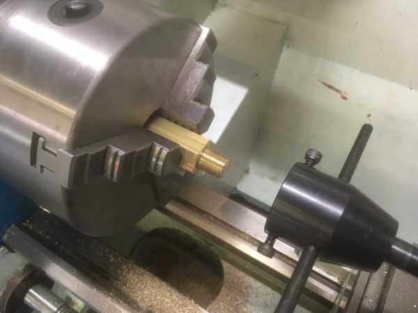
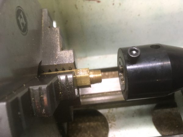
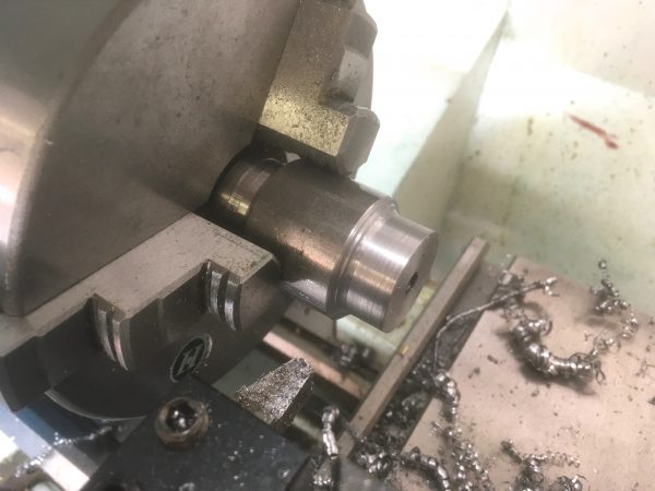
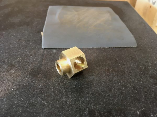
Since my boiler doesn’t have a lot of clearance under it, I need an elbow to get the blowdown valve out to where it can be reached. I decided to make an elbow fitting that can be brazed directly into the shell.
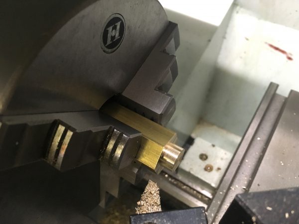
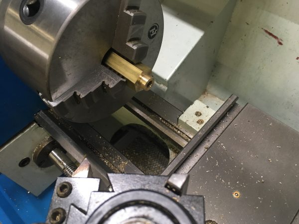
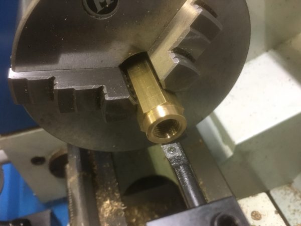
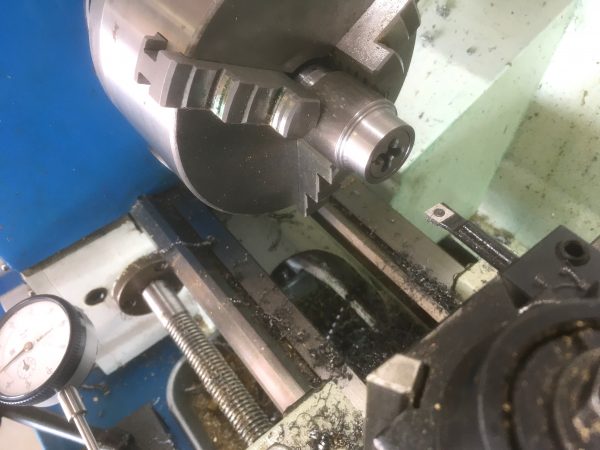
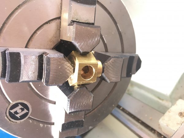
Next I needed to flip it 90° so I could drill the other opening. This was a job for the four-jaw chuck.
I also made a bunch of 1/8″NPT braze-in bosses for other random purposes, such as the pressure relief valve. I made a couple of extras that will be mounted and plugged, for future expansion. Adding a fitting later if I decide I want other boiler accessories (feed pump, water injector, condenser, superheater, etc) will be a whole lot easier if I don’t have to dismantle the boiler and drill new holes in it.
We’re not done with the fittings yet, but we have all the monkey-work ones done. There are still some really interesting and special bits to be made, so stay tuned for that!
I really like those water gauge extension pipes. It’s nice to see it as one piece instead of a mess of adapters.
Thanks! I was pleased with how those turned out. I actually started planning it as a mess of adapters, but then I was like… “why don’t I just make one special purpose part that does all these jobs?”
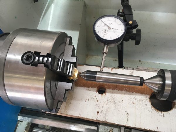
Making great progress. I loved that little trick with the dead center, very clever. Little tricks like that are gold to us amateurs who don’t have the luxury of a curmudgeonly master machinist looking over our shoulder.
If the hole doesn’t have to be perfectly positioned, another way to do that is to simply “pin” the part against the chuck (on parallels) with a live center, then tighten the jaws carefully against it. Tightening the jaws will shift it a bit, so it won’t be perfect, but a lot of times this is close enough and saves setting up the indicator and such. That likely would have been fine here as well, but working precisely is always nice when time isn’t critical.
Definitely interested in the tailstock die holder discussion.
I have the same boring bar (okay, the same _model_ of boring bar) and, yes, it’s lovely. All the old brazed carbide ones are slowly vanishing from the work area into the sargasso sea at the back of one of the lathe drawers.
Yah, this one has high-speed-steel inserts, which work really great in my small lathe. They’re probably expensive to replace, but some jobs they are just the ticket.
Oh dear, brass boiler fittings are not good … please have a read up on dezincification. You might want to re-make those fittings in bronze before you solder them to the boiler otherwise they are a ticking failure point in your boiler.
The project I’m following from Live Steam magazine specifies brass for all fittings, so I suspect the world may yet survive this catastrophe.