Gathering steam for the coming work.
Last time we made a bunch of straightforward plumbing fittings. We have more fittings to make, however, and we’re getting to some very interesting ones. Next up is the steam dome. What’s a “steam dome”, you may ask? Well, ever wondered what those bumps are on the tops of steam locomotives? At least one of them will be a steam dome. There may also be a sand dome, and some domes are just covers over equipment, but a steam dome there will be.

Boilers make steam by boiling water- every schoolchild knows that. However, steam comes in many different grades. Broadly, steam is divided into “wet” and “dry”. This is basically a measure of how much water vapor is suspended in the steam. Steam engines need to run on dry steam, because suspended water droplets would collect in cylinders and valve gear, gumming up the works. Since water isn’t compressible, this can in fact be fatal to pistons and rods. Too much water in the cylinders leads to hydrolock, which is a very efficient way to destroy piston connecting rods.
Dry steam is also generally invisible (or very hard to see) because the water droplets in wet steam are what you can actually see. This makes live steam (aka dry steam) very dangerous. It’s much hotter than wet steam and very hard to see. Industrial steam cleaners, for example, produce live steam, and are a super good way to have a real bad day.
The purpose of the steam dome is to isolate the desirable dry steam. At its most basic, it’s just a high spot in the boiler. The dry steam rises (because it’s the hottest) and collects at the highest point. The steam dome takes advantage of this to concentrate the dry steam and funnel it to the engine. This is passive steam separation, but there are active methods as well. There are centrifugal steam separators, for example, that leverage the mass difference between wet and dry steam. Our steam dome is a very simple one, consisting only of a high spot in the boiler, and some small holes to help prevent water from splashing up in there.
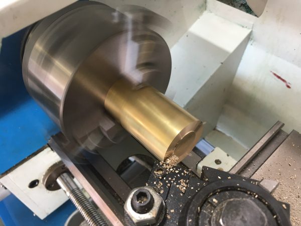
The steam dome is an interesting part to make on the lathe. It starts with a large piece of brass stock, turned to 1.5 inches.
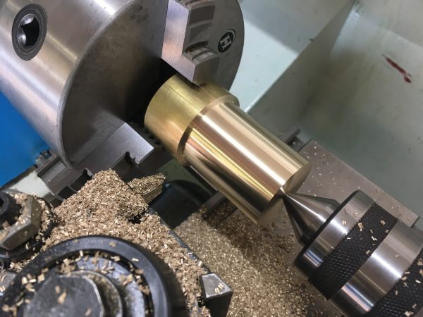
The top of the dome has a very generous filet on it, which gives it a dome-y sort of look. This is primarily decorative, I think, since a blocky cylinder would feel unfinished. There are a couple of ways to create this. Brass turns fairly easily, so it is possible to shape it with a hand-held tool, similar to wood turning. I’m not personally a fan of this, since it doesn’t feel very safe to me. Another approach is make a form tool.
Form tools for brass are easy to make, because the ideal top rake angle for toolbits on brass is zero. This means we only need to make a profile in one plane, with a bit of side rake. For curves, an easy way to do this is Dremel sanding drums. They come in a lot of diameters, so I simply choose one that is the exact diameter I need. By grinding away one corner of the tool bit, with the drum held at a slight angle, we get a perfect form tool with side-rake in one operation.
Form tools are not used very often on metal lathes because the tool pressure is very high. You need tremendous rigidity to keep them from chattering and making a mess of the part. There’s a reason lathes are primarily single-point cutting tools- to minimize tool pressure. Form tools go against that, and on a small lathe like this you can’t get away with much in this area. Brass is easy enough, though.
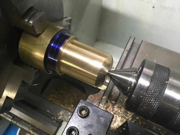
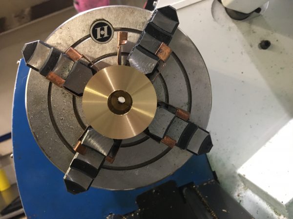
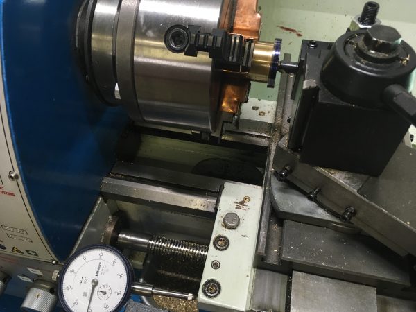
With the outer shape achieved, it was time to make this into a dome (instead of… a stump?). I parted off the piece and flipped it around. To keep our concentricity with our existing turned areas, I used the four-jaw chuck and dialed it in with the piece flipped.
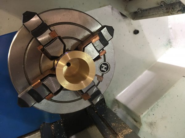
Next it was on to one of my favorite lathe activities- boring! Boring bars are neat things, and it’s cool to be able to make very large holes to very precise dimensions without drills.
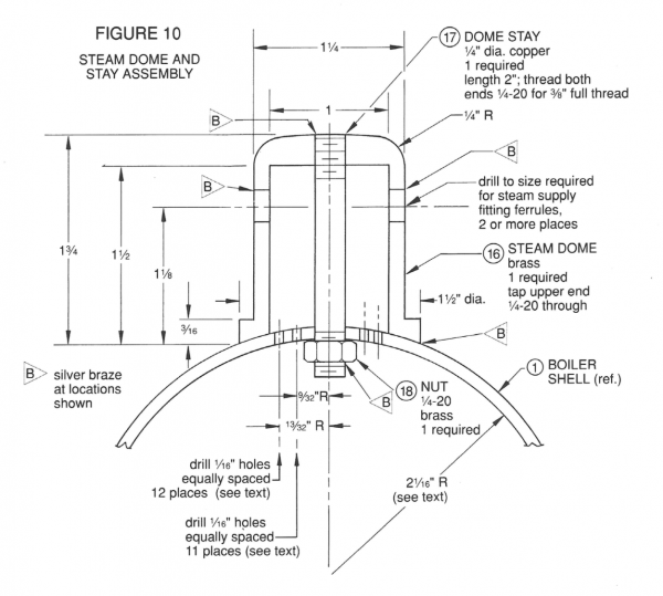
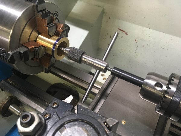
As you may recall from the drawings, there’s a stay down the middle of the boiler. This stay is made from copper. I’m not sure why, but that’s what the plans called for, and I’m trusting that Mr. Johnson knows a lot more about steam boilers than I do. This stay has a 1/4-20 thread on the end, so we need to tap the dome for it.
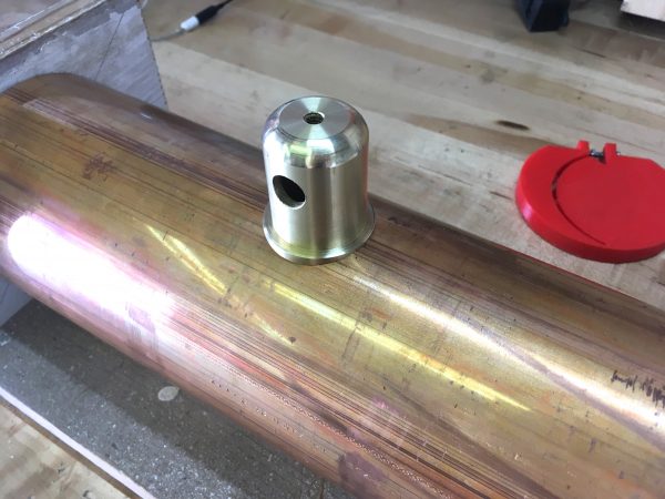
The next operation is to make holes in the sides of the dome. One hole is the steam output. This is the entire raison d’être of the boiler! The nice dry steam collected in the dome is pushed out through a valve in the side of the dome, to be delivered to the engine. Once at the engine, that steam will drive the pistons which turn the flywheels which power the looms which make you wealthy, all while efficiently oppressing your non-unionized factory labor. It’s the Victorian dream!
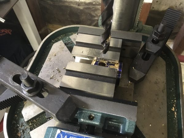
For the actual drilling, it’s over to the drill press. This operation could be done in the lathe, but the setup would been a lot of work. We don’t need ultimate precision here, because the bosses that go in these holes will be made to fit. Thus, the drill press will suffice. Nevertheless, setup was done carefully, and the part was center punched, center drilled, drilled 1/64th under, then reamed to final dimension. A cheap drill press can do reasonably precision work with careful technique.
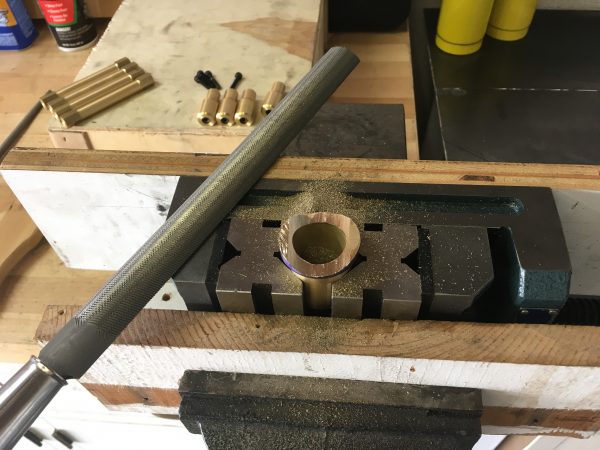
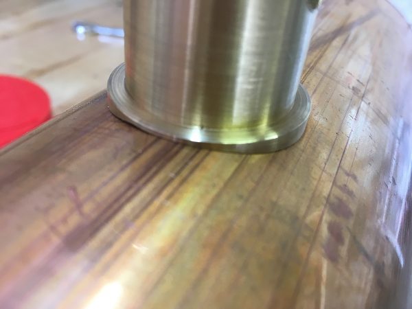
Now here comes the really interesting operation on this part. The dome needs to fit tightly against the top of the shell, which is a cylinder. Thus, we need to remove a curved section of material from the bottom of the dome of the same radius as the boiler itself. Not only that, it has to be a very good fit, because it will be brazed in place. Brazing, as we know, is not great at filling gaps. You need well-fitted parts. A milling machine would be a great way to cut this curve, but Blondihacks Labs is presently absent one of those. The part could be set up sideways on the faceplate of the lathe, at the right distance-from-center to bore the needed radius. I very nearly did this, but it was going to be an extremely complex setup, probably requiring some fixturing to be made. Instead, I decided to go low-tech: hand filing and lapping. Let’s see how that went.
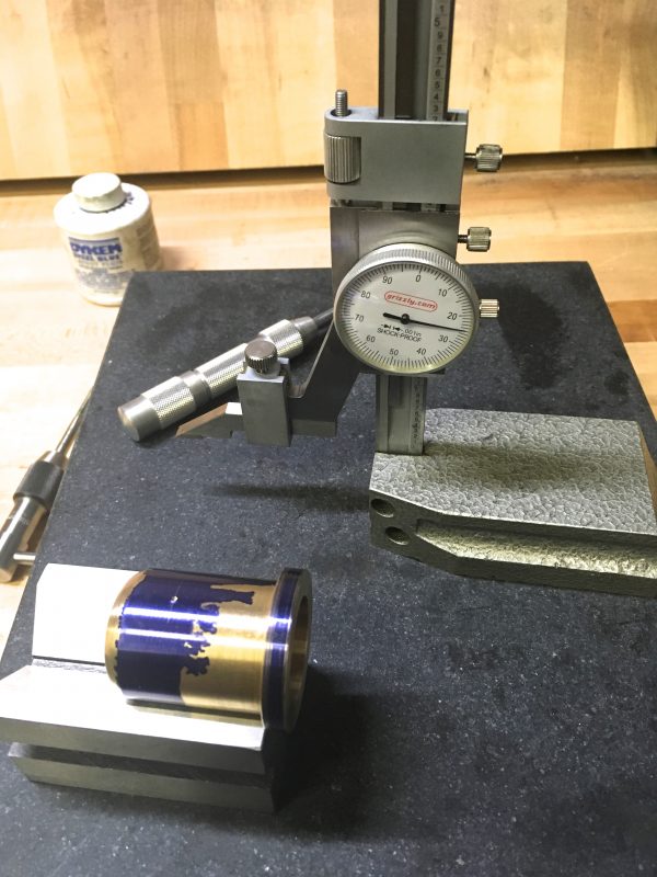
Filing a part to a specific shape takes a lot of skill, and I do not have much experience with it. I decided to practice on some scrap first to see if I could get the technique down before risking this part that I have several hours of machine work into already.
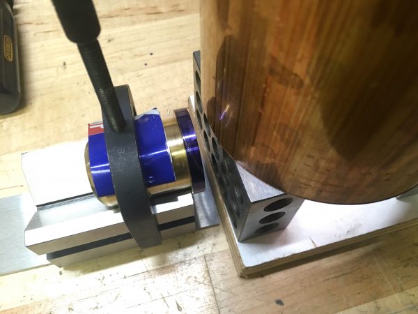
To get the final curve, I felt that lapping it in would the safest and most precise. To do that, I would need something the exact shape of the boiler shell. Well, I have the boiler shell itself! Why not use it to lap in its own steam dome? Let’s test this idea…
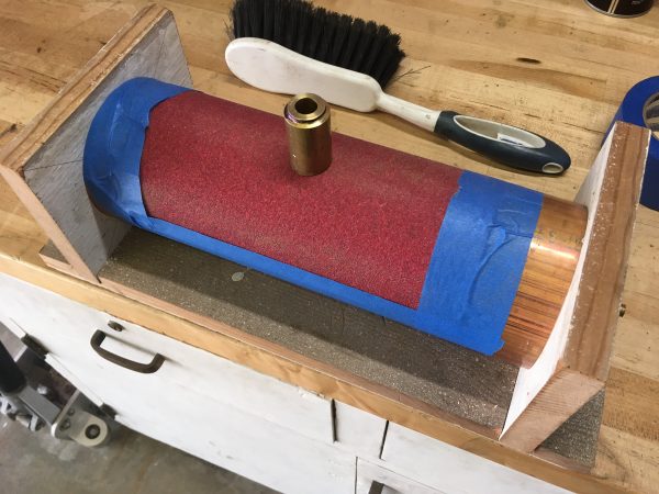
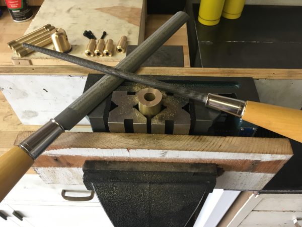
I dusted off the 3D printed mandrel that I made earlier…
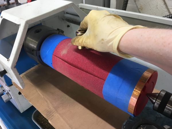
With the technique determined, I held my breath and tried it on the real thing.
I used the same lapping setup on the real dome, working it until I reached the layout line.
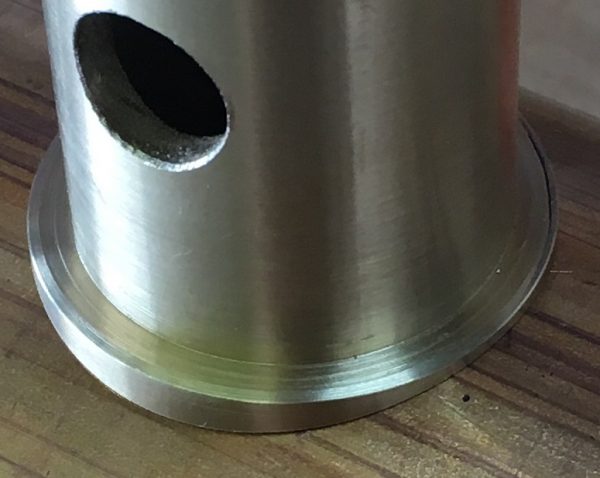
On the other side, there is a slight defect where I got carried away with the file. There’s no Control-Z in the real world, so you have to be careful.
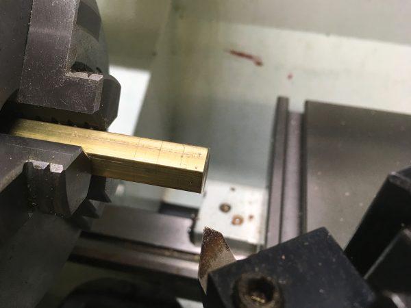
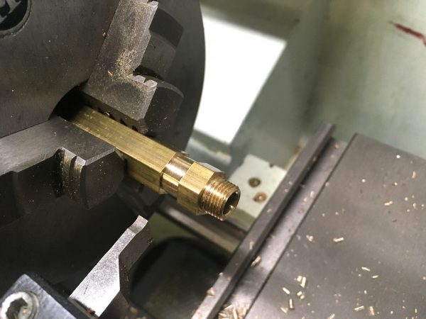
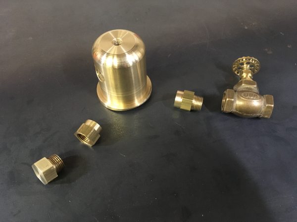
The last piece of the steam dome puzzle is the outlet valve. We need somewhere to connect that. I won’t be making the valves themselves- they were purchased from PM Research. Instead, I just need to make a boss to which I can attach the valve. I’ll also be making a 1/8″ NPT boss for the other side of the dome and plugging it. This is for future expansion, should I ever wish to draw out live steam for a secondary accessory or some other purpose (such as scalding my enemies).
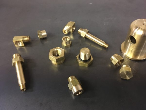
That about does it for our major fittings, and also for this post.
That’ll do it for now. Pretty soon we’ll be ready to start assembling this beast, but we have two more major parts to make before then. Stay tuned for more hot boiler action.
I haven’t done any lathe work since high school metal shop class, but I remember it being deeply satisfying to slowly carve something out of metal. Thanks for sharing your build, I look forward to seeing it all come together
“Deeply satisfying” is machining in a nutshell. There’s something about the chips coming off and leaving a perfect surface that is addictive!
I very much enjoy your writing and your projects, as always. Thank you.
Thank you for reading! 🙂
Hi Quinn, The reason why the stay is copper is because it projects into the boiler. Brass will leach out its Zinc in the boiler environment. That is why the boiler fittings are Bronze not Brass. Looks like good work you’ve done there!
The v-blocks in the vise is a great idea. I wish I’d read about this years ago. Power lapping with sandpaper looks exciting, but that came out really nicely.
This isn’t a good idea, but you can turn lovely compound curves like that dome fillet on some lathes by digging way in the back of the discarded tools pile and hauling out the lantern post, and putting a cutter in it with as little overhang as possible, then running the compound all the way back so the cutter tip is on the inside of the axis of rotation of the compound, and manually traversing the compound back and forth, akin to a ball-turning tool.
That’s a cool idea with the lantern tool post. Wouldn’t that make a spherical cutout, though? The trick with the steam dome base is that the cut-out is cylindrical in shape.
The power-lapping was surprisingly low drama, as it turns out. The lathe was running very slowly, and it was easy to control the part in my hand. I’ll definitely be using that technique again for something. It worked well and felt very safe.