Getting around to making it round.
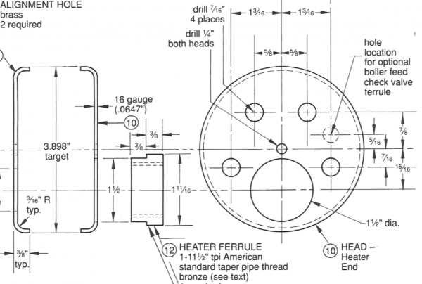
A boiler head is the “end cap” of the pressure vessel. Real steam locomotive boilers are made by rolling a large piece of stock into a tube, and sealing the seam (with rivets, welds, or other methods). The ends are then closed off by attaching round caps to form a closed cylinder. These caps are called “heads”, perhaps because one of them is at the “head” of the boiler in the locomotive as seen from the position of the engineer. The heads are generally rounded, so as to avoid a sharp corner around the end profile of the cylinder. Sharp corners concentrate pressure, and become weak points in the structure. This is the same reason the air tank on your compressor is shaped like a pill capsule.
We’re going to make our boiler heads from 16 gauge flat copper stock, which is close to the same thickness as the water pipe we used for the main body. We can’t go thicker than that for reasons that will become clear shortly.
Much like the big girl boilers, we want to achieve the rounded edges our on heads. Truth be told, since our boiler’s operating pressure is only in the neighborhood of 50psi, this is probably more aesthetic than anything. It’s safe to say this boiler is vastly overbuilt for the job it is doing.
A traditional way to made rounded caps like this would be hammer-forming. You make a form out of steel, hardwood, the skulls of small children, whatever is handy. You then hammer the copper against that form until you get the shape you want. This is fine as far as it goes, but there’s a much cooler way we can do this- roll forming on the lathe. This is an industrial process that is actually pretty easy to replicate at home, to some degree.
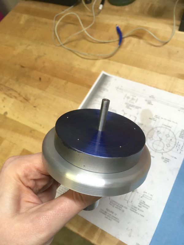
To start with, we need a pretty fancy piece of tooling. Definitely the fanciest we’ve made so far on this project. The tooling is a forming plate (similar to what you’d use for hammer-forming) attached to a mandrel that we can chuck in the lathe. The front of the form is threaded to hold a clamping plate. This holds our workpiece. We then make a roller that mounts on the tool post to do the forming. Let’s get going on the form tooling.
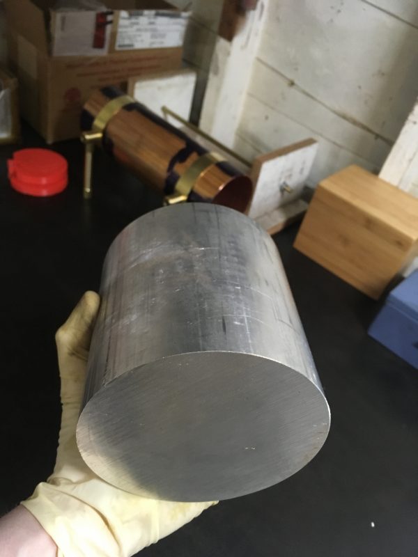
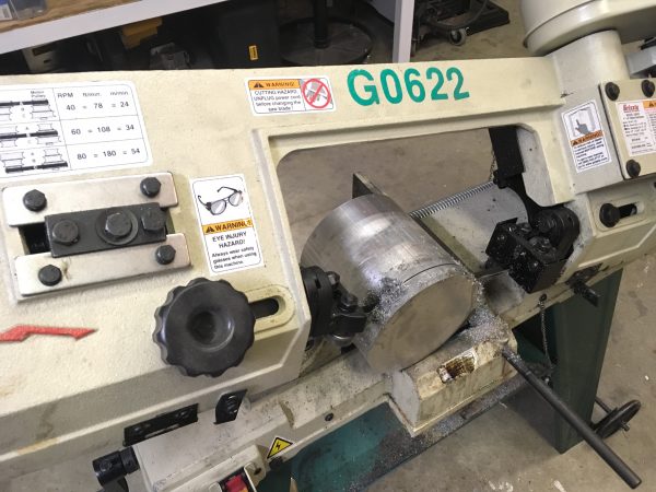
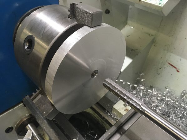
To start with, I need to cut a slice a bit larger than we’ll need. The thickness isn’t super critical here, as long as it’s deeper than the rolled heads will end up being.
With our rough piece made, we can get all precise up in here.
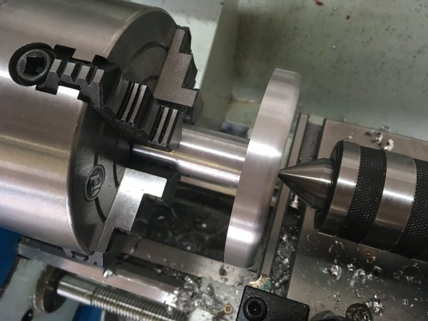
Power cross-feed was super helpful for these operations. Six inches is a lot of diameter to feed by hand on a small lathe. Power feed is also helpful in achieving a good surface finish, which is important. Any imperfections in this surface can be transferred to the copper.
An interesting aside, concentricity is not critical at this stage, because the mandrel will establish the center axis of the entire tool, and this piece will be turned to match it later on. Efficient machine shop work is all about knowing which dimensions are critical, and where in the order of operations those dimensions will be coming from.
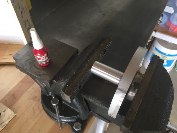
To do the actual pressing, the right tool would be an arbor press. Since I don’t have the right tool, I’m going to use the wrong one– my bench vise. This works as long as the press isn’t too demanding. We’re only one thou over here, so it’s manageable. The risk is breaking the acme-threaded lead-screw in the vise. Sooner or later that will happen if you abuse vises in this way. But not today.
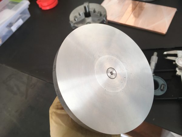
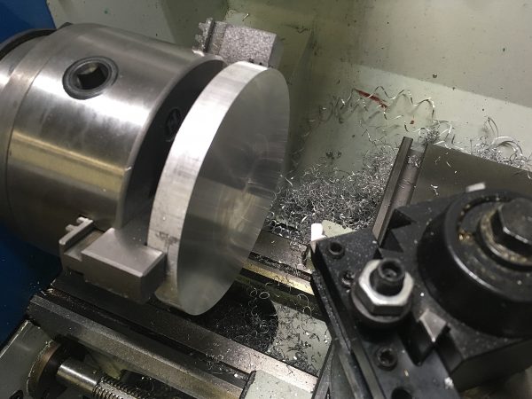
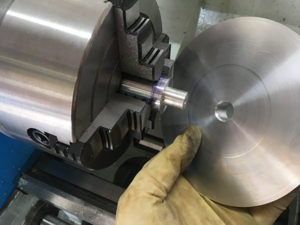
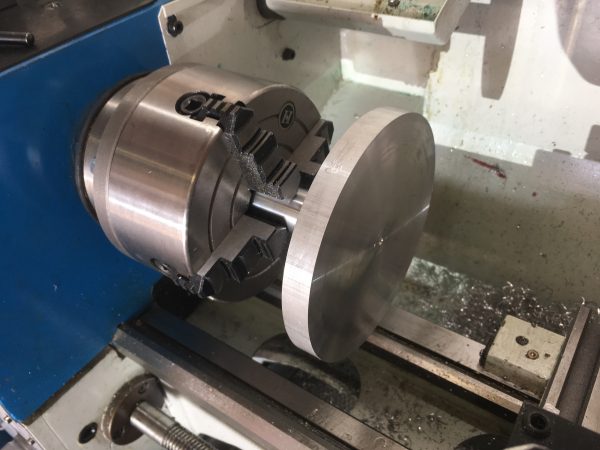
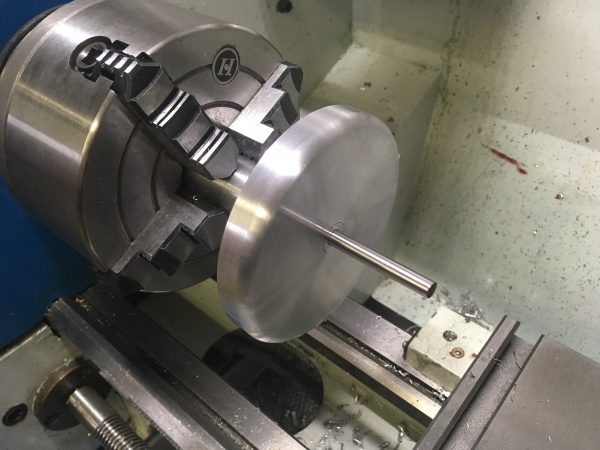
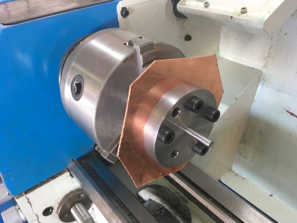
Next we need to turn down the diameter of the plate, which will also get it perfectly concentric with our mandrel. To do this, it’s time for the four-jaw chuck. As soon as the mandrel was removed from the three-jaw after turning it, concentricity was lost. The four-jaw is how we can get it back.
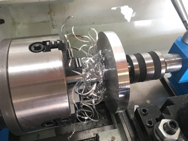
Our disk is almost two full inches larger than we need it to be, so we have a lot of chips to make. Turning aluminum is one of my least favorite things to do. It’s very difficult to get it to make decent chips. Plenty of WD-40 lubricant and pouring on the speed seems to help, but stringy rats’ nests of chips that pile up on the chuck is hard to avoid.
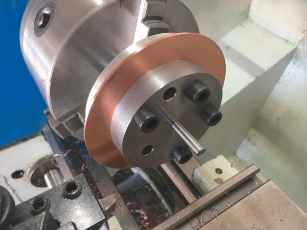
With the diameter turned down, we need to form a large fillet that will give the boiler heads the desired shape. To do that, I made a large-radius form tool.
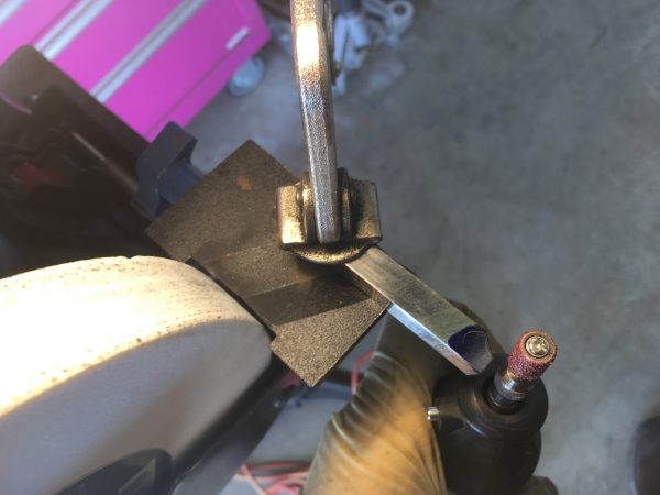
After grinding the profile with the Dremel, you can grind a top rake in the usual way, if needed. I decided to give it a try with zero top rake, which is the opposite of recommendations for aluminum. This worked surprisingly well, despite aluminum usually requiring a lot of top rake.
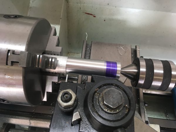
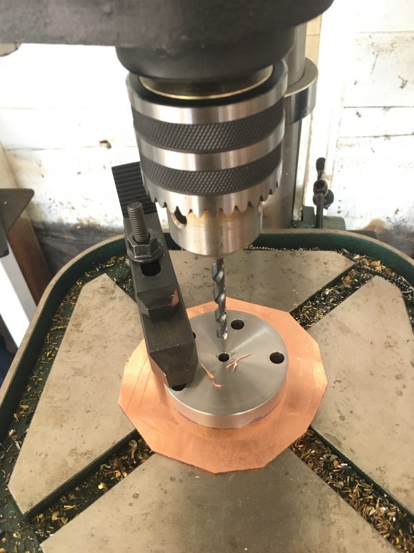
The final operation on this setup is to drill and ream the center to take a piece of drill rod. This serves as the registration pin for all the operations that will be done with this tool.
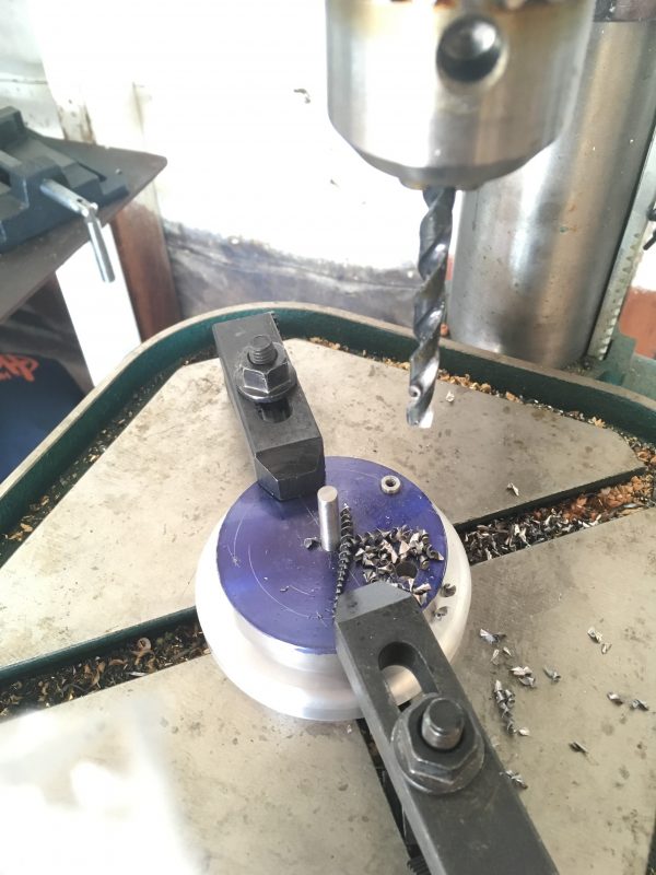
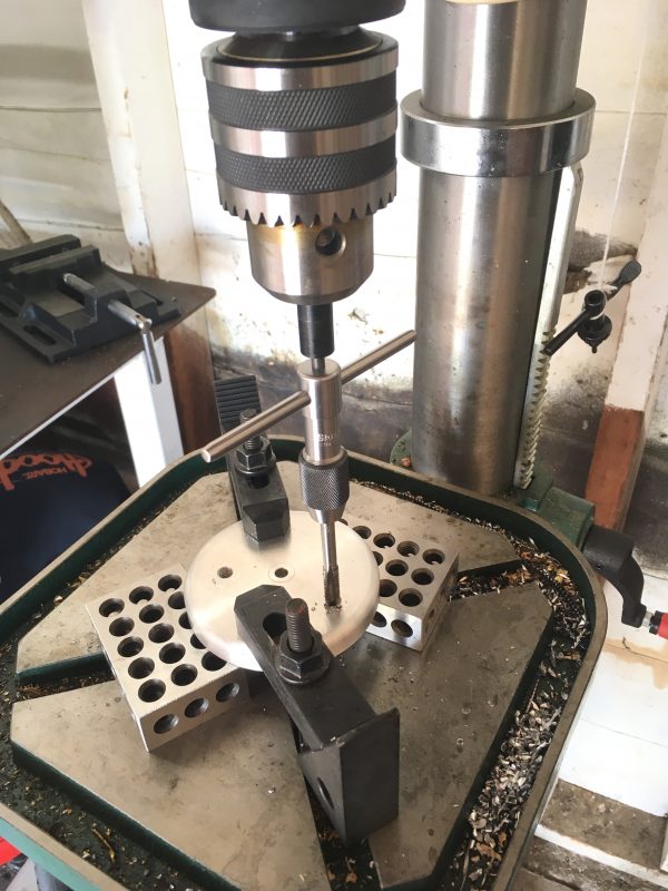
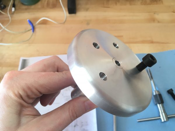
Next we need to make a clamping plate for the front face of the tool. For this I grabbed a chunk of three inch steel off the junk pile and faced both sides of it.
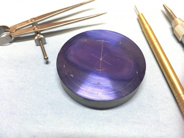
This layout was really tricky, since there are no fixed reference points and the holes are in a trapezoidal pattern. I did it all with a simple compass and a lot of math. Sometimes the old ways are still the best ways!
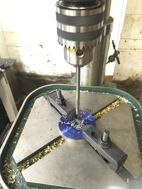
To guarantee all the mounting holes line up perfectly, I match-drilled everything (rather than trying to do that tricky layout a second time and hope for an identical result).
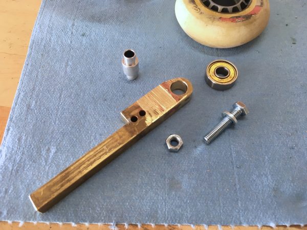
With the base tool and the clamping plate done, all we need is the roller tool. For this, the junk pile produced a chunk of brass and an old roller blade wheel. Discarded roller blades are a great source of high quality bearings. They’re typically ABEC-5, and the “tire” part of the wheel is consumable, so the bearings are usually still good in worn-out wheels.
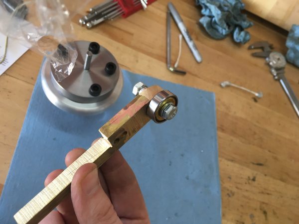
Okay, the tooling is done! Now we get to make some boiler heads!
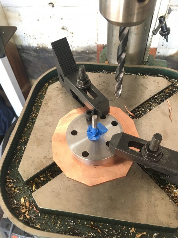
With the holes drilled, the copper is then affixed to the tool with the clamping plate.
I started by turning the copper down to the right dimension. This is a bit tricky to calculate, because you need to account for the radius of the bend that will be created. There are online calculators that can help with this.
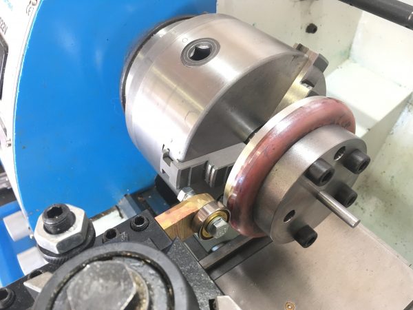
The actual forming process needs to be done slowly and carefully. A very low RPM is used, and the roller is set at just ten degrees off the face. As the roller touches the copper, the material will gently fold over against the form. It’s critical not to leave the roller touching any longer than necessary, because copper work-hardens very easily. If the copper hardens, you have to remove it and anneal it with a torch to get it soft again. This will need to happen anyway, two or three times during the process.
If you get greedy on the angle, the edge of the roller will dig in and scar up the surface, so be patient and go ten degrees at a time. Use the compound to feed the roller tool into the work, and keep the carriage and cross-slide firmly locked for rigidity.
Here’s a video of one 10 degree roll operation.
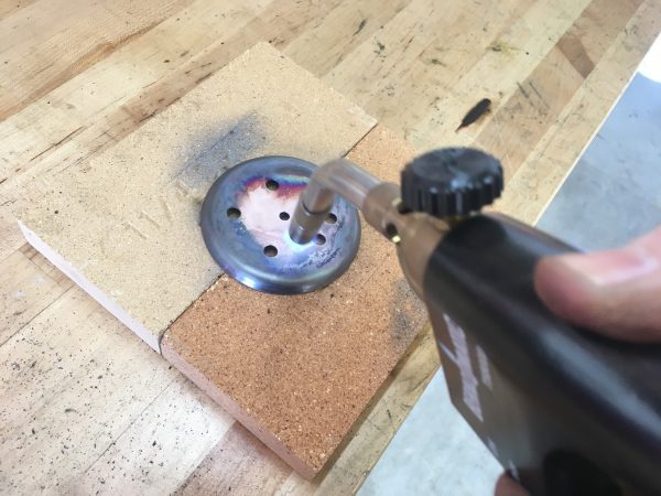
I stopped and annealed each head four or five times. Once the copper is fully seated against the curved form, we’re done.
This fixture may see further life later as a small faceplate, or I may make more heads with it. That’s all for now! Roll forming sheet metal on the lathe is easy and fun. Making the tooling is a great exercise also, and the end result is undeniably pleasing. I hope you agree!
Dear aunt Quinn,
yes, it is. The end result is undeniably pleasing!
Love,
Ziggy
That’s nice work, and it came out beautifully!
The only time I’ve had a vise fail when using it as a press, the movable jaw casting failed: cracked right through, starting at one of the points under the jaw where there are sharp edges for holding pipe below the main jaw. Boy did it make an impressive sound when it went.
This was followed by a lot of learning about all the wrong ways to repair a crack in cast iron.
For a one-time metal-spinning tool, you can also use wood. I drilled a hole in a pine 4×4 and tapped it to fit my lathe spindle, then turned the wood to the form I needed and spun aluminum over it. I also used the rollerblade bearings but used the wheel as well: found the hardest wheel I could, and used that as the tool running against the metal. It did a lovely job with no risk of scratching the work. I ended up making a scissors tool like https://i.pinimg.com/236x/51/fe/45/51fe45d93d19ed49c299510615da6d0d.jpg around the rollerblade wheel, and it did a lovely job. (Way too easy to move the metal way too fast with this much leverage.)
Wow, that’s a very impressive setup! I assumed the rollerblade wheels would be too soft, so I went straight to the bearings. Cool to see that it works with the right wheels! Does the aluminum work-harden? The copper does very quickly, so you have to run the lathe slowly and get in an out quickly with the roller.
This was 3003 aluminum, which was recommended for spinning. It doesn’t work-harden anywhere nearly as quickly as copper. I suspect 3003 may not work-harden at all, because it’s close enough to pure. (I was learning and figured I’d try for the easiest thing I could.)
Note the setup pictured isn’t mine. Mine looks like someone welded it up out of EMT and bits of junk found lying around the workshop, because, well.
I’ve seen people do useful spinning with a 25mm oak dowel rounded off on the end and polished, which is what led me to try the rollerblade wheel. Other people seem to use nylon or hockey pucks turned to fit bearings, which would certainly be harder.
Regarding the vises, I have seen other YouTubers snap castings also, so maybe this is universally the weak point on vises. I’ve been assuming the leadscrew is the weak point, but I’ve never actually pushed a vise to failure, so it sounds like I may be quite wrong about that.