Empowering the heads to do their jobs
Last time we roll-formed some copper stock to form the heads, and that was pretty cool. We have a few more operations to do on those pieces, and we need to make all the head-related accessory parts for our boiler.
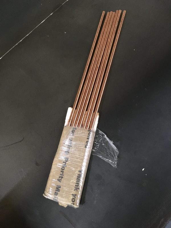
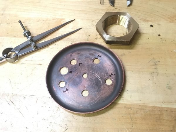
First up are the stays. A “stay” a very steam-engineer word that usually means “a rod that keeps something else from exploding”. In this case, the something else is our heads. Thus these are “head stays”. The main body of the boiler is a cylinder, which is an inherently strong structure. Circles are really good at containing pressure. However, the heads are flat at the ends. They are a theoretical weak point in the structure. As I’ve stated before, I think Mr. Johnson’s boiler design is rather overkill for the 50 psi working pressure it will see, but I also acknowledge that no part of me is a mechanical engineer and I know basically nothing about pressure vessel design. I’m taking his word that these head stays are necessary. The head stays take the form of four copper bars that run the length of the interior, threaded into brass bosses in each head. This ties the heads together and also ensures the pressure isn’t being contained solely by the braze joints on the heads.
As I’ve mentioned before, eBay is my go-to for metal stock in small amounts these days. Thanks to flat-rate USPS shipping boxes, most sellers offer free shipping, even on rather substantial chunks of steel and iron. The other day, I received a 20lb steel bar in a flat-rate envelope. Roughly 47 envelope molecules survived the journey, but the 20lb steel bar was fine because it’s a 20lb steel bar. I feel bad for everyone else’s mail in that vicinity, though.
The first task for our lovely copper stays was to thread the ends ¼-20 for the mounting ferrules. Threading copper is really difficult, however. A threading operation involves a lot of tool pressure. The die is cutting multiple threads at once, and it relies on the strength of the previously cut threads to pull the die forward as it cuts new ones. Copper is highly resistant to being cut this way, and isn’t quite strong enough to push the die forward through itself. So it’s both too tough and too weak, in the exact wrong ways. My solution to this was to turn the ends of the bars 5 thou under-size, chamfer the ends generously (to help the die start), use lots of cutting oil, and apply a lot of forward pressure on the die. Even with all that, there are decent odds the threads self-destruct partway through if the die gets hung up.
Another option would be to single-point cut these threads rather than using a die. However, these bars are very thin. Probably too thin to hold up well to the high tool pressures needed to machine copper.
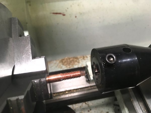
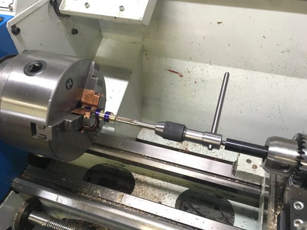
Next up are the ferrules. These are brazed into holes in the heads, and the stays are threaded in to them. We need eight of them, so it’s mass production time.
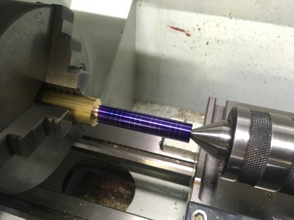
I’ve mentioned this parting-tool technique previously, but it was extra useful here. Using a wide parting tool, you can plunge into the work to the depth needed for final diameter, and make a note of the dial reading on the cross-slide. You can then cut the rest of that diameter by winding out past the backlash, then coming back in to that same dial reading on each ferrule. It’s the poor-person’s DRO.
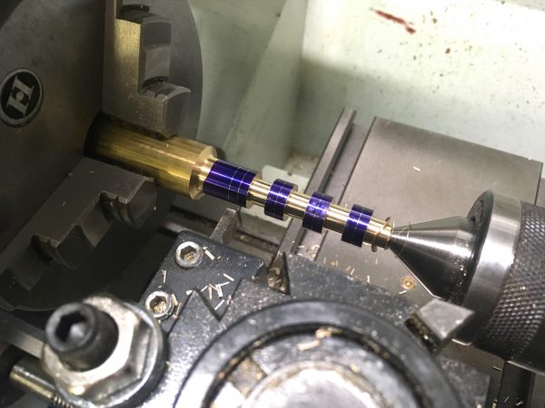
I did two batches of four. I didn’t want to do a batch of eight all at once, because the unsupported stock area in the lathe got pretty large, and the parting-tool-plunge technique requires good rigidity in the setup. This might be a good use-case for a follow-rest!
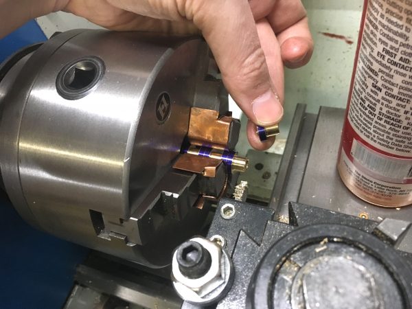
Profiled and tapped, we can now part off each one using the waste zone we marked between each ferrule.
At this point, you might be wondering about why the stays are copper, instead of brass like everything else. This is open to debate, and the original article by D.E. Johnson doesn’t say. The general belief about this sort of thing is that copper is safe for steam, and yellow brass is less-so because of dezincification. The theory goes that steam can leech zinc out of yellow brass, leaving the fitting porous and weak, and thus a potential failure point.
This is one of those things that is technically true, but irrelevant at small model scales. Yes, for a larger steam engine running north of, say, 150psi, there are regulations governing what types of materials to use in pipes and fittings. You probably shouldn’t make the whole boiler out of brass at any scale, although people do. There are some brass fittings in this design that are in contact with steam, so it could be a point of concern. However, the flip side is that using brass fittings in small low-pressure boilers is common practice, and model boilers are not murdering people by the thousands. For further antidote to any imminent concern-trolling, the design here is by a man with plenty of boiler making experience, and published in a reputable magazine all about making steam boilers. If this thing was a death trap, we’d know about it. Finally, note that dezincification mainly happens when using mineralized water in the boiler, and I’ll be running only distilled in this one (mainly to reduce scaling problems).
So, is dezincification of yellow brass in a steam environment a real problem? Technically yes. For us, no. If you’re building a big high pressure boiler, stick to bronze fittings and cast iron pipe. If you’re building a fun little one, relax and get on with your life, already.
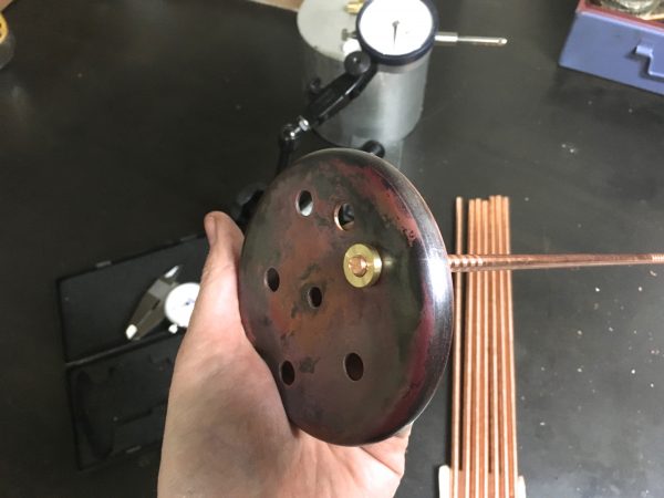
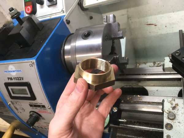
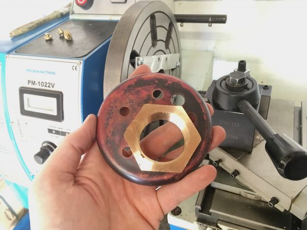
Okay, back to our heads! Each head serves an additional important purpose. One holds the electric heating element, and the other holds the thermoswitch that controls it. They are both immersion devices, and we need mounting bosses for each. I opted to buy suitable bronze pipe fittings for this, since it was easier than trying to make them. The heating element in particular uses a very large NPT thread which I didn’t want to attempt to make myself.
For the heating element, I bought an adapter fitting from one pipe thread type to another. The “other” didn’t matter, but the inner thread matches my heating element. Bronze is pretty expensive, so buying a commercial casting like this saves a lot of material and thus hard-earned Patreon farthings.
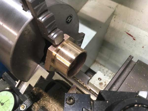
The poor quality of this fitting would come back to haunt me later, though. I had difficulty getting these threads to seal. More on that in a later article. Anyways, I repeated this process with a much smaller bronze casting for the thermoswitch.
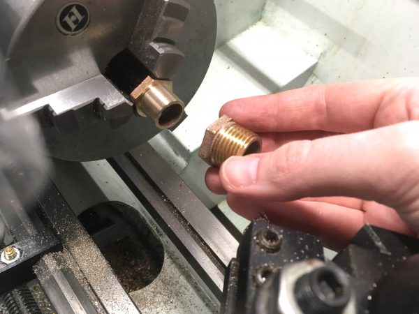
Note that all of the small head fittings were turned to a couple thousandths over size for the holes in the heads. I then used a tapered hand reamer to open up each hole slowly until the ferrule/boss/etc was a very close fit. This should help make brazing cleaner and easier later.
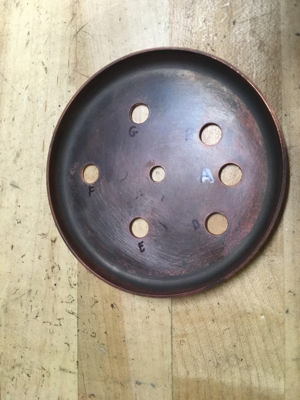
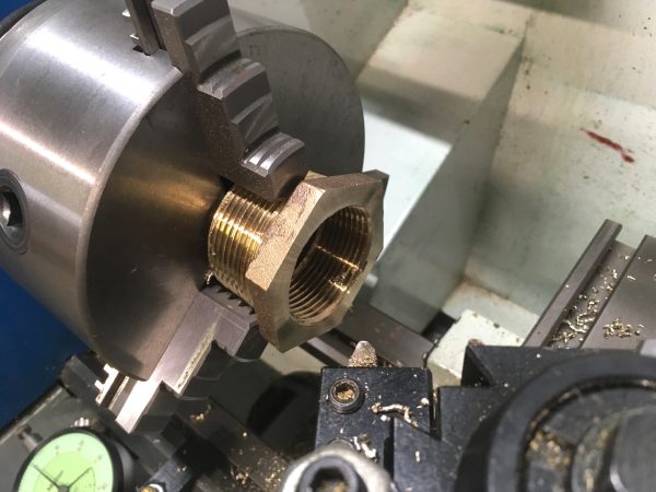
With the two large bosses made, it was time to make holes in the heads for them. The heater element boss is particularly interesting, because it’s much larger than any drill bit I have. This would be a good operation for a boring head in a milling machine, but I also possess neither of those. When all you have is a hammer, you view every problem like a nail. When all you have is a lathe, everything starts to look like a faceplate operation. You’ll see what I mean shortly.
The only way I have to make a large hole is the boring bar on the lathe, so we needed a setup for that. Not really planning ahead at this point, I started with the four-jaw chuck. First we need to make a hole big enough for the boring bar to get started.
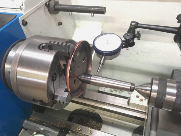
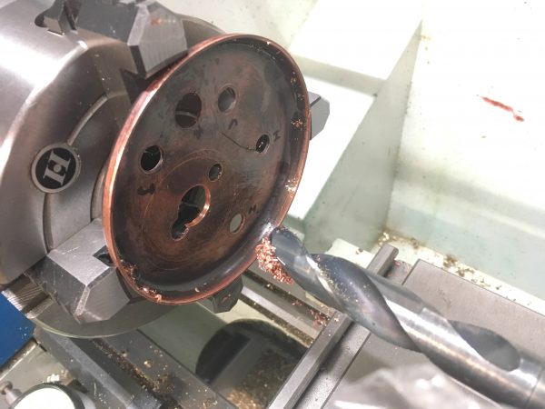
Now we’re ready for the boring bar. It was at this point that I realized I couldn’t go any further with this setup. There wasn’t room to clear the jaws with the boring bar– the hole was too big. There also wasn’t room to get sacrificial material between the workpiece and the jaws, so it was time for the faceplate.
The setup I came up with involves sacrificial aluminum strips threaded to accept short mounting screws. The strips are mounted to the faceplate with hardware smaller than the faceplate slots, which allows me to adjust the piece to get it centered.
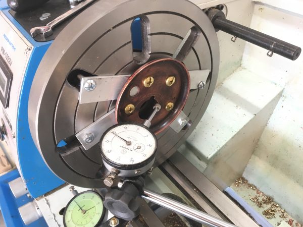
This setup was very time consuming, as I had to gently tap the piece around until it was dialed in. I didn’t have the luxury of any jaws to adjust, and the directions of motion available here are not orthogonal. All the mounting plates are at weird angles, so I had to learn how tapping each one affected the run out, then use that knowledge to dial it in. It was tedious, but I only had to do it once! This would have been immensely easier if I had started with the faceplate, since I wouldn’t be trying to indicate in an existing hole (with a gap in it, no less). However, it goes to show that with some sweat and ingenuity (in that order), you can recover almost any situation in the machine shop.
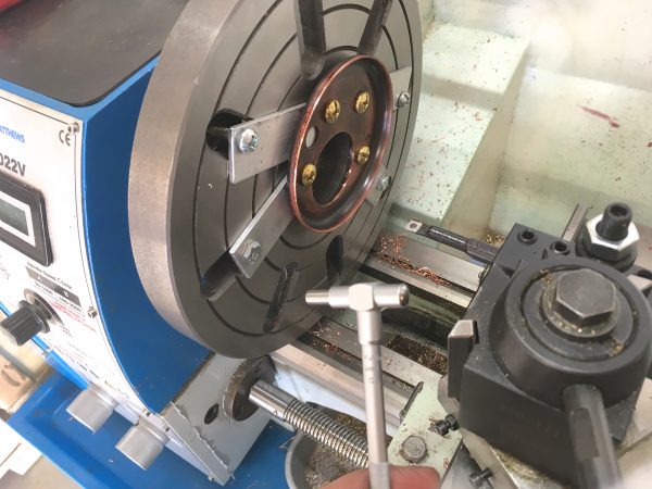
I used the telescoping gage to get the diameter half a thousandth larger than the boss I had turned from the crappy casting. Just enough for a snug slip fit.
With that, our heads are ready for assembly! We’re getting perilously close to being able to assemble this boiler now. We’ll be making steam (maybe) before you know it, so stay tuned!
One last thing- Blondihacks is now on Instagram! Follow me there for sneak peak photos of upcoming projects. You can find that link (as well as Twitter) any time at the top of the site.
Project is looking good, lots of interesting processes. Almost sorry I started following you on Instagram, I liked following along with you narrative on the website as you’ve progressed. How do you like the lathe so far? I’m curious how you feel about how suitable it is for the scale of the parts you’ve been working on, especially the small fittings. Any issues with using a lathe that size for small parts?
I honestly have debated that internally for a long time- does it “ruin” the blog posts for people if I post current photos? The blog is generally a couple of months behind, since it takes time to edit photos, gather research, and produce these articles. However I also want to have interesting things to share on social media with readers. I’m hoping a good balance is this opt-in approach. If you don’t want spoilers, don’t follow me on Twitter or Instagram. If you don’t mind the spoilers and/or want more behind-the-scenes stuff, go ahead and follow me. I’m open to peoples’ thoughts on this. I’m honestly not sure what the right answer is here.
Regarding my lathe, that’s a great question. These parts are all a good size for this machine, I think. My PM-1022 is at the high end of model-making, or the low-end of machinery building, depending on your perspective. I like it because it’s small enough to make clock and model steam engine parts, but large enough to make the occasional car part or other real-world thing. It’s definitely too big for watch parts, jewelry, that sort of thing. I mean, I could make parts that small, but it’d be a struggle and the results may not be great.
Machinists like to say “you can make small parts on a big lathe, but you can’t make big parts on a small lathe, so get the biggest machine you can”. I think that’s only sorta true. There’s a practical lower limit on the parts you’d want to make on a given machine, even if it’s technically possible.
On the specification of copper rather than brass for the stays – my suspicion is it’s to do with thermal expansion coefficients (brass 18-19 um/K depending on composition, copper 16-17 um/K). Obviously you want similar coefficients for everything in the boiler, but it seems crucial to me that the stays should be slightly less prone to expansion under temperature than the shell, in order to put the whole thing into slight compression, and avoid the possibility of putting braze joints into tension. But, I’m not a boiler designer either!
Yes, that’s a very good point! The rods would have the opposite of the desired effect if they expanded faster than the shell. You’re probably right about the reasoning!
I just look at that huge hole you put in the end cap and I just wonder if there was a better way to do this, or a better way to orient the boilder. Maybe vertically with the boiler being shorter and wider?
Also, will you be brazing the ferules into the end caps to seal them? How about the threads, since it looks like the rods will go through all the way. Or will you just accept some leakage, since they all seem to leak no matter what.
And I wonder if just using a single center rod on the inside, and then four rods on the outside to a pair of rings which go outside the boiler and the end caps. Braze the endcaps to the boiler, and then braze the support rings to the rest of it. Very much like compression straps on a stuff sack for a sleeping bag.
I can see how getting a true dome for the end caps would be a horribly painful thing to do, either you’d have to spin form them or buy them. Dunno… happy to just see how this all goes!
Well, the big hole has to go somewhere, and the heads are flat so it’s a lot easier there. If you do it on the cylinder, you have a big sealing challenge. Also, the heating element is 7″ long, so you need room for that. The dimensions of the boiler are set by the sizes that copper pipe comes in, so we have to work with that.The ferrules are brazed into the end caps, for sure. They have to be or they’d never seal. Similarly, the threads are brazed into the ferrules. So the process goes- braze ferrules to one head, screw in rods, braze threads, pass rods through other head, screw on ferrules, braze ferrules to head and threads on other end.Your ring idea is certainly interesting- anything that makes fewer holes in the boiler is nice. It might work!
In my many years I have done a few uncommon things, and picker up trivial knowledge as a result. “Stay” is also the name of the whale-bone/bovine rib/bamboo/wood/rubber coated sheet metal stiffeners in a corset or girdle.
I suspect the origin of the words are identical, but keeps other things from exploding works.
Interesting! I’ve heard the term “boning” for corset ribs, since they were originally whale bone.
A stay is also a particular set of ropes on a sailing vessel- I believe specifically the ones that secure the sails, if I remember from my sail training days. These fit my definition, since they keep the wind from ripping the sails off and thus “exploding” the ship. 😉