The heat is on.
After months of making parts, we’ve finally reached the point where we can start assembling this boiler. Now we have some brazing to do. A lot of brazing.
This process is also sometimes called “silver soldering” because the process very much resembles soldering, except the solder has a very high melting point. Silver solder has a fair amount of actual silver in it, which is the secret to its strength (and price tag). This is not to be confused with plumbing soldering, which is a much lower temperature process. That’s sometimes called “soft soldering”, but not to be confused with electronics-type soldering which is a different thing once again. This stuff can be tricky to self-teach because there are a whole family of vaguely-related processes that all have a variety of names (that also vary by country). Googling it is difficult because you may not know exactly which process you’re reading about. I’m choosing to call this “brazing” here because I think that more accurately reflects the scale of the process. It’s more similar to, say, repairing a crack in cast iron with a bronze welding rod than it is to soldering a circuit board.
Anyway, I was pretty nervous about this portion of the job, because I’m not a very experienced brazer. I’ve only done it a few times, and only at small scales. This is jumping way into the deep end of the learning curve for brazing. The boiler is a large work piece, and all the joints have to be perfect or it won’t hold pressure. I swear this seemed like a good idea at the time, but we’re about to embark on the most painful project road I’ve been on since Veronica’s graphics board.
To start with, I decided to install the small fittings in the shell. We have ferrules for a blow-down valve, water gauge, fill plug, and safety valve. Then there are some elaborate holes for the steam dome. Before I can install anything, I need to make the holes in the shell. After months of it sitting on the bench, I’m finally going to do something to this shell!
The layout for these holes was actually pretty challenging, and truth be told I didn’t do it very well. The trick is getting two centerlines down the axis of the boiler, exactly 180º apart. It doesn’t matter where on the shell they are, it only matters that they be precisely opposite. This matters more than you think, because it governs the angle at which the fittings stick out of the boiler. Not only does it look weird if the fittings are crooked, but for the water gauge, the attachment points need to be parallel above and below the shell. This will haunt me later.
I did the layout very similar to how it was done for the legs. I applied layout dye to the relevant areas, then used a height gage and some creative piles of precision blocks on the surface plate to line things up.
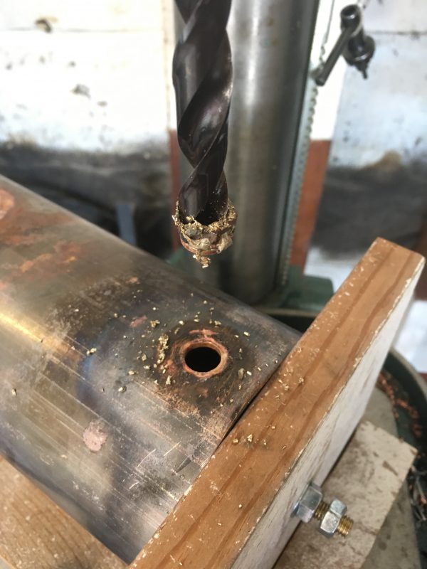
The first hole I drilled was for the blowdown valve. I started on the bottom, because it’s less visible. If there’s any step in this process that needs practice, I want to do it there.
The rest of the ferrules followed this same process, so I won’t show them all here. Two other accessories were more interesting, though- the fill plug and the steam dome.
When I planned the fill plug, I wanted it to be comfortably large, because you need to pour water into that opening. However, if you make it too big, it’s difficult to install because you end up with a large flat area being attached to a cylinder. The seam gets larger the larger the flat thing is (and the smaller your cylinder radius is). That’s why the steam dome had to be carefully fitted.
The next unexpected problem is that the fill plug is too large for my tapered reamer trick to work. A larger tapered reamer is very expensive, so I opted to open up the hole with a circular file instead. This worked, but the fit is not as good as the other fittings, and that would come back to haunt me big time later. Noticing a theme here? A lot of things I did at this stage made later parts of this a whole lot harder. Learn from my mistakes.
After all the basic holes were done, it was time for the steam dome. This area consists of one large hole in center for the dome stay, and two rings of small holes which form a primitive steam separator. The dome stay, you may recall, is there to reinforce the braze joint of the dome on the boiler, since the joint is in tension. Silver solder is strong in shear mainly, so the stay is good insurance. The little holes form a sort of screen to keep water out of the dome and hopefully collect mostly dry steam.
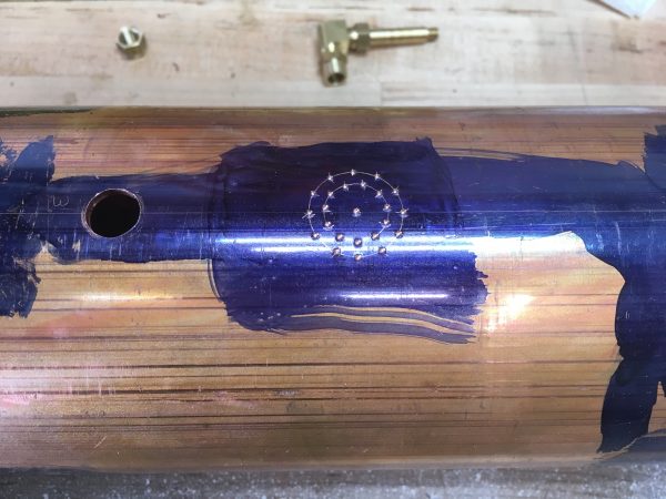
Most online bolt-circle calculators are designed for DROs on mills, so they give you a series of X/Y coordinates for each hole. This is completely useless for doing layout by hand. If you search around, you can find calculators that give you the chord length between holes. This allows you to set a compass and walk your way around from one hole to the next. I like this one (PDF). That’s a nice one-pager you can hang on the wall.
At this point, all the fittings are made, and the holes are drilled. It’s time to start brazing! Since I’m still pretty new at this, I opted to do some practice on scrap first.
For a heat source, you have a lot of options when it comes to brazing. Some jobs can be done with a plain propane torch, like you might use for plumbing soldering. Really small jobs, such as jewelry, can be done with a chef’s torch. Larger jobs are better suited to something like Map/Pro, which burns quite a bit hotter than propane. These are the yellow bottles at the hardware store. People often call these MAPP gas, but that’s not technically correct. MAPP gas was a sort of acetylene byproduct that existed because one of the companies making industrial gasses found a niche for this waste product. It was fantastic, but it stopped being produced in 2010. Industry found a use for it, so the company that made MAPP no longer sells it in little yellow bottles in the hardware store. The Map/Pro gas you now get is propane with some additives in it to burn a bit hotter. It’s still better than propane, but not the beast it used to be.
Of course, when you need the true unholy fires of hell, there’s only one choice- oxyacetylene. More on that in a moment. There’s another interesting budget alternative- propane/oxygen torches (sometimes called oxypropane). Propane is a lot cheaper than acetylene, and still burns hot enough for most jobs when fed oxygen through a gas-mixing torch. That said, oxyacetylene is not all that expensive, and still the king for big jobs.
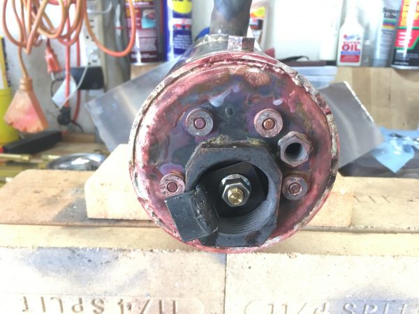
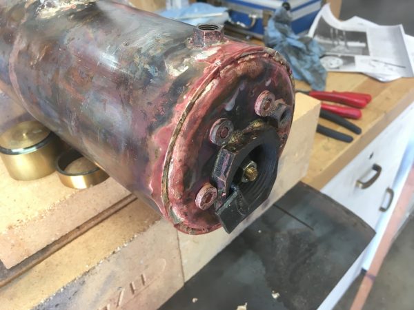
I decided to start by assembling one of the heads. All the stays, ferrules, and fittings can be brazed into one side, and the Map/Pro torch worked okay for this job. It takes some time to get the heat in and it makes a lot of soot, so everything is black when you’re done. Map/Pro is pretty hot, but it doesn’t burn clean because there’s only ambient oxygen for it to use. The flame is “running rich”, to borrow an automotive term.
For each braze joint, I thoroughly cleaned everything, then applied generous amounts of flux.
The head was a bit of a struggle, but I got it done. The challenge was getting enough heat into things. Much like soldering, the secret to brazing is that the part has to melt the solder, not the heat source. That means you have to get the whole part hotter than the melting point of the solder, which for silver solder is quite high indeed. I got it done, but it took a while. If your heat source isn’t big enough, you can reach a local maximum where the part is bleeding heat into the air and table faster than the torch can supply it. Remember from school that temperature conducts through something faster the higher the gradient is. The hotter the part is, the faster heat bleeds out of it. That means it gets exponentially harder to raise the temperature. That’s why you need a torch that burns at thousands of degrees to braze with solder that melts at only hundreds.
This should have been a warning sign to me that the Map/Pro was going to let me down. I don’t know why I thought I could do something bigger, considering what a struggle the head was. Sometimes you get fixated on a plan and it blinds you to the problems.
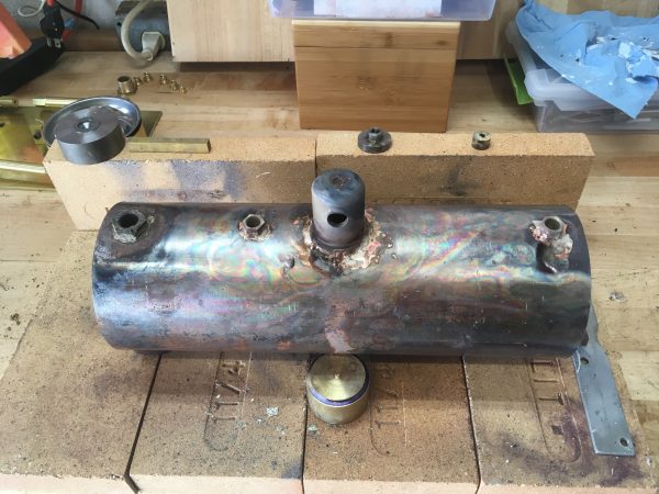
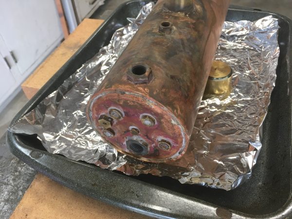
I moved on to the fittings in the boiler shell next. When brazing a large piece, you need to preheat the whole mass, to prevent that large temperature gradient I mentioned. If the whole piece is cold, the joint area will never get hot enough, because the heat will keep conducting away into the colder areas and you’ll be there all day. This is especially true with copper, which is an incredible conductor of heat.
Knowing this, I started preheating the boiler and waiting for it to get hot enough that I could get the joint areas up to brazing temperature. And I waited. And waited. And waited. After half a tank of Map/Pro, I didn’t seem to be getting there.
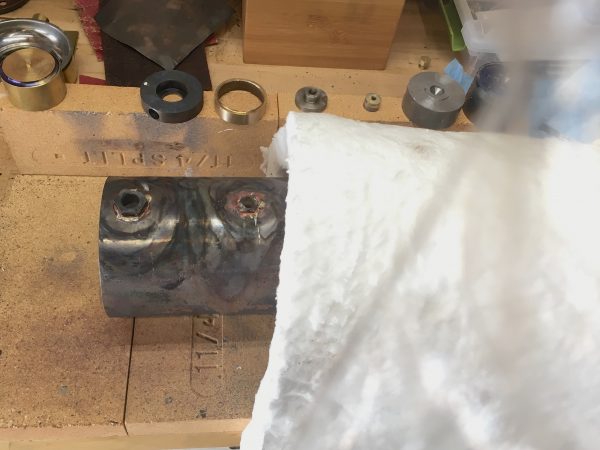
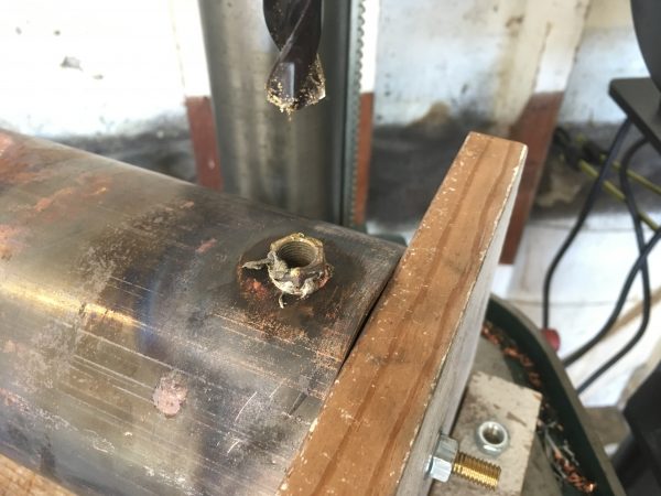
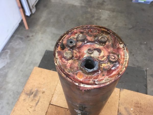
What I ended up with from this attempt was a messy couple of joints that weren’t properly bonded at all. They were so bad as to be unsalvageable, so it was with great regret that I had to drill them out and make new parts.
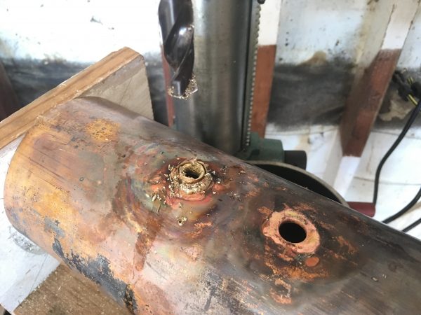
Each of these failed attempts was expensive time-wise. Not only did I have to drill out the fittings and machine new ones, but the whole area of the boiler had to be cleaned up again. Braze joints must be spotlessly clean! This meant a lot of scrubbing, sanding, scraping, and muttering of words that my mother did not teach me.
At this point, I couldn’t deny reality any more. It was time for the Big Big Fire.
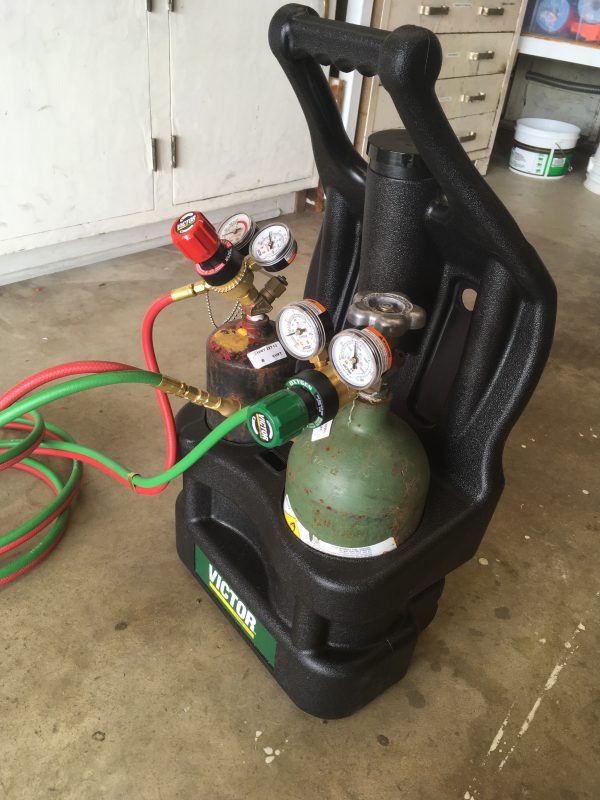
Oxygen and acetylene tanks are one of the few things you can’t buy online (due to shipping regulations) so you’ll need to go make friends with a local welding gas supplier. Sometimes they’re super nice, and sometimes they’re super mansplainey. Your mileage may vary, but I’m fortunate to live close to a great shop.
A few words of safety on these things is probably in order. Personally, I choose to store the tanks in an outdoor cabinet. I have had the valves on them leak in the past- these tanks are (very) recycled and sometimes (often) they get abused. Not by me, or you, or any of our friends, but someone out there is abusing everything. A cloud of acetylene in an enclosed space is a bomb, and that’s a conversation you really don’t want to have with your insurance company. More than once I have opened my outdoor cabinet to the distinct smell of acetylene in the air, despite the valve being as tightly closed as I can get it.
Oh, and… uh… be careful where you point it. The first rule of gun safety is don’t point the barrel and anything you don’t wish destroyed, and the first rule of torch safety is don’t point it in the direction of anything you don’t wish to be molten slag. Especially the hoses! Be very mindful of where your hoses are in relation to the white hot finger of god coming out of the torch.
When lighting the torch, the rule of thumb is “Fuel First On, First Off”. You light the torch on acetylene only, and when you’re done you shut the acetylene off first so the oxygen will blow out the flame and clear all gas out of the torch. This prevents the flame from flashing back up into the torch, and potentially even the hoses (which would be a pretty bad day).
The final safety thing I’ll call out is safety glasses. The killer with these torches is not ultraviolet like with welding, but rather infrared. The torch makes enough infrared energy to hurt your eyes, so wear appropriate IR safety glasses. They look like really dark sunglasses and turn the world a bit green. A pair may have come with your torch.
The rule of thumb for these small torches is to set your acetylene to 5psi and oxygen to twice that (10psi). Adjust the regulators so they read 5 and 10 respectively, with the torch valves open (the gauges read artificially high when the torch is closed) The oxygen tank valve should be opened all the way, but the acetylene tank valve should be opened three-quarters of one turn only. Then you crack the fuel valve on the torch, light it with the sparker, then crack the oxygen. Experience will give you the right ratio of the two, but you’re looking for a large blue flame with a little point of white flame at the base. You can go by sound as much as anything. It should be “hissing”, but not like a roaring jet. This is all pretty forgiving, though. If your acetylene is way too high, the flame will be dirty and leave soot on everything. If your oxygen is way too high, it’ll “blow out” the flame and die. Anything between those extremes will work fine until you gain experience with the subtleties.

Here’s the process of lighting the torch. It’s very exciting and easily the most thrilling tool in the shop.
Back to our boiler. The method I’m using here is to pre-heat the body of the shell for a while with the torch, and when there’s a good amount of heat in the shell (to keep that temperature gradient down), you can go in and heat the fitting a bit, then hit the joint directly for a couple of seconds with the white tip in the flame. You’ll remember from science class that this is the hottest part. Then get in there with the silver solder, while holding the heat on the metal, but away from the solder. Again, the key is to get the parts to melt the solder, not the torch. The solder will flash around the joint instantly, like magic, once the temperature is high enough. Always keep the torch moving. Oxyacetylene is powerful stuff, and you’re likely to melt anything you hold it on for more than a few seconds. Particularly your face. Always aim away from face.
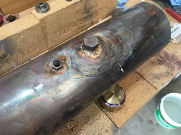
Heat control is really important in a situation like this, where the parts being brazed have a very large difference in mass. The boiler shell can suck up seemingly infinite heat, whereas the little brass fittings melt if you blink at them funny. Ask me how I know. Then ask me why I’m so good at sanding. Then ask me where I learned all those terrible, terrible words.
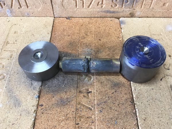
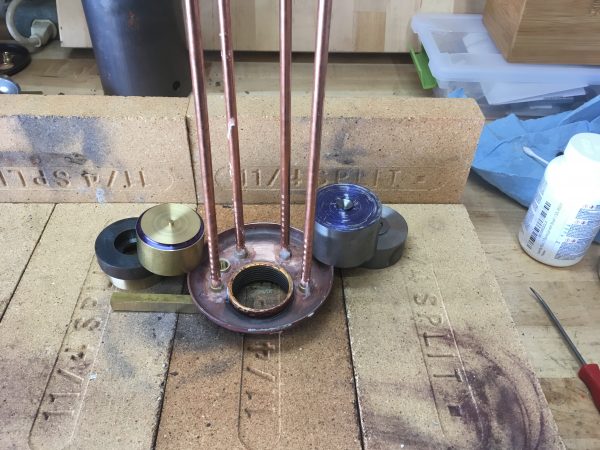
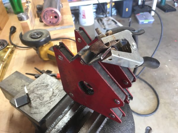
The heads are a bit tricky to hold in the correct position for brazing, so I made a strut that goes inside the boiler, and clamps to the larger openings in each head.
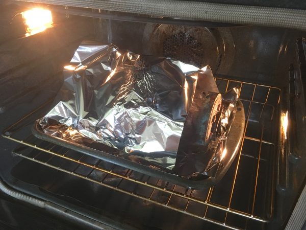
Since the heads are so massive, I felt that pre-heating the whole boiler was in order. I preheated my kitchen oven to 500°F (as high as it will go) and put the fluxed boiler/head assembly in there for 10 minutes. This worked really well and saved a lot of preheating time with the torch.
I had my brazing area all set up ahead of time so I could scoot the boiler over there immediately from the oven and get the torch on it before the preheat was lost.
Here’s some video of brazing one of the heads, to show the general technique. You can see that after flash-heating the joint itself with the hottest part of the flame, I’m holding the heat on the massive outside of the shell while applying the solder to the inside seam. The heat is all going to bleed out through the much more massive shell, so that’s where the new heat needs to go. The much less massive head will stay hot by conduction, and both parts will melt the solder.
The second head was done another day, so I had to pre-heat again.
Note that for second head, we’re also brazing all the head stays on that end at the same time. The ferrules have to be threaded on to the stays, then brazed into the holes, then the threads brazed to the ferrules. By now we’ve already brazed them at the other end, and thus nothing on that end will turn anymore.
Normally at this point, you might put the brazed parts into a pickle bath (a medium strength acid like Sparex No. 2) to clean up all the old solder crud, flux, soot, etc. Pickling solution does a very nice job of this. However, I decided to wait until after pressure testing, since I’d need to make a mess again if there were leaks to repair. This is yet another decision that would haunt me.
That’s it for the brazing! Or is it? This is the beginning of quite an odyssey, so stay tuned next time for more boiler action.
Ack, the suspense! What happened with the pickling solution? I can’t wait for the next entry – keep writing!
I’m wondering why you stopped trying to add insulation. That ceramic blanket looks pretty thin. You could get a thick batt of rockwool wall insulation from Home Depot and wrap the whole boiler with only the part being brazed being exposed. Rockwool is pretty tough stuff and it should be able to take a lot of heat. Roxul (the manufacturer) puts a propane torch to it in the promotional videos showing how fireproof it is and how it is supposed to easily survive the few thousand degrees of a blazing house fire.
It’s over an inch of ceramic insulation, which is a lot. That stuff is very efficient (and expensive). You can’t use regular household insulation for anything in the metallurgical realm. The heat is way too high and that stuff is fire-retardant, not fire-proof.
Hey, totally neato off-topic quality of Sparex #2: if you break off a tap in copper or aluminum, leave it in hot pickle for a day or two. The material will look pretty bad, but the tap will be totally gone, and the pickle doesn’t actually remove measurable material from the non-ferrous alloy.
That’s a fantastic tip, thanks! I’m sure I will use that at some point.
“the white hot finger of god”, yeh, that about sums it up, though vengeful or perhaps merciless should occur before god.
Agreed! 🙂