First three rows will get wet.
After a marathon of brazing, it’s finally time for the big moment- hydrostatic testing. A boiler’s raison d’être is to make and hold steam under pressure. This pressure is potential energy which is used to power the attached engine. The funny thing about potential energy though, is that it doesn’t always go where you want it to. When the cat pushes your favorite vase off the shelf as an act of feline spite because you stepped on her tail last week, that’s potential energy being expended in an unscheduled fashion. Expending potential energy in an unscheduled fashion for a steam boiler generally means something done blowed up, and you’re probably contemplating your life choices en route to the emergency room. We want to be sure that doesn’t happen.
People figured out long ago that the way to prevent boilers from exploding is to do a hydrostatic test on them. The boiler is filled with liquid and pressurized to two or three times its normal operating pressure, then held there for a period of time. If the boiler can hold 3x normal pressure, you can trust it to hold lower pressures and not worry about standing next to it holding your spiteful cat.
The “hydro” is what makes a hydrostatic test relatively safe. An explosion is a runaway expansion of gas, possible because a gas can expand at very very high rates when so inclined. Incompressible liquids like water and oil can’t expand suddenly like that, and thus can’t explode. If there’s a failure of the vessel under a hydrostatic test, it will spring a leak and create a high pressure stream, but it’s basicially impossible for it to cascade into a catastrophic failure of the structure and subsequent explosion. That said, if you’re doing a high pressure test, there is still danger. If you’ve ever worked around heavy machinery, as I did for much of my youth, one of the first things they teach you is to never touch a hydraulic leak. Hydraulic hoses on farm equipment and the like typically operate around 10,000 psi. While they won’t explode (because liquid), the stream formed by a pinhole leak is immensely powerful, to the point that it can go right through your hand, injecting oil into your body and ultimately killing you. This is called a “hydraulic injection injury” and it’s most commonly caused by people running their hand over hydraulic lines to check for leaks.
Luckily, our boiler only operates at around 50psi, so a hydrostatic test to 150psi will suffice. A pinhole leak at that pressure is no picnic, but this is just water, and some basic precautions will suffice. For these tests, I’m wearing a heavy leather apron and eye protection. For the highest pressure portions, I upgraded to a full face shield and threw on a welding jacket for increased shrapnel and “unplanned pressure washer” resistance.
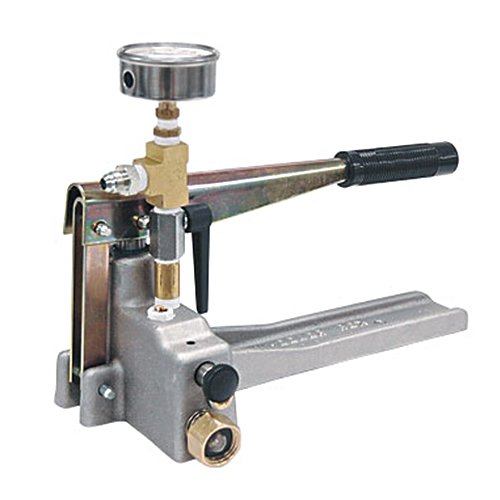
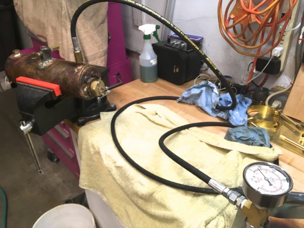
To run this test, we need a hydrostatic test pump. These can bought online in various forms and at various price points. They all work basically the same- there is a source of input liquid, and a hand pump which allows you to pressurize the fluid as it goes through. There’s a valve that allows you to close up the system and see if it holds pressure. If you don’t shut off the valve, the pressure will bleed back into your supply line, so you need a way to seal it all up and form a closed system.
The pump that I bought hooks up to a household garden hose, which is extremely convenient. I’m glad I spent a little more money for a nice pump here, because I would end up running this test many many times.
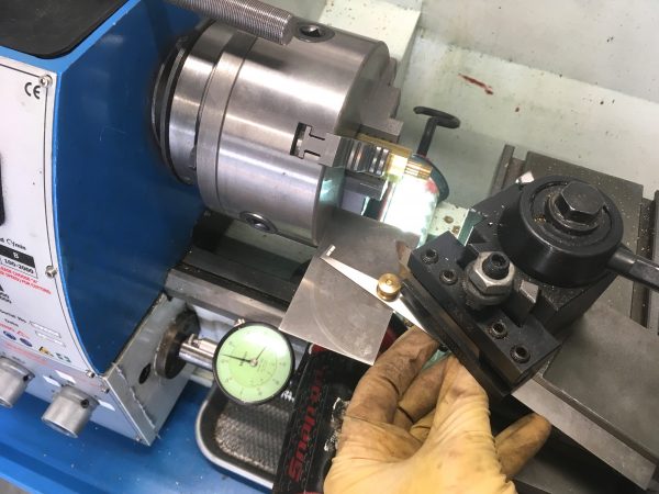
While the input is a garden hose, the output is a standard JIC hydraulic coupler (it came with the hose as well). I need a way to plumb this into my boiler, so it’s back to the trusty lathe. Any opening will do. I decided to use the ferrule for the safety valve, to save myself needing to plug that off for the tests. It’s 1/8 -NPT, so I need a very weird 1/8-NPT to 37° JIC hydraulic adapter fitting. The great thing about a lathe is that it gives one the ability to plumb anything to anything, including things one probably shouldn’t connect (such as a 600psi pump to a homemade boiler).

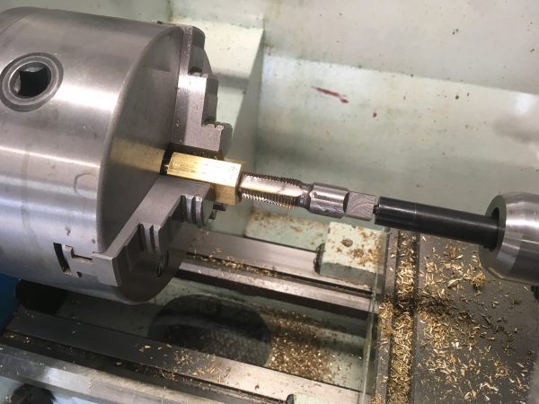
At this point my brain went on a several-hour vacation. For some reason, I decided I needed to turn the 37° flare for the hose fitting, which I really didn’t. It’s a male fitting, so it will still seat just fine at the bottom of my adapter (which has a large-to-small change in diameter halfway down). Then for some reason, I decided the flare should go on the boiler end of the fitting. Then for some reason I decided it should be a male flare, the same as the hose that ostensibly seats against it. Then for some reason I set up the lathe’s compound backwards anyway. That’s a lot of “then for some reason” moments all in one. Luckily, none of these mistakes turned out to matter one iota, save for 30 minutes or so of wasted time.
In any case, I blithely set up my lathe to turn the taper using the compound-feed method. This means setting the compound to one half the desired angle, then using it for the length-wise feed instead of the carriage. This is a super easy way to make short tapers (limited to the travel of the compound, which isn’t that much on many smaller lathes).
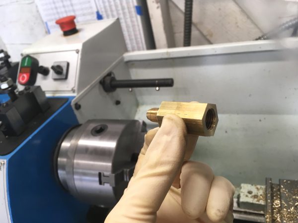
Amazingly, despite all the mistakes, this fitting gave me no trouble at all during pressure testing.
In addition to the adapter, I also needed to make a few plugs and caps for all the openings on the boiler. I wanted to eliminate variables in the first test by testing without any accessories installed. Also, some of the accessories (such as the pressure gauge) would not tolerate the 150psi test pressure. For the large openings (the thermostat and heater) I had to use the components themselves as plugs, because I didn’t have the ability to make blanks that large.

With the adapter installed, the very first thing to test is simple- does it even hold water? Given what an inexperienced brazer I am, this is by no means a given. I was actually pleasantly surprised when it did! I was so busy looking for problems that I forgot to keep an eye on the filling operation, as you can see in this video.
That video also shows the basic operation of the pump. It has a flow valve which is handy for filling the vessel and controlling the velocity of pressure buildup, and then the large pump handle is used to increase pressure above that provided by the water source.
Since the vessel appears watertight, the next step is a “low” pressure test using just the pressure from the garden hose. In other words, open the flow valve, let the hose fill the boiler, then leave the faucet on. That will hold the vessel at household water pressure, which is generally around 40-60 psi in North America.
This is the first “real” test of the boiler, and it performed…. poorly. I closed up the fill plug (it was open to evacuate air during filling), then as you can see in this video, started easing the valve open under household water pressure.
If you look closely (The water is hard to see on video), you’ll note that I tried to build a steam boiler, but have in fact built a sprinkler system or carnival water feature of some sort. I expected a leak or two, but there were more like twenty. Almost every single fitting leaked, several in multiple places. Both heads had multiple leaks on their seams. The video ends abruptly because I was so disgusted with this result that I had to walk away for a while and collect my thoughts. In my experience, this is the best way to handle frustration. Take a break, get away, and go do something else. Attack the problem when you are fresh and your head is clear.
I had a lot of leaks, that much was undeniable. There was really nothing to do but get out the torch and start fixing them. This started a cycle of:
1. Drain boiler
2. Sand, grind, drill, file, and clean area of leak as needed
3. Remove all seals, electrical elements, and plugs
4. Flux area, and preheat boiler (with oven and/or torch)
5. Silver solder area again
6. Allow to cool
7. Reinstall all seals, plugs, and electrical elements
8. Refill boiler
9. Pressurize and check for leaks
10. Repeat. And repeat. And repeat.
I went through this process literally dozens of times. Sometimes I reduced the leak count with one of these iterations, and sometimes I didn’t. Once or twice, I even created new problems. This went on for weeks. For the bigger seams, like the boiler heads, the oven preheat I mentioned last time was used, which further complicated things (but saved a lot of torch fuel and time). I won’t lie- this was a deeply, deeply demoralizing process. After a few failures in a row, I would have to take a break. A couple of times I had to stop for a week and get some space from the situation. Slowly but surely, however, I did. Make. Progress. That was what I had to keep reminding myself to keep my spirits up. Despite the constant feeling of “two steps forward, one step back”, progress was measurable. A big milestone that really helped morale was when I got the head seams sealed up and only the fittings were left. That was a big deal, because it proved that I really can do this. Those are the toughest joints to get right, so once I did, the rest felt possible. Difficult, but possible.
The boiler seams were fixable by thoroughly cleaning the joints, sanding them down, then brazing over top of the existing silver solder. For most the of fittings, I used needle files to file down the joints until the source of the pinholes were revealed, then silver soldered over them.
One tough nugget was the steam dome. After my first attempt, I had to completely redo it by filing down all the seams until I could break it loose, sand and clean the whole area, and solder it all up again. After one cycle of this, I was able to repair the remainder of the dome leaks with the file/clean/solder-over method.
Painful though it was, I learned an incredible amount in this process. Not just about silver soldering, although this was definitely an into-the-deep-end crash course in brazing. I also learned other interesting things about pressure sealing. Teflon tape is way less effective than I used to think, for example. I also learned that Loctite hydraulic thread sealant is amazing stuff. There are a lot of types of it though, so you need to do some homework. The most generally useful is Loctite 545, which has an almost superhuman ability to seal any crappy fitting against pressure. Another option is Loctite 569, which is designed (I think) for higher pressures. Since writing this, I have seen Loctite 545 make some truly dreadful fittings work properly. It’s a steam engineering miracle, that stuff.
As leaks get fixed, you gradually get to a point where more and more pressure is needed to reveal the next leak. For a long time, I had many leaks as soon as the household water pressure started to hit the boiler. I needed to get to the point where the household pressure was completely contained with no leaks before I could start using the pump to actually get to the final hydrostatic test pressure.
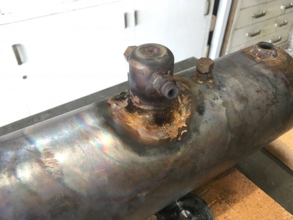
A particular trouble spot at household pressure was the large boss for the heating element. It’s a tapered thread 1.25″ in diameter, and it was made from a commercial fitting I bought on Amazon. This fitting was of very poor quality, and I could never get it to seal properly no matter how tight I made it. It got to the point where I couldn’t advance my pressure testing any further because of this. However, after I put a little Loctite 569 sealant on the threads, it never leaked again. It’s remarkable stuff. Unfortunately, I learned later that 569 is designed for small diameter threads, because of the strength of the bond. Removing this heating element (should I ever need to) will, unfortunately, be quite difficult now.
However, I now got to the point where I could start applying positive pressure with the hand pump, to work our way up to the goal of 150psi (Three times operating pressure for this boiler).
Eventually, I was able to work my way up to around 50psi, and I got down to one remaining nemesis. That damned fill plug. Remember that thing? The one where I had to open up the hole with a round file, so the fit wasn’t perfect? And the one where the fitting on was on the large side for sealing against a curved surface? Yah, that one. I mentioned how I had made dozens of passes trying to seal leaks on the boiler. On almost every one of those passes, I took a shot at fixing the fill plug. No matter what I did, the damn thing continued to leak at around 50 psi. I completely filed down the joints and redid them three times. Nothing worked.
Eventually, I went back to the source material for help. D.E. Johnson’s design in Live Steam magazine (upon which this boiler is based) had a small blurb at the end about dealing with leaks. He suggested using plumbing solder here and there as needed. Plumbing solder is not, strictly speaking, rated for high pressures. However, for a small pinhole area in an application that will never see above 60psi, it should be totally fine. It’s also an order of magnitude easier to fill a gap with plumbing solder than with silver solder. So, feeling a little dirty, I busted out the plumbing kit and starting making attempts to fix the fill plug with it. It took a couple of more iterations of filing and cleaning, but in the end the humble old plumbing solder did get it done.
For these last few repairs, I had to stop using the oven to preheat for a brazing operation, because I didn’t want to chance removing the now very installed heater. The heater would likely be damaged by the oven, so that was out. Because I used the “strong” sealant, removing it will take a pair of, shall we say, extremely non-trivial wrenches. I don’t want to risk putting stress on the braze joints for the mounting boss, so I stuck to localized heating with the oxyacetylene torch for all remaining braze operations. The boiler shell still gets very hot all over from this, but I was basically gambling on not overheating the electrical components. Luckily, they are tough and survived just fine.
Things got really exciting now. I upped my safety game a bit (adding a full face shield and leather welding jacket to the mix) and started aiming for that 150psi in the sky.
Above 50psi, interestingly, the leaks changed character. At low pressure, the leaks were like jets or sprinklers. By the time I made it to 100psi, however, the leaks were much much smaller, and they turned into slow seepages. They were like little wet areas that appear as if from nowhere. It can take some real study to figure out where the true origin of a wet spot is. It may be under the spot, or it may above it and collecting where you see it. Adding brightly colored dye to the water can help with this. This is important, because you don’t want to waste time filing, cleaning, fluxing, and resoldering an area that isn’t where the defect actually is.
Around 100psi, a new seepage appeared in a tricky area where I had filed down the side of the heating element boss to make room for one of the head stays. There was a very tight space between them that I never got a good dose of solder into. I ended up kind of smothering the whole area between the two fittings, and hoping I got it. I mostly did.
When I hit 150psi and the boiler was still dry as a bone, this was an incredible, incredible feeling. Moments like this are why you should take on hard things. The harder the challenge, the greater the payoff. I’m writing this weeks after the fact, but I still have a warm fuzzy glow from this achievement. I almost can’t believe I managed to build a complex pressure vessel from scratch that holds 150psi like a boss.
The goal was to be able to hold 150psi for 30 minutes, so I started the clock. Truth be told, that last tricky area I mentioned still had an absolutely microscopic flaw somewhere, and some moisture did collect there over time. In 30 minutes, the boiler lost about 10psi. The lower the pressure got, the slower the decay, however. That microscopic flaw, wherever it is, needs north of 130psi or so to be revealed. I decided this was more than good enough and proceeded to pour many many celebratory beverages of dubious moral character into my face.
Here’s a nice little video tour of the steam boiler I made with my bare hands, holding pressure like a goddam boss.
We’ll end on that high note for the moment. We have accessories to make before we can use this boiler to run an actual engine, but the finish line is so close we can TASTE IT, people. Stay tuned.
Give yourself a high five!
Congrats! I think I would have gotten way too discouraged much more quickly. I used to volunteer at a Trolley museum in the shop doing repairs and such on Trolleys, and my nemesis was always the air brake plumbing lines. Especially when having to build complex bends with multiple fittings to route the air from the compressor to the tank to the runs to the brake cylinders. Totally frustrating!
Now I wonder if you can share your thoughts on what you would do differently next time for all this soldering? Since US water pressure can be upto 100lbs in crazy places, I would think that regular plumbing solder might actually be a better choice than the silver solder for the larger joints.
Or maybe it would have been better to build two big end caps that then went over the boilder tube, or even bolted onto a flange on the tube so that you can remove them more easily and just use a gasket on flat mating surfaces to seal? The main tube would look like old time pipes with the bolt flanges on each end. This would let you get easier access down the line. Sorta like how they can unbolt the front of train boilers whne they’re replacing tubes in there.
In any case, congrats! You’ve done such a nice job documenting this process and your trials and tribulations. Been a fan ever since your Veronica builds!
John
That’s a great question, and something I’ve been thinking a lot about. “Is there an easier way to do this?”. I really don’t know how safe and strong plumbing solder would be in this application, aside from all the books saying “don’t do it”. That might be an overabundance of caution, though?
One line of thought is whether any weldable metals would be suitable. I’d have an easier time welding these seams rather than brazing, but I think the answer is “not really”. Steel is going to rust, and I don’t think aluminum can be used for pressure vessels, though I’m not certain about that. You never see it done, so I assume there’s a good reason. Maybe stainless steel? I’ve never welded that, so I don’t know how difficult it is.
Some sort of riveting around the heads would be easier, as you say, but I think solder would still be necessary to seal it. Maybe a combination of rivets and plumbing solder would be safe? The look would be cool, I agree.
Another option would be folded-over hammer seams, like old-timers do on moonshine stills. That would be really tricky on this small radii though (and of dubious safety, as moonshine stills are).
The other option is, frankly, to just get better at silver soldering. I think I could build this boiler again in half the time with twice the quality because I’ve improved dramatically at this since starting. Maybe the real answer is to start with an easier project so you get better at it before attempting something like this. 😀
Hi Quinn,
I can see how just getting better at the technique of silver soldering would be a big help the next time you try to do something like this. Or rebuild. But what has always struct me as dubious is putting the stays on the inside of the boiler, which means you need to make them water tight, etc.
Instead, maybe a flat 5″ disk with water tight connections on the inside, but the support rids bolt onto the outside.
Make the disk with a groove that the boiler wall fits into, and you solder that one joint, with the plate down and the tube coming in from the top. This lets gravity help hold it all in place while the solder wicks in and around. You get more surface area to join the items, and then you simplify being able to completely remove one end to get at the inside down the line.
Wish I could put in a drawing here to show what I mean.
I wasn’t thinking of riveting the heads, that in my mind is going to be just as hard to seal, nor did I even think of folded over and hammered seams. Not that I suspect they would hold much pressure and would be a pain to do at this radii as well.
It’s too bad the steam dome can’t actually be internal so that you limit the number of holes you have to make on the curved surfaces.
As for other materials, I can’t see why alumium wouldn’t work, you’d just want to up the thickness and make sure you use the right type type, since there’s various types. They make salt water sailboats out of aluminum, so I can’t see that it would be a problem. Though I hear welding it is a pain.
In any case, keep up the faith, you’re making great progress and I’m stoked (sorry!) to see you suceed at this new project.
John
I think I see what you’re saying- effectively the head stays provide support by pushing on the outside of the heads instead of pulling from the inside. Something like this would certainly make the boiler easier to make, since the fewer holes in the pressure vessel the better. It sounds pretty complex, though. The nice thing about this design is that the parts are very simple, easy to make, and reliable. It’s all tradeoffs, I guess.
As for the steam dome, there are certainly boiler designs that don’t use one at all. For example, a vertical boiler generally doesn’t need one, because it’s easy to get as much headroom as you want above the waterline. Next time, I would definitely consider a design like that, for sure. Although, the steam dome was a fun part to make! Lots of small horizontal boilers don’t use one either- it just makes them less efficient because they make wetter steam and the water level has to be kept lower.
I have welded copper with my TIG. (Not brass.) It works, but it was very difficult to get airtight welds, so it’s hard for me to imagine 150psi-tight would be any easier.
That’s cool! I didn’t realize copper was weldable.
You definitely can rivet the endcaps and seal the joint with soft solder – see this guy’s project (http://www.rcdon.com/html/vertical_boiler_project.html) and the book he links in his first article. I’d be a little nervous about soft soldering fittings that have no other mechanical support, though.
You can also make boilers out of steel – the boiler at the nuclear power plant I work out is made mostly of mild steel. Although it is about 2 feet thick and clad with stainless steel on the inside, and it runs at 1000 psi, so it might be a bit much for a hobby project.
Haha, awesome. I’ll price out 24” steel plate on my next trip to the metal yard. That’s a really cool project link and resource. Thanks for sharing!
I have really enjoyed watching your progress, both in terms of getting the boiler closer to completion and the skills you’re learning and refining along the way, congrats on all you’ve accomplished so far. I’m working on a very similar project, which is also a first time experience for me in the world of silver brazing. FWIW, you’re not the only person to end up with a sprinkler when trying to make a pressure vessel. I hope I get to the same point as you in terms of fixing all the leaks, but it has been quite a learning experience. Silver brazing one of those things that seems simple on the surface but really takes some practice and experience to master.
One comment on the use of silver solder versus soft solder or plumbing solder for a copper boiler. In general soft solder has a melting point of around 400F or lower, silver brazing starts around 1000F and goes up a bit from there. Steam at 50PSI is just shy of 300F, quite a bit higher than 212F at atmospheric pressure. Higher pressures drive that temperature up even more. From my perspective and very limited experience, that just doesn’t leave much of a safety margin. There are lots of different solder alloys, and many boiler designs that include mechanical strength in the form of rivets, stays etc so it’s hard to say soft solder is never appropriate. I would tend to err on the side of caution, especially if this is something that I would be operating in the presence of other people.
That was a nice shot of you and Adam Booth you posted on Instagram. Maybe it will help get some more machinist types interested in your blog. Looking forward to the next installment.
Thanks for the info on solder and temperatures- that’s helpful!
Meeting Adam was cool. He’s a very nice guy and really took the time to go around and meet everyone at the event. He made a point of saying at least a few words to every single person, which must have been exhausting, but a very stand-up thing to do for his fans!
Aunt Quinn, you have done an amazing job! You rock!
Don’t you think that you could save your time by testing a smoking joint you have just made with a penetrating fluid e.g. kerosene or alike before moving on and making a next brazing joint? This way you could reveal holes and low-pressure leaks early.
I really felt your pain when you said you almost made it all the way close to the finish line and then had to roll a mile back and to start correcting steps you believed you had been done with.
Love,
Ziggy
Maybe? I’m not sure I followed you there. You pour kerosene on the joint, then see if it’s flammable on the other side?
I think if you filled the boiler with kerosene and pressurized it you could come up with some very creative ways to test for leaks. Keep the fire extinguisher handy.
Naw, aunt Quinn, naw. You make a joint, you pour kerosene in and locate the joint so that gravity shows whether the joint is tight or leaking. It doesn’t substitute for a high-pressure test, but it does for low-pressure one. And it’s quick to perform before moving on to the next joint.
You may find more on this upon searching for old grandpa leakage test for valve grinding on engine head r’n’r. The key here is a fluid with high penetrating characteristics of which the easiest to obtain is kerosene.
Love,
Ziggy
oopsie: valve seat grinding
too fast to type, sorry
cats are really good at 2 things, managing timeshares and holding grudges.