Wherein we get really good at sanding.
Exciting times here in the Blondihacks boiler shop. As you may recall from last time, we got our boiler to pass the 150psi hydrostatic test. No small feat for our first ever attempt at this.
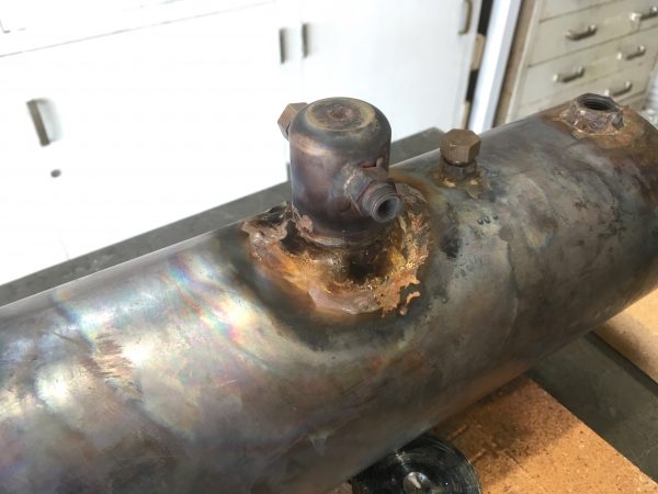
The running theme in that last article was how many decisions and actions made previously had come back to haunt me at the brazing stage. Things like not-perfectly-fitting ferrules, overly-large flat surfaces on cylinders, and so forth. We had one last action that would haunt us- the use of Loctite 569 hydraulic sealant on the electric heating element and thermoswitch (rather than its less nuclear cousin Loctite 545). The problem is that the 569 is a little too good, and after a few brief attempts, it was clear a great deal of force was going to be required to remove them. This is a feature rather than a bug, since these are the two largest holes in the structure, and it’s rather nice to know I never really have to worry about them leaking. However, I didn’t want to risk trying to remove them, because I was concerned about damaging the silver solder joints on their respective mounting bosses. The bosses have hex profiles on them so I can use a double-wrench approach, but I was concerned that might not be safe enough given how much force seems to now be required. In any case, the point of all this is that I was left with a problem. Allow me to explain.
After any silver soldering operation, the piece in question is left in quite a state. It will be covered in flux residue, misplaced solder, soot, heat discoloration, oxidation, the blood of the fallen, and general crud of mysterious origins. The usual solution to this is a pickling bath. “Pickling” is a colloquial term for soaking a part in an acid for a period of time to clean it up. Typically sulfuric acid is used for big jobs, or citric acid for things like jewelry. There are also more sophisticated products, such as Sparex, which is a sulfuric acid mixture that has some additives to help prevent pitting and other undesirable effects. Sparex is tailored to the type of metal, with “No. 2” being suitable for brass and copper.
Thus, the ideal solution (pardon the pun) here would be to mix up a very large batch of pickling acid and dunk the whole boiler in it for a while. However, I was concerned that the heating element and thermoswitch would be damaged by that, and as I just explained, removing them is now kinda off the table. Thus, I opted for mechanical cleanup.
I won’t lie, this was a lot of work. All told, I probably put around 20 hours of sanding, filing, polishing, scotch-briting, cleaning, etc into this piece. I won’t say it was the best way to do it, but I don’t really mind the work. Sometimes it’s nice to have a big block of mindless work to do, where you can put on a good podcast or music, and settle in for a while. There are no hard decisions to make, no machining mistakes to stress about, no fretting about materials or dimensions or anything. Just you, some sandpaper, a needle file, and time to let the mind wander.
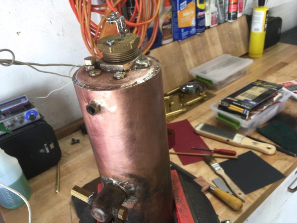
Initial cleanup was done with files, picks, Scotchbrite, and 220 grit sandpaper. I then worked the sandpaper down to 400, 800, and 2000. I wasn’t going for a mirror-finish here. This is a working machine, not a trailer queen. It’s going to tarnish and get water-spotted from use anyway. I was just going for “nice”.
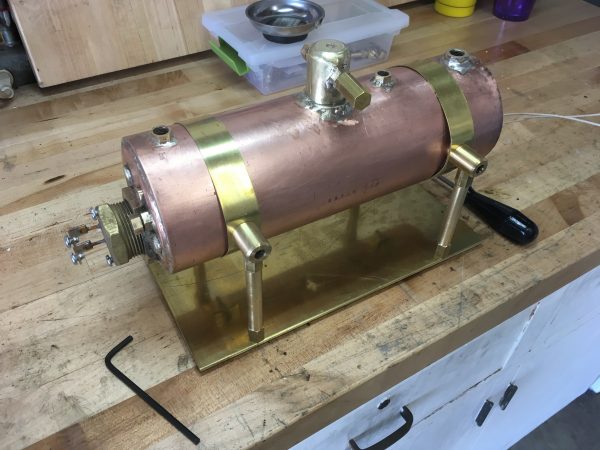
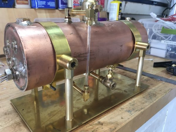
With all that work behind us, it’s time make some accessories! A boiler is more than just a tube that heats up water. It’s a system of elements that work together to efficiently process water and heat into energy that can do work. One of the most critical parts of that system is the water level. Water level management is a core skill of steam engine operation. If the level gets too low, the burner will overheat and something will get damaged. In my case, the electric immersion heating element must remain submerged or it will self destruct. If the water level is too high, it will contaminate the steam with too much moisture, potentially hydrolocking cylinders and causing other woe.
This makes the water gauge a critical bit of apparatus for the boiler. It’s not just a convenience thing for knowing when to put your toys away. It’s as important as the oil pressure gauge on an internal combustion engine (back when cars had gauges) and must be monitored at all times.
The core of the water gauge is a glass tube. This is low tech stuff. The glass tube is connected to the top and bottom of the boiler, to equalize the pressure and allow air to vent through it as needed. Sealing a glass tube against copper or brass piping requires some finesse, so there are a lot of fiddly components involved. I opted to buy a water gauge kit from PM Research rather than attempt to make this myself. In hindsight, it’s not that complex, really, and I could have done it. It’s nice to see how a proper one is built though, as reference for future DIY efforts.
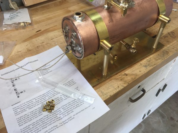
The gauge consists of elbow fittings at the top and bottom, with a glass tube in the middle. The tube has packing nuts that slide over it and compress gasket material against the elbow fittings to seal the glass. This is a primitive but amazingly effective system. The elbows will often have additional holes above and below for whistles, accessories, drain valves, or whatever you like. The true purpose of these extra holes is that it allows you to feed the glass tube in from one end while the fittings are attached to the boiler. This makes installing the gauge easy, because the elbows can be twisted into place first before the glass is installed.
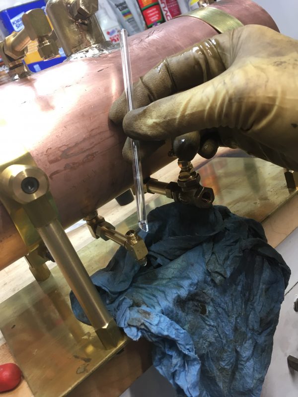
Here’s where I got into some trouble. Remember way back when I was saying how it’s important to get the fittings on top and below the boiler exactly opposite each other? This is why. When you have elbow fittings coming off the centerline of the boiler, if that centerline is off, your horizontal pipe won’t be parallel to the horizontal plane of the boiler. If you have two such pipes, like in our water gauge, they won’t be parallel. This needs to be quite precise, because as any misguided finch knows, glass doesn’t bend. Furthermore, the horizontal extension pipes magnify any error in your fitting alignment. I got into a place where the glass tube just barely fit through the fittings, but the alignment was off enough that the tube wasn’t well centered in those fittings.
After installation, I tried filling the boiler with water. Because the alignment wasn’t perfect, the glass tube leaked. When I tried to tighten the packing nuts just a tiny bit to seal the leak…
I had a dilemma now. Fixing the alignment of the existing fittings was extremely difficult at this stage because the holes in the boiler are where they are. What to do? Well, if you can’t make it perfect, make it adjustable. What I needed was a flexible section that could be bent to get the water glass back in alignment.
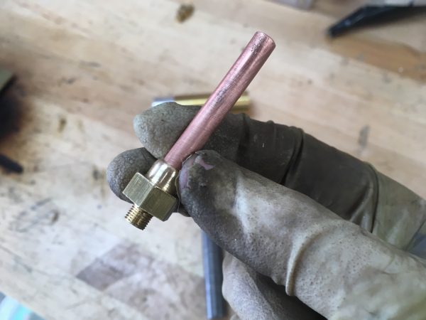
The junk pile provided some ¼” copper tubing from an old refrigerator. A section of this seemed like the perfect thing to help align my gauge.
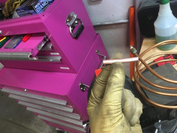
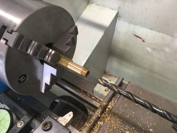
I needed fittings at the top and bottom of my new pipe to adapt it to the existing plumbing. Back to the lathe!
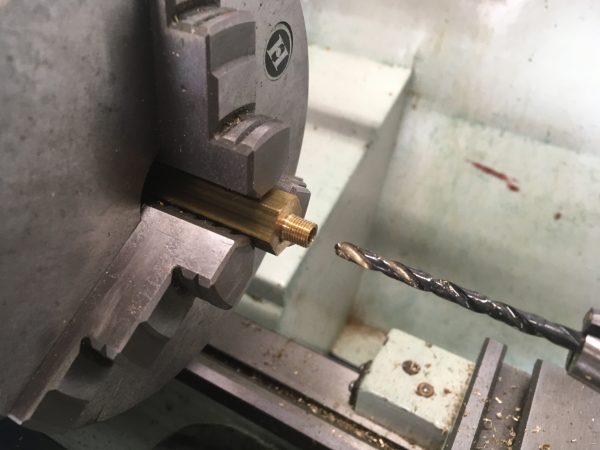
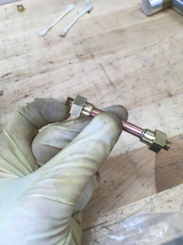
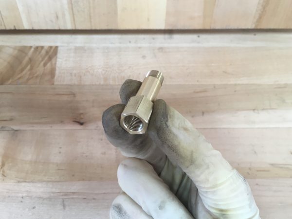
The other end was going to silver soldered to the pipe, so it got a decorative filet and nothing else.
Repeat for the other side and Bob’s your uncle.
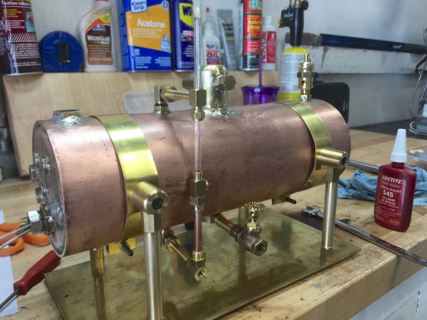
Note in that last photo how the glass tube is now much too long. We need to cut it to length. This turns out to be really easy. All you need to do is file a small “nick” in the side of the tube with a triangular needle file. Then, wearing gloves and safety glasses, apply bending pressure at the nick with your thumbs. Just when you think surely the glass is about to explode into a million shards, forever scarring your entire body, it will “pop” into two perfect pieces. It’s kinda magical.
Something else of note here is the extra elbow I had to make to go under the new steam extension pipe. The fitting itself is uninteresting, except that it’s the one that made me a True Believer™ in Loctite 545. I don’t know what my mistake was exactly, but the threads on that elbow are a truly dreadful fit. The threads are so sloppy you can actually wiggle the piece with your fingers when it’s ostensibly tight. Shameful. Of course, it leaked like a fountain. A dab of Loctite 545, however, and it’s tight as a drum. The amazing thing is, the fitting is still loose, but still seals pressure while you wiggle it. Yes, Loctite 545 (and its burly cousin 569) is amazing stuff. I’m still going to remake that fitting for the good of the universe, but for now it’s serviceable thanks to whatever voodoo is in that little tube of 545.
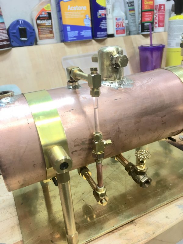
I sized the new extension pipe so that the water level at the bottom of the glass is the lowest it should be allowed to go (when the heating element is barely immersed). About ⅔ of the way up the glass is the maximum fill point (before water starts to splash into the steam dome). This is a very usable range, even though the glass looks like it’s only covering a narrow range of the boiler’s capacity.
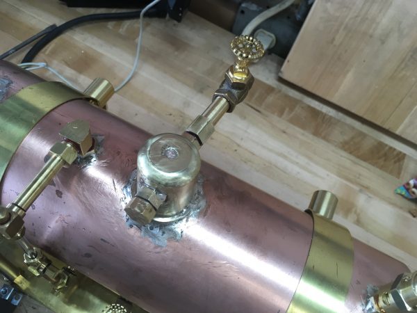
One of the final accessories we need is a “throttle” or regulator for steam pressure coming out of the dome to feed the engine. I’m using a simple globe valve purchased from PM Research for this. That’s not strictly the correct way to moderate steam pressure, but it’s reasonably effective for simple engines. However, I had another new problem.
Designing steam systems is very much an exercise in visualizing the clearance needed to install fittings. Everything has to screw in place, so you need to make sure the parts in question can spin the way they need to. You need to think about the order of operations of installing those parts to make sure it’s even possible to assemble. In this case, there wasn’t room to install the globe valve on the steam dome, because the valve stem didn’t have clearance to spin while the valve body was threaded on the steam dome outlet. An extension pipe would fix this, so it’s back to the lathe for yet another fitting. A steam fitter’s job is never done.
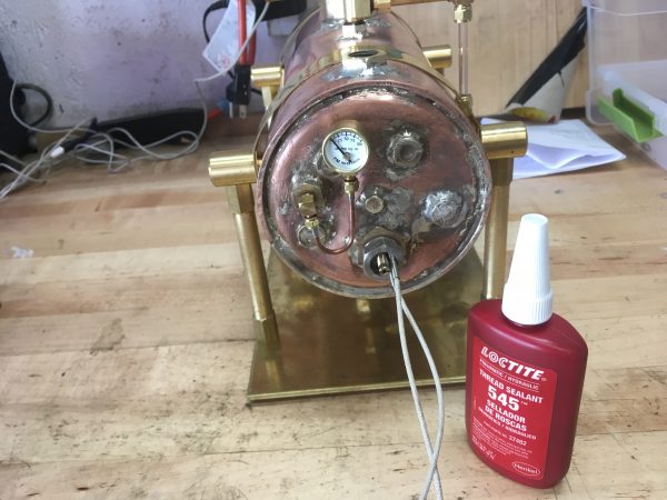
The final accessory we need is very important- the pressure gauge! I opted not to try and make this part, since it’s quite important that it be accurate. Once again, I went to the fine folks at PM Research for the part.
There’s an interesting aspect to pressure gauges- the siphon tube. You may have seen this before- there’s always an extra curl or loop of pipe in the connection between the gauge and the vessel. It looks decorative, but serves an important purpose. Measuring the pressure of a hot gas is tricky business, because hot gases can do a lot of damage. You need a gauge with a robust internal structure to tolerate that. There’s also the problem of pressure fluctuations. You want a gauge that reads a stable rolling average of pressure, not something that jumps around with every twitch. A siphon tube solves both these problems. The tube is filled with water, which serves to insulate the gauge from the hot steam. The tube also cools the water (because of its exposed length) and serves to condense any steam that makes it in there. The hot steam/water pushes on the cool water in the tube, which pushes on the gauge. This allows use of a much simpler and cheaper gauge for an otherwise demanding environment. Lastly, the mass of the water helps to dampen changes in pressure, creating a more even reading and thus a more useful gauge.
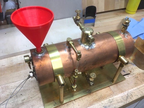
The last thing I’ll talk about on this boiler is the simple-seeming problem of filling it. I made the fill plug as large as practical to make filling easy, but it still needs a funnel. I didn’t have the right size funnel on hand, but it occurred to me that I could 3D print one! This seems like a great application of that machine, and I’m always looking for excuses to justify the investment. In a few minutes I was able to lay out the exact profile I wanted in Fusion 360, hit Revolve, and fire it to the printer. Then the fun started.
My Printrbot has been pretty reliable as 3D printers go, but that’s a low bar. Consumer-grade FDM printers are not plug-and-play tools. Every time you use it, it’s practically a project in itself. Sometimes more than others. This time a lot.
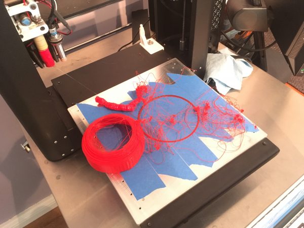
Well, I thought to myself, this happens sometimes. Prints fail, so you clean off the bed and start them again, and things are fine, right? Hoo boy.
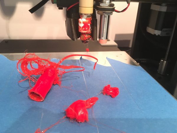
By the time I caught this failure, the hot end was ruined. Everything was covered in burnt plastic slag and the whole extruder had self-destructed.
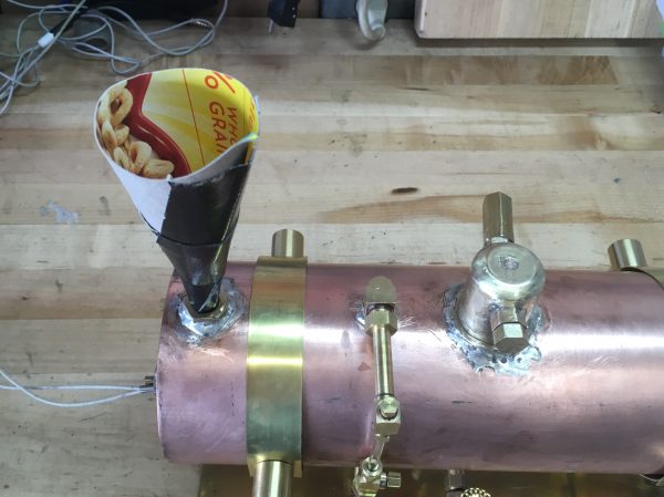
When the fancy toys let you down, it pays to go old-school. After all that, you know how I ended up filling my boiler? A cereal box and Gorilla Tape.
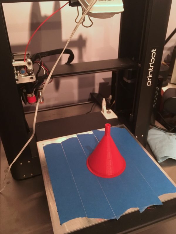
I got a new hot-end for the printer and installed it, but then it wouldn’t print properly. Test cubes on the new extruder were all coming out slanted vertically. Some analysis determined that the printer was skipping steps on the Y-axis, which generally means drive problems. I took the bottom end of the printer apart, and found the set screw on the Y-axis drive belt had stripped itself out, possibly when one of those print failures happened. Or maybe the failing Y-axis caused those failures. Hard to say. In any case, after some TLC, the Printrbot stopped pouting and did what I needed and produced a funnel.
Okay, that about wraps up this little adventure. With the accessories all built, we’re about ready to make some steam! Amazing! Stay tuned, because you won’t want to miss that. Trust me on this. Shit’s about to get cray cray.
what you think about printrbot calling it quits? and did that affect the prices of the replacement parts?
It was certainly disappointing, because I liked what they were doing. As for parts, to be honest, the only PrintrBot-specific piece in those machines is the firmware. The rest is just linear rails, steppers, and hardware you can buy from McMaster Carr (probably where they were getting it). There are some metal framework parts that are unique, but those aren’t going to fail, so I don’t think parts will be a problem.
Oh no… I didn’t know they called it quits. 🙁 I have the same printer. I’m glad I stocked up on parts.
For adhesion on the printrbot, give buildtak a try. It works so much better than blue tape.
My super-adhesion trick is ABS slurry, spread on the kapton tape. Even if I’m not printing ABS. I’ve had almost no adhesion problems since I started doing that. Well, that’s not true. It sticks TOO well, it’s hard to remove prints sometimes.
Yah, I use the slurry when printing ABS and it’s amazing. It really does stick *too* well, to the point that I don’t use it unless really needed.
I didn’t know it worked on non-ABS filaments also though. Thanks for that tip!
I’ve found PEI sheets work very well for bed adhesion, and they’re relatively cheap on Amazon. Whatever bed material you use, make sure you wipe the bed down with acetone or alcohol before you print – any oil from your fingers will prevent adhesion. Oddly, I find that I have to switch back and forth between alcohol and acetone – whenever parts stop sticking, I clean the bed with whatever solvent I haven’t used for a while and they stick again.
Bed temperature is important for adhesion – if your parts come loose, turn the bed up a few degrees. If you printer room is drafty, that can cause problems too.
Part design plays a part in bed adhesion, as well – large ABS parts will invariably warp off the bed unless you have a heated build chamber (or its really hot in your printing room). Sometimes you can add small pads to corners or thin sections to get them to stick better.
I find that a cheap wood chisel is helpful for getting off parts that are stuck too well.
i used the stock kapton square by itself for years before i broke out my roll of blue tape. i would just wipe it down with alcohol, so long as the surface was clean the print would adhere to it. then came the day where i thought id go get me a putty knife to remove prints instead of the utility razor blade. up till that point i hadn’t been cut or stabbed with the blade while removing prints nor damage the kapton surface. i did all three of those things while trying to remove an extra sticky print with the new tool purchased to do that one specific job.
i attempted to replace it with new kapton, but to save money and to “never buy kapton again” i decided to get it in the form of a 5 inch roll from a guy on ebay that specializes on weird widths of tape, unfortunately when applied it was not as durable as the thick kapton layer that came stock with the printer. needless to say that got removed and replaced with a layer of blue that looks like i haven’t changed it in a year. it adheres ok, with the same alcohol trick and if it aint broke.