The pressure builds in this strange new endeavor.
This new project will be a very interesting one indeed. I’ll be way outside my wheelhouse here, and I’m going to learn a lot (and maybe blow up a lot) along the way.
Recently I’ve been building steam engines, and that has been a lot of fun. However, if we’re being honest, they have really been “compressed air engines”. The “engine” in a steam engine is only half the equation. You need steam! It’s right there in the name! Steam engines are rather different than internal combustion engines in this way. A gasoline engine is self-contained, because the power source is a very convenient form of liquid energy storage. For a steam engine, the whole system is really two equally important parts- the engine and the boiler. There is at least as much engineering that goes into the boiler as the engine itself. Perhaps more so! The more I read about boiler design, the more impressed I am with the sophistication of the state of the art at the time. Steam engines are so much simpler than their internal combustion counterparts largely because the boiler is doing half the job. The point of all this is, without a boiler, we’re just faffing about like kittens in a chemistry lab
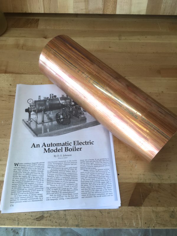
Okay, so I knew I wanted to build a real pressurized steam boiler to run my engines. That’s all hunky dory. However, boilers need a source of heat, and this is typically in the form of combustion. People run small boilers on butane, propane, sterno, solid fuel pellets of various types, and so on. These all involve open flame, noxious fumes, toxic gases, and are generally not things you want to run indoors. Then one day, I pulled my copy of volume 2 of Steam And Stirling Engines You Can Build off the shelf. This is a trilogy of books that are now out of print, but can be found at used book sellers. They are a compilation of some of the best projects from Live Steam magazine. For those under 30, a “magazine” was a thing inked on to dead trees that was delivered to your house on a monthly basis. It was like a very-slowly-updating website filled with blogs. Sure, the refresh rate was poor, but at least you could read it in the bathtub. Back to the point, hidden in the back of this book was a project for an electric steam boiler. What a great idea! All the fun of live steam without the carbon monoxide poisoning. I was hooked and knew I had to build it. The article in question is in two parts, and ran in September and October of 1991. The author and designer of this boiler is D.E. Johnson. I’m not going to post a PDF of the article here, since it is still under copyright and Live Steam will happily sell it to you as a back issue. You can also find it in the Steam and Stirling books (vol 2) as I did.
The first thing to do was start acquiring parts. I immediately learned this was going to be challenging, because while 1991 doesn’t seem so long ago (at my age, anyway), a lot of the parts he references are no longer available. Other parts are still available, but at obscene prices. The latter problem was largely unavoidable. Make no mistake, this is an expensive project. You can defer the costs over time, however, because it is also a very lengthy project. It turns out high pressure steam boilers are actually quite complicated, and we’re going to learn a whole lot of steam engineering principles along the way.
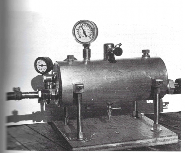
The basic design is that there is an electric heating element inside the boiler, with connections sticking out one end, to be wired to power. Everything else is pretty standard equipment for any boiler. All that is different is that we’re “firing” the boiler to heat the water with electrons instead of dead dinosaurs.
The nicest design feature of this boiler is that the shell is a single piece of 4″ Schedule L copper water pipe. This is easy to acquire, has a wall thickness of nearly 1/8″ (and thus will easily handle the pressure), and saves us the enormous difficulty of making a pressure-tight cylinder from flat stock. It will also look very sharp because copper is pretty. You know what else copper is? Very expensive. Copper prices have gone through the roof since 1991, probably because the supply is fixed and most of the planet has now decided this whole “first world” standard of living of thing is a pretty great idea. Remember from math class how the volume of an object increases with the cube of its dimensions? Well, you really feel that when you’re paying by the atom for all that volume. I honestly wonder if Mr. Johnson would choose the same design given modern copper prices. That said, the money is plenty worth it to me to avoid trying to make a big cylinder some other way (or use a boring or ugly material). If I ever make a bigger one, I might try to repurpose an old air compressor tank, although there will be corrosion issues to deal with in that case. Interesting side note- the article calls for a 9″ long boiler, but since this pipe is sold by the foot, I’m going to make it 12″ long. No sense throwing away 3″ of expensive material. That turned out to be essential for other reasons, as we’ll see.
I started by pricing out 4″ copper pipe at some local metal suppliers. Once I had finished my recovery in the cardiac intensive care unit, it became clear I was going to need an alternative source. I had heard that people overseas use eBay for random off-cuts of metal stock because they don’t have the resources locally that we do in North America. I decided to try that and my eyes were opened to the incredible array of metal scrap suppliers on eBay. Even with shipping, it was much cheaper for a small quantity to buy from someone on eBay. Since then I’ve done a lot more of this, and two suppliers I really like are Stoner Metals and Temco Industrial. Both package well and ship very quickly.
The next challenge was acquiring the heating element. The article very helpfully does the math for us to compute how much heat we need to make for a boiler of this size. His math comes out to 1000W at 8 amps for the heating element. He even supplies part numbers for the parts he used…. which haven’t been in production for 20 years. Rut roh, Scooby Doo. The challenge is to find a kilowatt heating element and matching thermoswitch. In order to hold the pressure, the heating element needs to be turned on and off automatically to hold the water at a given temperature. This isn’t a glorified tea kettle we’re building here- it’s a positive-feedback steam pressure control system.
Because of the power level needed we’re into the realm of industrial process components. As I said, no mere tea kettle element is going to do the job here. That means, of course, that the prices triple. Remember how I said this was an expensive project? Wait until you price out industrial immersion water heating equipment.
Some quality time with a web browser netted the part I needed at McMaster Carr.
Finding a modern equivalent to Mr. Johnson’s 1000W heater was pretty straightforward, but his design relies on a 10 amp thermoswitch. Near as I can tell, those simply don’t exist anymore. For switching a load that large, you are expected to use an intermediate relay. Perhaps thermoswitches this big no longer exist for safety reasons, or changes in industrial systems design rendered them unnecessary, I’m not sure. I suppose now that everything is digitally controlled, a large current thermoswitch is a pointless thing. All anyone wants now is things that connect to microcontrollers. In any case, my design was going to need a relay. Specifically, since this is a large AC load, we need a “contactor”. A contactor is a special class of relay that is designed specifically to make and break AC circuits cleanly. AC really likes to spark over a gap, so if you naïvely use a normal relay, the contacts will corrode quickly due to arcing. Contactors use various methods to get around this, but the most common is “zero-crossing”. Remember how AC current oscillates in polarity 60 (or 50) times per second? That means 60 times per second, the voltage is actually zero. If you detect this moment and use it to break the circuit, there will be no arc and your relay won’t eat itself inside of a week. Neato! Oh, also, industrial contactors are really expensive. Because of course they are. I had to wing it here on the specs, because the original design used no such part. I came up with this one at McMaster Carr, but I honestly don’t know if it’s the best choice. This is an area of electronics where I have very little experience, so I’m rolling the dice with my wallet a bit.
For a thermoswitch, I was able to find the equivalent low-current version of the one Mr. Johnson used, again at McMaster Carr.
Once I’d figured out the heating element, thermoswitch, and contactor that I needed, I placed an order at McMaster Carr (and tried not to look at the final cost). Now I needed to figure out what the hell I’d just bought.
For starters, I don’t know jack about AC, and even less about industrial process components. It turns out they don’t come with instructions, I suppose because it’s assumed if you’re ordering this stuff that you know what the hell you’re doing. Well, I sure showed them. Anyways, some prodigious googling turned up the datasheet for this contactor (PDF), and I was able to discern how it seemed to want to be wired. AC is not like DC, and contactors are not like relays. Not exactly, anyway.
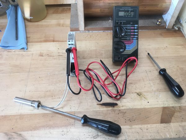
Before going Full Monty, I decided I had better make sure I understood these parts. I put my meter on the thermoswitch and turned the adjustment screw to see how it behaved. I wasn’t sure if it was a variable resistor or a switch. Turns out it’s a switch. Hence the name “thermoswitch”, I guess. I then set it to close just above room temperature. That way I could close it by holding the probe in my hand to warm it up a bit.
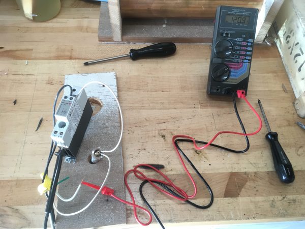
The contactor needs 120VAC to operate, so things got a little dicey at this point. Time to bust out the wire nuts.
Now things are about to get cray cray. You see, I need to test the heating element, but it cannot be run dry. It will be damaged if it is energized while not immersed in water. So let’s immerse it in water! With 120V in the immediate vicinity! What could go wrong?
I grabbed a metal pail and filled it with water, then did my best to arrange things so that the heater and thermocouple were immersed, but nothing electrical was touching anything wet. This was not easy to do, especially since I’m fond of never being electrocuted.
I suspended the components in the water with stiff wire, and clamped the contactor nearby in a way that would keep it dry.
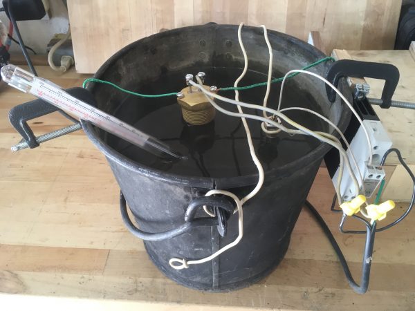
I crossed my fingers, stood somewhere dry, and plugged this beast in. It immediately made noises like tea kettles do when the water is starting to get hot. Very exciting! I clipped a high-temperature candy thermometer in there and the water was very near boiling within a few minutes. I was amazed how fast this large volume of water heated up. 1000W is no joke! This pail is a much larger volume than my boiler will be, so I’m not at all worried about it being powerful enough. Interestingly, the water never actually boiled in this bucket. By chance, it reached a sort of equilibrium at about 205°F (just below boiling). I hypothesize that evaporation from the large top surface area and the heat sink effect of the metal pail held the temperature down such that the heater couldn’t quite push it to 212°F. Plenty of vapor was coming off the water’s surface, but nothing else. That’s just as well, because it may have splashed the electrics if it had actually reached a full boil.
The only issue I had was with the dimensions. These parts are longer than the ones Mr. Johnson designed his boiler around. He chose a 9″ length because that allowed the heater and thermoswitch to sit end-to-end (each inserted through opposite boiler heads). However, my components will fit if I make my boiler 12″ long, which I wanted to do anyway. Kismet! In theory the larger water volume might push the heating element harder to keep the pressure up, but given the roaring success of my terrifying pail test, I have no concern about the heater’s ability to keep up with a little more water.
Overall though, this was really exciting. It seemed like this boiler has a real shot at working, and I was sufficiently confident to start building it.
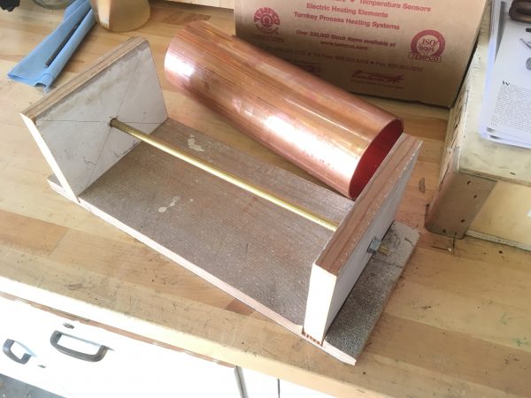
The article helpfully suggests that having a way to hold a large heavy cylinder while working on it is a good idea. Especially for drilling. I agreed and built the jig Mr. Johnson recommends. It also gave me a chance to try making a rabbit joint without a table saw, a technique I learned from See Jane Drill.
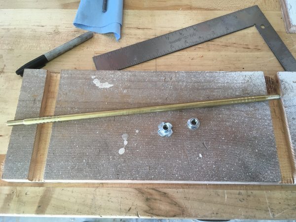
The jig consists of a baseplate, and two vertical endplates held in rabbits. There is a long threaded rod that runs inside the pipe, effectively clamping the wood end plates to the pipe. A simple and effective design.
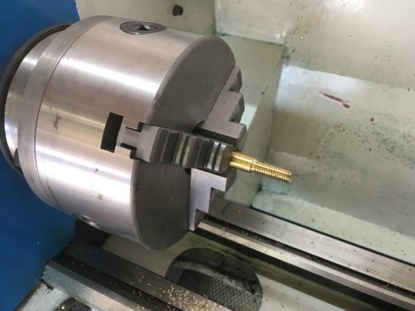
The junk pile happily coughed up some lumber, a T-nut for one end, and a flanged retaining nut for the other. With my super-deluxe threaded rod made, we were ready to try this out.
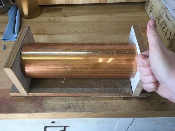
This jig is mostly needed for drilling. Truth be told, I haven’t really used it for much else. Building it as a very first step was probably premature. It was a good reminder that an article like the one I’m following is not a how-to guide. It’s more like a (mostly incomplete) collection of drawings, a few tips for construction, and some photos of what the end result might look like. I find myself deviating a lot from the described project, but that’s okay! We’re in good shape to start real construction on the boiler proper now, so stay tuned for that!
Wow! A kilowatt heater in that small boiler. Who’d a thunk it? Please make sure the relief valve works 100%. I’ve seen what boiler overpressure looks like and you’ll have a very large laundry bill for your underwear if you survive!
The relief valve will be made of cat hair and cheese crackers. That should be fine, I think, because it’s top-dollar cat hair. I don’t skimp on safety.
“shows 120VAC on the output when the probe is warm, and no volts when the probe cools off”
Isn’t that the opposite of what you want? Surely you want 120V switched ON when the water is cold and OFF when it’s hot? Or were you referring to the power to the contactor’s coil and the contactor is NC (normally-closed)?
I think I just wrote it backwards. These things happen.
Cool project. A few comments:
My choice for switching the element would be a solid state relay; they typically run off of 5 volts (ish) (though you may need a dropping resistor) and they switch electronically so they are really rugged. You can find them surplus for cheap (ish), and their input voltage is compatible with many microcontrollers if you wanted to add monitoring.
The wood joint you are using is a “rabbet”.
A contactor is a good choice in this application. They are a specific type of relay designed for large inductive loads, and for preventing arcing on transitions in high voltage circuits. The control voltage is 120VAC, which is another reason a 5V hobby relay would be unsuitable here.
I do hope the gods of spelling will spare me their wrath, for I have angered them so.
8A 120VAC is not a “large inductive load” 🙂 It is a typical household appliance load, and requires no exotic hardware. “Hobby” relays will typically switch 10A loads, inductive or not. If you are getting arcing and think it will damage the contacts, add a snubber of 100ohm and 0.1uF in series across the switch.
A solid state switch is also easily constructed. Use BTA16 triac (~$0.30 on eBay) triggered by a MOC3042 optoisolated controller (~$0.60) and follow the example in its datasheet. It will happily switch up to 16A and can be controlled by 5V logic from your Arduino or whatever. If you don’t feel like working with discrete components, you can buy a packaged SSR for ~$3.50 on eBay.
My god Jim, it’s kittens and waffles all the way down. Load up the tractors and let’s get this party started.
My brother-in-law collects old toy steam engines and it’s been rubbing off a bit, so I’m very excited to see how this build turns out.
also, zero-crossing occurs twice in an oscillation, so 120 (or 100) times per second.
No doubt that detail will save my life someday. I’m in your debt, sir.
You should not be too quick to dismiss “teakettles” for your project. I boil water in mine several times a day. An auto-shutoff kettle will cost you $20 on amazon, will have a 100 degree thermoswitch (which, admittedly, is just a penny-sized piece of deforming copper sheet that pushes the on-switch off), and a 1700W heating element. I bet it would work much better than your expensive industrial contraption.
Temperature controllers for heaters are also cheap and easy to get. For example, look at Inkbird ITC-106VH model for $32, that can regulate temperature up to 400 degrees; comes with a thermocouple and a 40A solid state relay.
I’ll assume you’re in Europe then, and have 240V kettles. In North America, tea kettles top out around 800W because they need to stay under 8 amps to play nice with all the stuff on your kitchen outlet’s circuit breaker. A modern kitchen breaker in North America will be 20 amps, but lots of older houses have 15 amp circuits, and they expect people will run a toaster or other things at the same time.
A bimetal strip style cutoff switch obviously wouldn’t work here, because it can’t be immersed and has to adjustable. 100ºC is also too low of a cutoff for high pressure steam generation.
No, I’m in good old USA. Just search on amazon for auto kettle and you can come up with loads of them. Most are rated at 1500W right in the description. I measured mine directly to draw 1700W. It boils 1.7L of water in 7 minutes.
You do not need to immerse the temperature sensor. Your boiler is already copper and thermally conductive, so just stick a temperature sensor on the wall. The thermocouple that comes with the Inkbird controller (also easy to get separately) will do just fine.
Also, regulating based on pressure, rather than temperature may work better here, because pressure is the actual output you are trying to set.
Great Scott, the world is alive with the sound of French horns, Sally! To the time machine!
I am in Europe, and I quickly googled some teakettles. They easily go up to 2400 W, I noticed. One that I found claims to boil 1,7 liter of water in 119 seconds. I presume that is optimistic, but still pretty darn fast.
Ok, this is the last comment, I promise! 🙂
For real steampunk-style regulation, build a piston-and-spring pressure sensor on your lathe. Then attach the end of the piston outside to a standard light switch. Many light switches use a spring-loaded rocker that smartly snaps over after the handle reaches a particular position. With some trial-and-error you could have an all-in-one electromechanical pressure regulator with hysteresis. Made in brass and bakelite, this contraption will look totally awesome.
Haha, that would be pretty awesome. Maybe if I get this version working, that could be an upgrade.
Whatever you do… don’t burst the boiler. Steam explosions are no joke — the guy who invented the Stirling engine did so because he got tired of losing friends to overworked boilers…
I don’t think I need to say much more than that.
For all of our safety, I wish everyone would lay off explaining to Quinn how things work when she is OBVIOUSLY EXTREMELY KNOWLEDGABLE. As starhawk pointed out, she’s only a few pieces of scrap away from having an (incredibly precise) pipe bomb factory in her house!
Quinn, I was thinking if it might be better to control the heater based on pressure rather than temperature. Might be more direct and precise since a particular pressure is what you actually want. It would also be safer since pressure is what causes the explosion regardless of temperature. Might also want a low water level cutoff since that would be a safety issue as well. You could also go with a PID type controller which would work to keep your pressure really stable just like they do on the hot end of a 3D printer.
The advantage to the PID controller is that it would react to changes in the steam consumption of different steam engines more or less aggressively which would be nice for your application. If you have an engine consuming a lot of steam it will show up as a more rapid drop in pressure so your controller can respond with longer heat on cycles. When you are idling your controller would use shorter cycles to keep things at a simmer.
Here is why I think you want to watch pressure instead of temperature. Pressure is what will make your engines work or blow up your house. Temperature is just the means to get there. The temperature of the water at atmospheric pressure will remain at the boiling point no matter how much steam volume there is. As pressure increases, the boiling points increases and then temperature increases. So pressure is the leading indicator and temperature is the lagging or dependent indicator. If we have our steam valves open and are consuming steam pressure will drop before the temperature falls off and if we slam the valve closed you will see a pressure spike before a temperature spike. The volume of water will cause the temperature response to be slow but the pressure response will be almost instantaneous meaning more responsive control. If you look at a locomotive, they were monitoring pressure not temperature.