Not everything you read on the internet is real.
I think the hacking community online has a bit of a File Drawer Problem. This is a term I’m cribbing from Real Science™ which refers to the fact that very few scientific studies with negative results ever get published. Scientific journals tend not to find them as interesting, and researchers tend not to submit them, all for obvious reasons. Thus, negative results languish in file drawers where nobody ever sees them. However, knowing what doesn’t check out experimentally is actually just as important as knowing what does. This is part of why, for example, every preliminary study that suggests some tiny effect gets reported all over the popular media as the next revolution. Nobody is writing pop science articles in Time about the two hundred previous studies that showed no effect in that same area. People (including other scientists sometimes) get a skewed impression of the state of what is known on a particular topic because all the negative data is sitting in file drawers.
In the case of hacking (and also “Making”, though I find that word tiresome), people only write about the successful things they do. That’s understandable, but the fact is a lot of things we try, particularly if we’ve never done them before, completely fail. That’s great! It means you tried something and learned something. Failures are a necessary part of the process. However, because nobody writes about it, I think it creates a false illusion of the ease of success. It can look to an observer like everyone on the internet is happily cranking out all this great stuff on their first try without much effort. When a new person who is interested goes and tries this stuff, and it fails, they get discouraged. How come they didn’t succeed like all those people on Instructables seem to? Because nobody is writing blogs about the fifty times they tried that thing before they got it right.
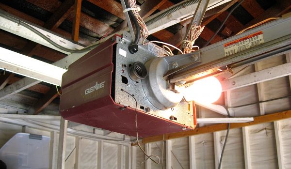
I’m guilty of this myself, and although I have written about one total failure in the past, it’s high time I do so again. This time, it’s a garage door opener. I seem to have an odd fascination with these things, having written about them on at least one other occasion. Maybe I’m drawn to the science fiction aspect of them- it’s a button that you push that makes a wall go away and come back at will! How is that not cool?
Anyways, the current edition of Dunki Freehold has a very nice garage, with a rather annoying garage door. The previous owners only left me one remote for the very elderly opener, so I went and bought another one online. Like everything else, garage door openers are much smaller nowadays, and come in keychain form.
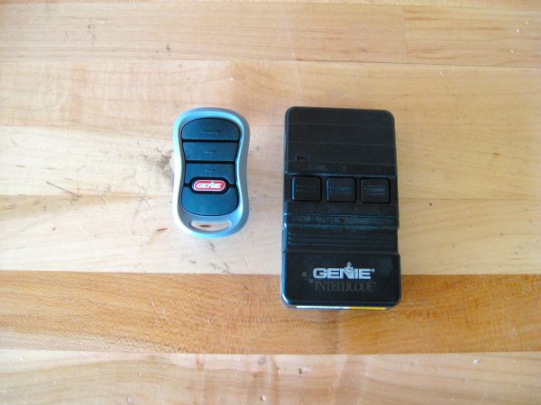
This all seemed fine- the new tiny remote is destined for my daily driver, and clips nicely on to the visor. The bulky old one lives in the weekend car. The old remote works pretty well, so I wasn’t aware of a problem brewing until I got the modern small one. The problem is that the range on the new remote is terrible. Sometimes I have to be only a couple of feet from the door to get it to open. Not very convenient, to say the least. I had been suffering along with this, but then happened across an article online about a simple way to extend the range of garage door remotes.
It seems that there are two things that can reduce the range of an opener- a metal garage door, and a metal roof on the building. As it happens, I have both of those. It’s not surprising that my garage would be a huge sink for radio frequencies. The new remote is much smaller, with a much smaller battery and transmitter antenna. It stands to reason that it is lower power, and might need some help. This article I found claims you can cure this problem by simply relocating the antenna on the opener to a place outside the building.
Here’s where I need to make clear my complete ignorance on this subject. I’m barely an electronics hobbyist, and I certainly know next to nothing about radio antennas, or the design and physics behind them. Based on what little I have gleaned over the years, however this idea does make sense. It is my understanding that the length of a receiving antenna needs to be a multiple of the wavelength of the signal it is receiving. Making the antenna longer doesn’t necessarily improve reception- this is a very common misconception. Sometimes a shorter antenna that is the right ratio to the wavelength is better. If I’m completely wrong about all that, please tell me in the comments.
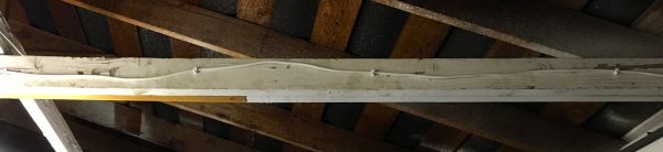
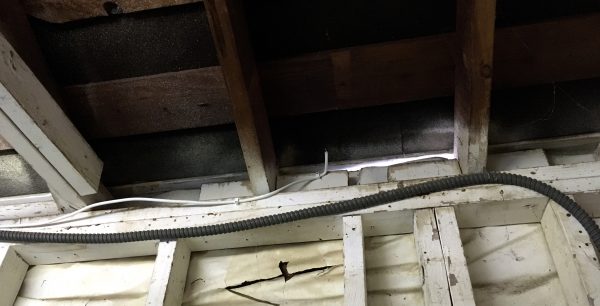
So how do you relocate an antenna without making it longer? By adding a shielded section to it. The article that set me on this goose chase suggested simply running a length of coaxial cable from the original garage door opener to outside the building, then attaching the original antenna to that. Again, based on my limited knowledge, this all seemed to make sense. I happened to have a long chunk of RG6 coax left over from when I gleefully disconnected my cable TV forever (with extreme prejudice), and this seemed like a great way to recycle it.
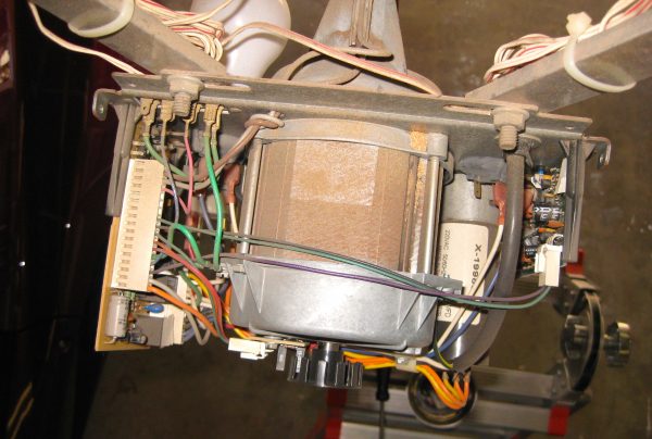
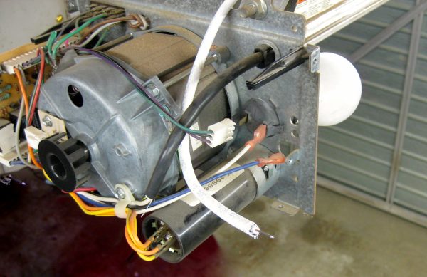
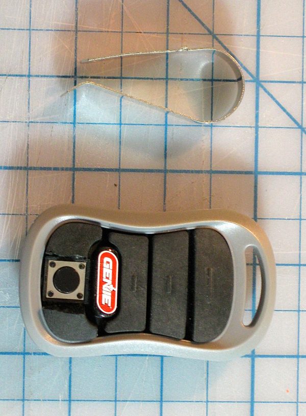
A couple of amusing things about this photo. First, you’ll notice it’s immediately obvious why the light socket on the right (in this photo) wasn’t working. The spade connector has fallen off. Well, that’s an easy win for starters! No doubt it vibrated loose, as garage door openers are pretty much vibration machines. Related to that, notice the field-expedient strain relief on the thick brown/white wire pair in the upper left. Methinks that should have a grommet where it passes through that sharp-edged metal plate, but hey- I’m not a Garage Door Opener Designer. Who am I to say.
Anyhoozle, back to business. Let’s get that digital PCB out of there.
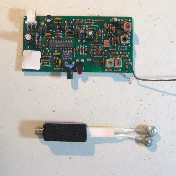
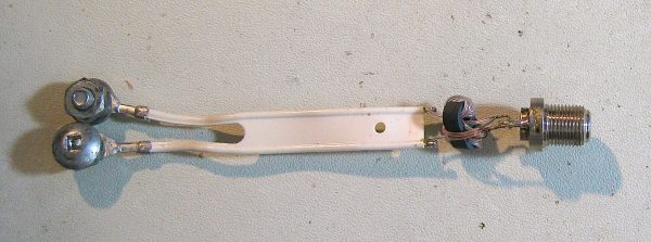
My initial thought was to mount a coaxial connector on the PCB in place of the antenna, so that I can screw a standard cable to it and route as needed. The junk pile coughed up a gem that anyone who grew up in the 1970s will recognize in that photo above- a 75Ω to 300Ω impedance matcher. This was used for things like adapting cable TV to your older television that only had screw terminal connections for an over-the-air antenna (typically rabbit ears). You might have also used one to connect your (then) very modern Atari VCS to your 1968 Electrohome Radiation King.
Note that because this impedance matcher is from Canada, it has the very common (up there) Robertson screws on it. These are not “security screws” as every American insists on calling them. They are in fact a very common format that is vastly superior to the Phillips format that America is obsessed with. Fair warning, if you call it a “security screw” to my face, you will get punched in the pancreas. That is all I have to say on this subject. My soapboxes are weird but very tall. Regular readers know this.
Anyways, this lovely artifact is going to give its life to provide me a nice female coax connector.
Unfortunately, while the coax connector would have fit nicely on the PCB, it quickly became apparent there wasn’t anywhere close to enough room for it inside the garage door opener itself. Clearance in there is very tight. We were going to have to do this less elegantly.
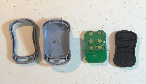
This all seems pretty sweet so far, but I wasn’t done yet. One other thing drives me mad about the new remote. It has those rubber mush buttons that feel like you’re pressing your thumb into the cold bloated thigh of a dead hiker you found in the woods that time. It’s a block of rubber with a conductive pad on the bottom that bridges some traces on a PCB. Whomever invented these buttons is a monster. I’m sorry whoever you are, I’m sure you’re a nice person, but you are a monster. That’s objective fact.
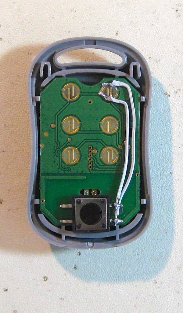
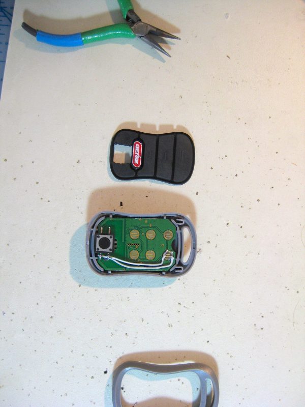
Because of the mushy buttons, it was just as possible that my problems were because I couldn’t tell when I was really pressing the button properly. It was impossible to know because the tactile response is so vague and unhelpful. I decided to attack this problem from both ends by replacing the mush with a mechanical button.
That was an afternoon well spent, right? I have an awesome new remote, and a relocated antenna that massively improved the range? Well, actually, utter and complete fail. The relocated antenna appeared to have no effect whatsoever, and to be honest I have no idea why. It really seemed like this should have worked.
As a hail mary, I reinstalled the original antenna it its original location on the PCB, and tried doubling the length with a piece of the same gauge of wire. Again, referring back to my anecdotal knowledge that “antennas are supposed to be a multiple of the wavelength they are receiving”. This also had no perceptible effect.
I did some more tests at this point, and I’m no longer sure that range is the real problem. There seem to be dead zones and areas where it works well. There’s a spot at the end of the driveway that is pretty far away, but if I hit the button in that small area, it works about 80% of the time. A couple of feet closer or farther, and it doesn’t work at all. There’s something more complex going on here that I don’t understand. If there are experienced radio people in the audience, feel free to chime into the comments with suggestions, or just to tell me how wrong I am about all this. If you’re a dick about it, you’ll get moderated, of course, but if you’ve been moderated in the past, you already know who you are.
The whole adventure wasn’t a total loss. I got to take apart my garage door opener, which was fun, and I did make the remote much more pleasant to use. I’ll keep thinking about this problem, and perhaps inspiration will strike again. In the meantime, here’s one less negative result in the file drawer.
High five for Robertson screws!
I like reading about hacjing/making fails because it reminds me that nobody is perfect.
I hope you’ll post another article someday where you solve the problem by replacing the entire thing by a treadmill with a hamster on steroids, that only starts running when you yell “open Sesame” at the exact right frequency, or something. 🙂
===Jac
My horrible guess as to why this failed is that the cable was either a really bad impedance mismatch or the lack of grounding the shield was causing problems. I have no idea how you find out the proper impedance that the board is expecting. I’d also suspect that if the impedance was wrong against the board, attaching the original antenna also caused problems. Then you’ve got two impedance mismatches which will cause reflected signals, and possibly blocked ones also. Any actual RF experts able to tell me just how wrong I am?
Those low power transmitters are a pain. Probably the same technology as my kid’s crappy remote controlled car that won’t work when it rounds a corner.
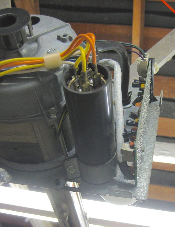
There appears to be only one three pin connector to that pcb. Or maybe three pins plus power? In any case there are only a few wires doing to and from it, so why not brute force the problem and mount the PCB in a plastic enclosure (hello 3d printer!) and mount it to the outside of the garage? Then the antenna would be outside and 10 feet closer to the remote when you’d want to use it.
That’s a great outside-the-box (so to speak) idea! I may just look into that. If I get the entire PCB outside, surely it would improve the situation.
And you’re right- just the three pins. Must be power and ground for the board, and a signal wire (“Go!”) for the power driver circuit. The power driver relies on limit switches at the ends of the track, so it only needs a single pulse to start a cycle.
Hah, knowing that, I’d end up rolling my own implementation with one of those LoRa Radio modules or (dare I say it) an ESP8266.
There’s a chance the old receiver was designed for higher power transmitters and would never work well with modern mini-fobs due to insufficient sensitivity. Short of that, you might have bought a lemon too.
Or did you not use new batteries for the new remote?
Yep, did use new batteries. I am considering doing some kind of wi-fi or internet-based solution instead, but there are security concerns.
Depending on how much outside it actually ends up, it can have the added benefit of allowing a Hollywood Hacker to short the “go” pin and open the door.
What did you do with the shield at the antenna end of the coax? If you just left it floating, it might help to make a ground plane, or at least a dipole. (Not that I’m an expert – I was once a ham, but I’ve forgotten more than I ever knew about antennae.)
BTW, that’s a balun – balanced to unbalanced – transformer, as well as impedance matching.
I left the shielding unconnected. I wasn’t sure if it might have helped to connect it to whatever ground plane the OEM antenna was using, but it didn’t try that.
If there’s only three wires for the controller board (vcc, gnd and “Go”), have you thought about making a replacement board? Perhaps you could even use a Raspberry Pi and then rig up your own WiFi solution. At the very least, you could use ssh to get into the Pi and then run the open_door tool 😀
Well, on the subject of epic fails, I’ve installed two garage door openers. The first one had this strange dangling wire coming out of it, which I promptly chopped off – “must have been shoddy workmanship at the factory…”. The range on that opener was horrible – same as yours. So finally, after 10 years, I got fed up and replaced the entire darn thing.
And of course, guess what? The new opener had that exact same wire coming out of it. Doh! It’s the antenn!. Now the range is amazing. I can be in the next state when I push the button, and voila! The door is open when I turn onto my block!
Moral? Maybe it’s time for a brand new opener Quinn…
Thanks for sharing that, Quinn. I’ve shared a couple of failures online myself and found they were some of my most popular posts. Go figure.
The coax shield needs to be grounded for it to do anything helpful. It usually needs to be connected to something at both ends. If it’s not grounded, it ends up being capacitively coupled to the center conductor, which at RF means your coax was functioning like a fat, bare wire. A long unshielded wire is not right for this job.
The comment on impedance mismatch was right on the money. When the length of a wire is a sizeable fraction of a wavelength of the signal going through it, then transmission line effects come into play and the approximations we use at low frequencies stop working. The voltage along the wire will not be the same everywhere, and there are resonance effects reminiscent of the mechanical waves you probably saw in physics class at some point. It’s tricky to attach a transmission line when you don’t know the source and load impedances. You have to measure them, figure them out by inspecting the circuit, or add a variable matching circuit and “tube for maximum smoke” as a friend of mine called it.
Interesting, thanks! Turns out not everything you read on the Internet is true. Who knew?
Full Disclosure; I am not an expert. So I will chime in and spread possible ignorance. Free of charge.
I doubt highly you can extend the cable through coax without some kind of signal amplification on the antenna side of the cable. From working for a cable company I know it takes a calculated amount of signal just to drive it from the street to end device in the house. So the run no matter how short isn’t free and you are likely dealing with a faint signal to begin with.
I would also question leaving the shield hanging. Just seems wrong. Dangly wires, not my cup of tea. I doubt it has any huge effect, but who knows.
This impedance thing seems to be the crowd favorite and also make sense, and from my understanding of audio and cable I know it to be important there so why not in the RF world. Signal is signal after all.
One last thing on my mind, and this may have been more relevant before you took a knife to the remote… but there is the possibility that you just got a defective remote.
This all could be useless as it is very late/early and I may or may not even know what I am talking about.
Highly commendable of you to admit a fail now and again. I’m sure a boffin will point you in the right direction pretty soon.
Any birds living in your industrial bird house yet?
Not yet. I think I need to make it more enticing with some seed and some bedding.
I very much appreciate your comments on failing and how people tend not to telegraph that information. It has a tendency to give people the impression that someone is nearly always successful.
Speaking personally now, I have a tendency to think that everything you attempt is accomplished upon the first try. I have a tendency to think that every crack a2_4am attempts is accomplished on the first try. Or that the topic of every presentation at KansasFest worked for that speaker. They started. They succeeded. Then the sat back in their chair and smiled knowingly. I tend to think in those moments, “Man, they’re geniuses! There’s no way I could do any of that.” We know that’s generally not true, at least not 100% True.
Granted these thoughts are likely more of a personal issue than anything else, but I do think it’s important to attempt to avoid the impression that of a 100% success rate if one is trying to inform and teach. Mistakes are important. Failure is important. That’s one of the reasons I love this video so much: https://youtu.be/xhQ7d3BK3KQ
I hope you won’t take this as a criticism of what you do here. I think, honestly, you’re more open about your process than a lot of people are. I read your blog and contribute because you’re so open about the process. It’s refreshing and inspiring and I really mean that.
Upon reflection I really just said what you already said but I supposed I needed it to come from my own place, even slightly. 🙂
No worries- I appreciate what you said. What you described is the tone I’m going for here, so I’m glad to hear it comes across. I try to at least allude a little bit to all the things that go wrong along the way when working towards a result.
Full disclosure:
1) I got a degree in chemistry 44 years ago, and have been reading popular science and real science for over 50 years.
2) My father was an electronics/radio guy, civilian for the navy, but I am not an antenna expert. I have tried reading antenna theory, and quantum theory is easier.
In general, your comments about reporting failure are spot on. T Edison reported some thousands of failures at light bulb filament work, and pointed out that each one, he learned one more thing than would not work. Most of the failures I have seen in technical reports are of the form “We tried this, that, and the other thing, with no results, then we …”. Not easy to find or index.
Currently there is an off and on controversy concerning drug testing negative results. In one documented case, four or five different groups did drug trials of the same (failed) substance, at great expense, due to the lack of failure reporting. Very counter productive.
On the subject of the coaxial cable: With both ends of the shield hanging free, not touching the conductor, you have an open-ended Faraday cage. I don’t know how it will affect the signal, but I think it will only interact near the open ends, where near would be a function of the radius and wavelength. Better it should be grounded at both ends, so it would function as a transmission line. Without impedance calculations, either way could work. Experimental science in lieu of years of reading/education.
On the other hand, If your garage has only 2 metal sides, top and front, you do not have a Faraday cage there, and the signal should ‘wrap around’ the sides. However, what you do have is a pair of ratio reflectors. What it sounds like to me is a complex arrangement of destructive interference. Did the working areas change locations when you moved the antenna outside? I had a similar problem with a former cell phone and the reinforcing metal in my chimney next to my dinning room.Move the phone 5 inches and it would go from 4 bars to 1 bar (or less) on the signal display. New phone with a different frequency solved the problem.
Good luck, and let us know if you get it working.
I am not an RF engineer either, but from what I know about R/C planes: straight wire antennae don’t like to pick up signals coming at them end-on, they get the best reception from signals coming perpendicular to the wire direction. (The trick to visualise this is “put a doughnut over the antenna” to see where the best reception comes from) It might be worth fiddling with the orientation of the antenna so you are positioned perpendicular to it in the place where you want to use the opener. Maybe just hang a small weight off the end so it’s hanging straight down without curling?
For those of you saying it’s a good idea to ground to coaxial cable — and because I don’t know the answer to this question — could you explain how you might ground the coaxial cable?
Coax works because it’s shielded, either with braided wire or foil, around the center conductor. It’s this stuff you ground. The classic F-Type coax connector (think TV antennas and cable TV) grounds via the nut you screw on. This design shields it all the way through the connectors as well.
When adding a coax jack to anything, the center conductor is for the signal, and the outside is ground. I believe this ground is usually the circuit’s ground, (- or neutral,) and not earth ground.
As I understand it, Shielding only really works when grounded since it provides a path for the energy absorbed from the RF to dissipate. Left ungrounded, the shielding just absorbs the RF, generates AC voltage in the conductor, then re-emits the RF like an antenna. Grounded, I think it behaves somewhere between a reflector and a sink.
On the receiver side, connect the shielding layer to the opener’s box (if metal), or a ground trace on the circuit board. On the free end, going thru the wall, put up a metal plate and connect to that, or if a stucco wall, dig out out of the wires supporting the stucco, and connect to that.
The brute-force way to extend IR range: https://www.youtube.com/watch?v=_jACSPipPSE
Rather than soldering the old antenna to the coax, I would have just stripped the outer conductor back far enough to be a similar length. Also you should ground the coax on at least one end, otherwise it is effectively part of the antenna.
While it does help if the receiving antenna is tuned to a nearby frequency, the length of the transmitting antenna matters more. ( compare the lengths of the antenna on both the old, and new transmitters. ) I would also bet that the new transmitter doesn’t have near the transmit power of the old one.
I remember driving around in my late teenage years communicating over CB. I had a very well tuned (but cheap) antenna, and the other people hadn’t bothered adjusting the little piece of metal at the end of their very nice twin whips. They could hear me, but I couldn’t hear them.
Seems like a combination of not having the shielding grounded, and having the metal bits here and there causing reflections and therefore interference. If working with RF is something you have an intention of doing on a regular basis, I recommend the purchase of an SWR meter for working on antennas, and a tunable field strength meter for checking reception/transmission. Otherwise, see if you can borrow them.
I could go into details about how to use them, but there are lots of great resources out there aimed at ham radio enthusiasts—and a broad-based survey of the available information is much more likely to produce useful data; the whole point of having meters is to know what works and what doesn’t.
The coax thingie was doomed to fail. The unconnected shield greatly elevated the cable losses (without a properly terminated shield, the cable’s characteristic 75 ohm impedance no longer exists) and even had the shield been properly terminated at both ends, the losses would still be too high for the milliwatt output of the remote.
Also, in many of these “hanging wire” antenna setups, the input circuit’s characteristic impedance is undefined and impossible to match to available components, such as the 300-to-75 ohm balun you tried. I’m speculating that the coax was burying the signal in standing waves due to impedance mismatch between the balun, cable and input circuit.
I think your only real recourse is relocation of the receiver to get the original uni-pole antenna outside of the “Faraday cage” that is your garage.
On the positive side, You should know that those old Genie door openers are nearly indestructible. The motor drives a long shaft with an Acme thread that engages the trolley that pulls and pushes the door. That design was a major selling point with these openers. An occasional shot of Lubri-Plate on the moving parts takes care of maintenance. After 25-30 years of service the motor bearings might need lubrication. Don’t use WD-40 as a lubricant anywhere in the opener.
Lastly, publishing about failed projects is important, if for no other reason than to help others avoid going down the same road. On my POC single-board computer site, I describe the failures (none major to date), as well as the successes. I want readers to realize that no one is immune to the occasional boo-boo, no matter how knowledgeable and skilled.
I’ve had my share of failures over the years, some very expensive (e.g., having a freshly-built big block Chevy come apart at 8500 RPM and dump 10 quarts of oil, along with a couple of rods, on the track) and others quite embarrassing (powering up a newly-designed tube amp for the first time and having it fill the shop with vile-smelling smoke). I wasn’t shy about letting it be known that it had happened. Unlike the pope, I don’t claim infallibility. 🙂