Breathing new life into (not-so-)old crap.
You know, I feel like I could write a whole other blog entitled Making Crap Last a Little Longer. It seems like our world is increasingly surrounded with disposable stuff that isn’t meant to last very long. I don’t know if that’s actually true- it’s possible that our parents’ generation’s stuff just seems more durable because only the durable stuff survived for us to admire. It’s also possible that disposable stuff isn’t a bad thing- if production and recycling are now so efficient that it’s cheaper to replace things, maybe that’s good?
All I know for sure is that I hate it when something that’s only a few years old fails for no good reason. The good news is, most stuff can be brought back to life relatively easily. Modern technology works in our favor here- basic electronics like ICs, PCBs, and so forth are very close to bulletproof. If a gadget breaks, it’s almost certainly because of something trivial that’s easy to fix. Common suspects are anything that can move. Switches, and battery terminals, for example. If something is really old, electrolytic capacitors are a common failure point. Every one of those is an easy repair with off-the-shelf parts, and it usually only takes a few minutes. Furthermore, a device often has a single point of weakness that, when addressed, can double the life of it.
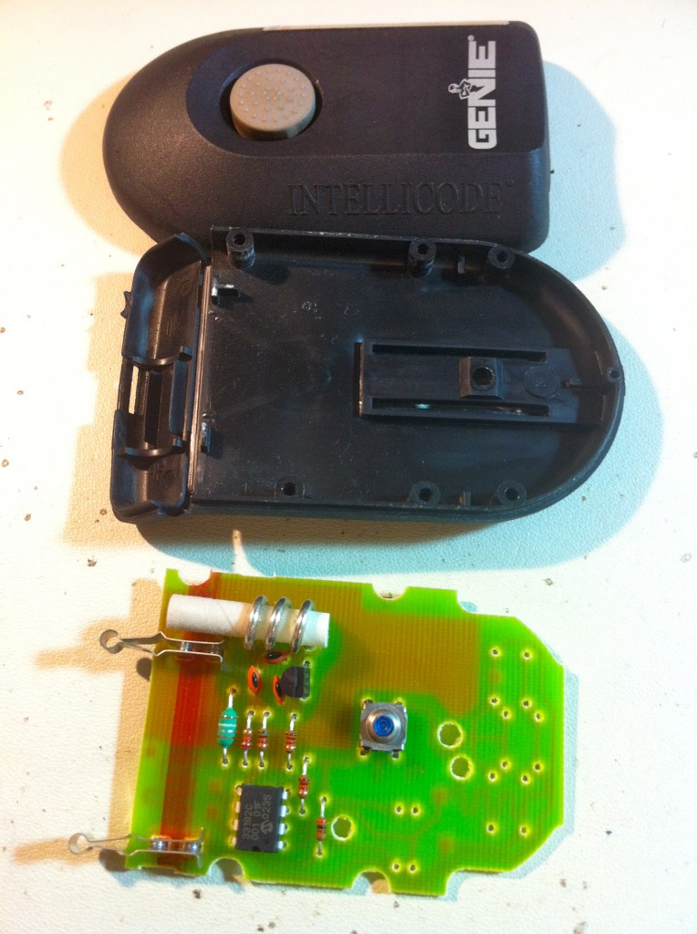
My garage door opener has been acting increasingly flaky over the past couple of months. The door would open partway and stop. Or it would take a couple of presses to get the door to move at all. Finally, last night, it died completely. The opener motor works fine from the hardwired button inside the garage, so clearly the transmitter is at fault. It’s only about six years old, so the failure is very premature, in my book. Time for exploratory surgery!

It’s interesting that there’s room for a bunch of parts that aren’t installed. Looking on the web, there were two levels of upgrade available for this transmitter, which cost $10 or $15 extra. There’s only about 45 cents worth of missing parts here. There’s a moral lesson in that somewhere, but I’m not sure what it is. It’s also interesting that this transmitter could be much, much smaller than it is. The components are hobbyist-size through-hole, the chip is a DIP package, and the PCB is wasting space like it’s going out of style. This could be hacked into a keychain version with surprisingly little effort. I think I’ll add that to the project queue. For the moment, I just need it to work again.
Anyways, since I’m in here, I might as well try to learn something. The section in the upper left is clearly the transmitter. What I don’t know about RF electronics would fill a warehouse, so I’ll leave it at that. If someone would like to chime in on how this works, please do so in the comments. Aside from the transmitter, that 8-pin chip is clearly doing the heavy lifting, so what is it?

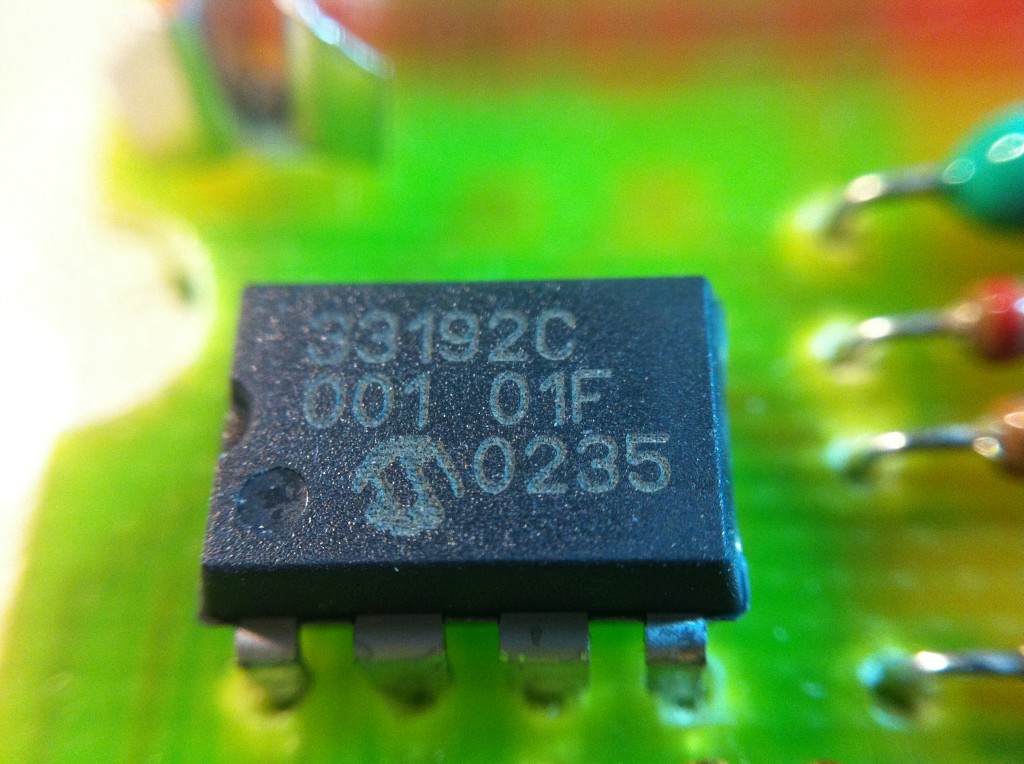
It’s from Microchip, purveyors of such fine products as the hobbyist-friendly PIC microcontrollers. This chip is at least ten years old, so identifying it proved challenging. It likely dates to before datasheets were available online, but I did find something that appears to be a newer version of the same thing:
http://ww1.microchip.com/downloads/en/devicedoc/21143b.pdf
The pinouts look like they match my chip (based on Vss, Vdd, the antenna connection, and the connection to the Open/Close button) and the specs match (based 12V supply, and recommended configuration). My opener is supposed to have some sort of rolling code security system, so it all adds up. Clearly this chip is doing the encoding. Methinks there’s an opportunity to hack this into a home automation system or something similar. So many projects, so little time.
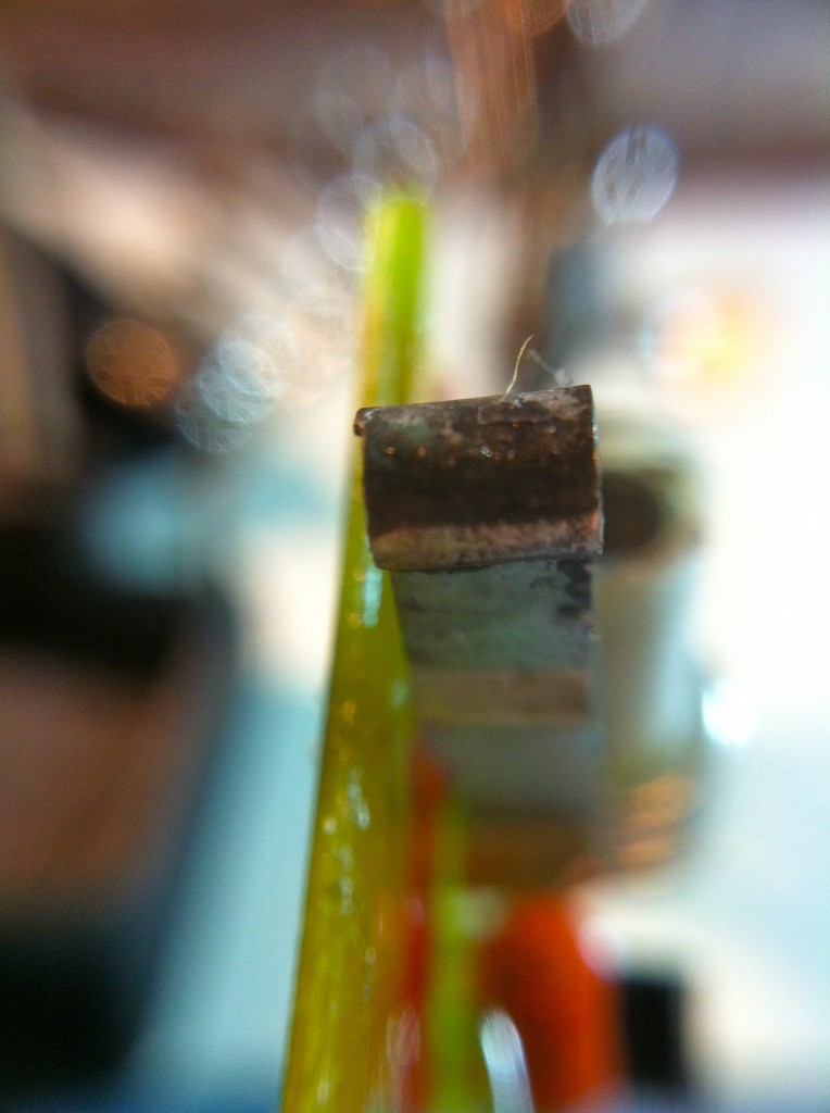
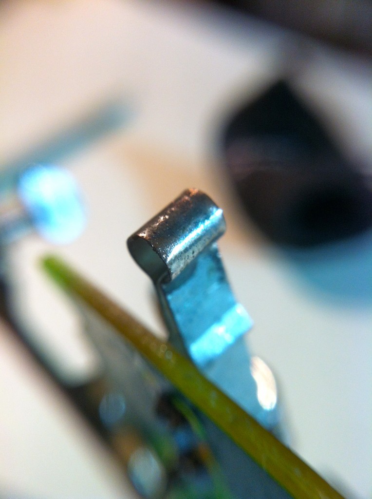
Anyways, back to business. Why isn’t this thing working? Well, a quick visual inspection of the circuit revealed the problem.


The battery itself was fine, and still had full voltage output despite being original to the device. That’s pretty remarkable in itself, since I use it every day. After cleaning up the terminal, the device now works perfectly. Huzzah!
My purpose for writing this article is to encourage people to crack open broken stuff. I’m no electrical engineer, but as I’ve demonstrated here, most of the time points of failure are very simple and quite obvious. Even if you’re not sure what’s wrong and aren’t able to fix it, there’s always a chance to learn something about how it works. Googling a few part numbers is often very educational! It’s also possible I wrote this article entirely so that I could make a joke about a dead German conductor from the early 1970s. I leave that determination as an exercise to the reader.
KeeLoq? Seriously? Just knowing that name makes my brain hurt.
I like the way you think… and tinker.
planned obsolescence is the key cause 🙂
http://www.youtube.com/watch?v=I5DCwN28y8o
That looks a lot like the transmitter for the alarm I put in my motorcycle about 15 years ago. Mine was made by the On/Off company (not kidding). Same mini 12v battery too but your terminals look a little more robust than mine. Mine are just a couple of curved pieces of metal soldered to the PCB.
It’s funny how little power they take. I definitely don’t use it every day but I’m still on my first battery and it’s still full of juice.
“It’s from Microchip, purveyors of such fine products as the hobbyist-friendly Propeller microcontrollers.”
Oops, I think you meant to say PIC microcontrollers, not Propeller.
Whoops! Good catch, thanks! I fixed it. 🙂
I’ve repaired or rebuilt broken stuff before too. Remember waterbeds? They were all the rage in the 80’s but are now forgotten. Anyway the heater failed on the one I owned and I was left with the problem of replacing it. Waterbed heaters consisted of a flat element that was placed under the mattress (which is really just a large water tight plastic bag). Also placed under the mattress was a thermal sensor, an external controller cycles the heater on and off to maintain a constant temperature. My heater was the basic model, the controller was a bi-metal spring connected to the thermal sensor by a tube filled with heat conducting fluid. That spring seemed to have ‘sprung’ on my unit and it would no longer respond to the temperature change and was stuck in the off position even with the temperature setting at full blast.
I could just replace the controller, if they would sell me one. But the only thing the store had was the newer electronic version of the controller, and it was compatible with a different heater. I’d have to drain the mattress to replace the heater and controller. What I did was build my own controller. I used a triac to control the heater power. But how to regulate the temperature? I found I could use a common diode (1n4001) as a temperature sensor. The forward voltage drop across a Si junction varies with temperature. I amplified this difference with a 741 op amp wired as a comparator with a 7805 serving as a voltage reference. A diac opto-isolator coupled the 741 to the triac. I calibrated the controller by putting the diode (wrapped in plastic wrap) in a glass of water using a glass thermometer from my darkroom to measure the water temperature. A 10 turn pot was used to trim the range of the controller and a common 300 degree pot set the operating point. I was able to lift the corner of the mattress to push my diode sensor underneath. I salvaged the connectors and power cord from the dead controller. All of the parts including the case were obtained from the local rat-shack.
My home brew controller kept that bed ‘working’ for another few years.
That sounds like a great hack! My parents actually still have a waterbed. They love it! Most of my family had them at one point, but only one survives to this day.
I love your invention in fixing the problem. We fit garage doors and quite often we have instances where customers have either broken or lost the remote control. We then have to try and source a replacement for them. I recently read a blog post where a guy had managed to configure his Android phone to act as a remote control for his garage door – it was ingenious and I think could be a great solution in future.