Increasing the unexpected usefulness of an odd tool.
Patrons! If you’re at the $5 level or above, you’ll be seeing a three-part video series of all the machining in this project. If you’re at $2 or above, watch your feed for the drawings and models!
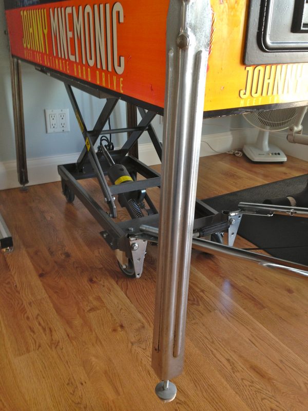
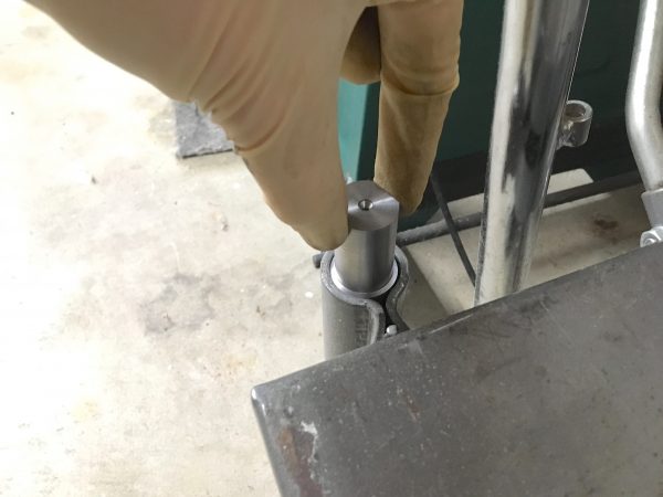
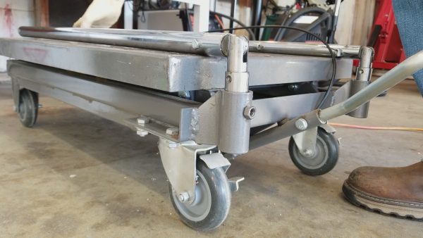
There are tools that you buy that you’re certain are going to be the greatest, most useful things you have ever owned. More often than we like to admit, those tools we were initially most excited about end up in a cupboard, never to be used again. However, the opposite is sometimes true. Sometimes we buy a weird single-purpose tool that we’re mostly convinced is probably a waste of money and we feel bad acquiring it. Then somehow, that tool goes on to be one of the most loved and most used things in the shop. That latter scenario is vastly more rare, so we must treasure the moment when it happens. One such moment for me was the acquisition of a Harbor Freight hydraulic lift cart. If ever there was a more ridiculous single-purpose tool, I haven’t seen it. I bought this complex, heavy, space-absorbing device to do exactly one obscure thing- lift a pinball machine. It’s not even something I do very often. The cruel fact is that pinball machines are obscenely heavy. Modern ones can tip the scales at 600lbs (275kg). Yet moving them is something that a person sometimes has to do by oneself. There are special-purpose devices for this called Pinball Lifts, but they are (as with all limited-market devices) weirdly expensive for what they are. An alternative that is commonly used in hobbyist pinball circles is to buy this Harbor Freight hydraulic lift cart (half the price of a pinball lift) and modify it for use under pinball machines. The key issue is the handle. From the factory, the cart has a rigidly attached vertical handle. The cart needs to slide all the way to the back of a pinball machine (where the center of gravity is), so the handle has to lay flat. The usual modification pinheads make is to remove and re-attach the handle with some heavy gate hinges. It looks ugly, but it does work. Behold:
While the cart is great for that purpose, the crazy thing is that I started using it all the time around the shop. It has become a welding table, a mobile work surface, a material support for the horizontal bandsaw, and more. It stands in for saw horses, hauls heavy steel plate around the shop, lifts heavy things in and out of trucks, allows me to take messy jobs outside, and makes julienne fries. I would never have believed how useful this damn thing is.
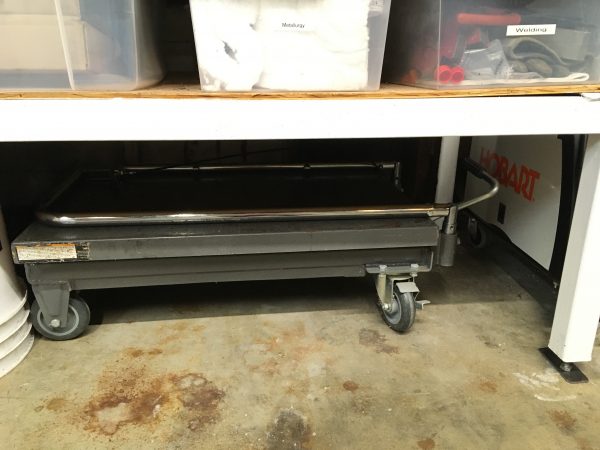
Okay, great! The cart works, it was a heartwarming story, on to the next blog post? Well, it’s not all kittens and unicorns in the land of Blondihacks. You see, there are two problems with this gate-hinge setup. First, the cart no longer functions for its original purpose of being pushed around, because the handle won’t stay upright. You have to drag it around like a petulant puppy. Second, the hinges don’t fold flat in the forward direction, so the cart can’t be stored under anything. It takes up a lot of floor space. What I would really like is some kind of high-tech hinge that would lock in place vertically, fold flat forward, and also fold backwards for use under the pinball machine. A hinge that fancy would probably require a machine shop to make. Oh… wait! I have one of those. Let’s proceed.
As is tradition lately, I started by modeling the problem in Fusion 360. The original handle slides into a pair of collars in the base, so I figured I could leverage that.
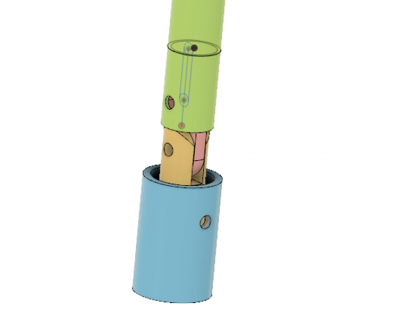
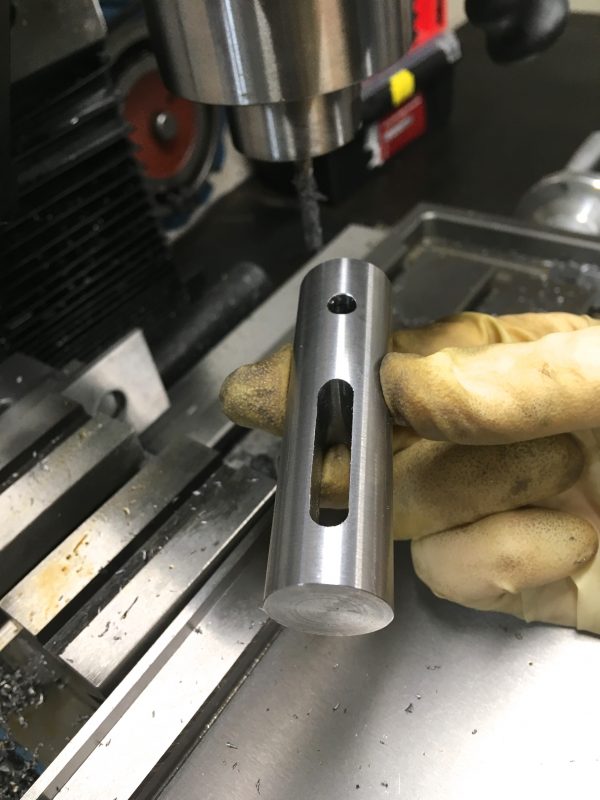
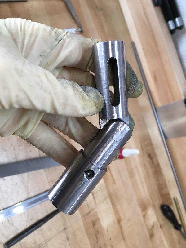
When the handle is slid down, it will be in the factory position, vertically locked. The handle effectively locks the hinge in the vertical position by virtue of sliding over it, and becomes further reinforced by sliding into the base. In the up position, the handle will hinge forward and back. To remain fully attached, the hinge bolts to the base on the bottom, and has a slot in the top so the handle is captive, yet still slides vertically.
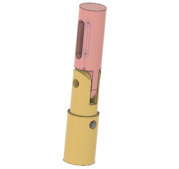
That’s the plan. The universe laughs at the plans of humans, as we’ll see, but it seems like it should work. Complete drawings and 3D models of this project are available to Patrons, so sign up now to see them.
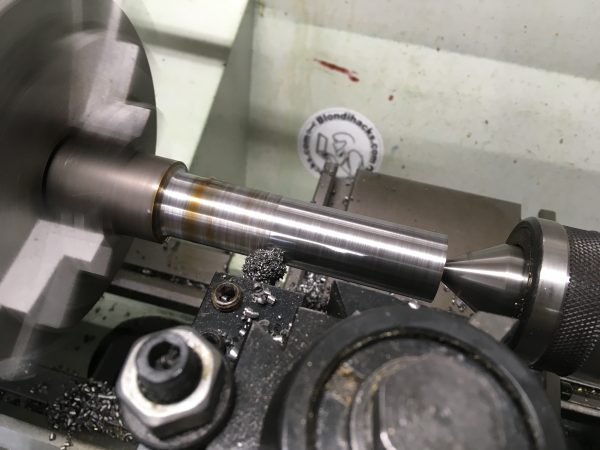
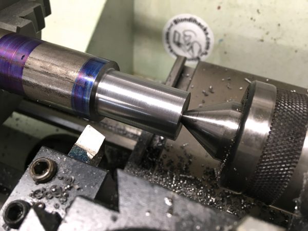
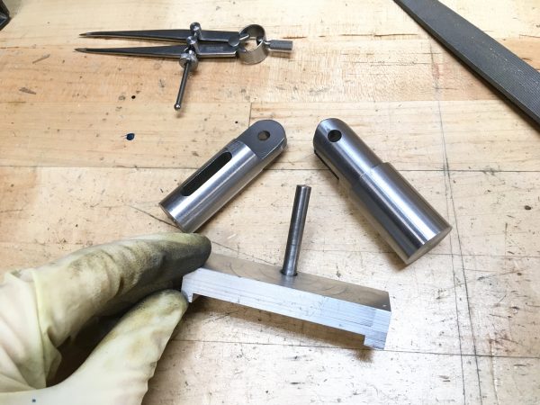
The hinge is made from 12L14 steel, which is a cold-rolled mild steel with a tiny percentage of lead in it to make it nicer to machine. It’s delightful stuff. The only real downside to it is that it welds very poorly. If you’re doing a project that requires machining and welding, best to stick to a traditional mild steel like 1018.
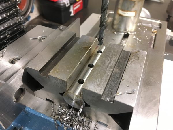
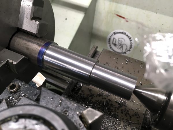
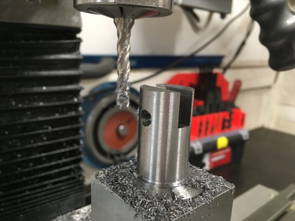
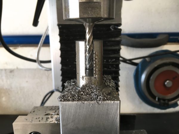
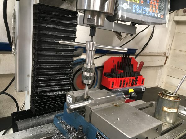
With the largest outer diameter machined, we can start to form the features we will need. The order of operations took some thought, and I can’t say I came up with the best possible way, but this did work. I started with cross-drilling the hinge-pin hole. Over to the mill!
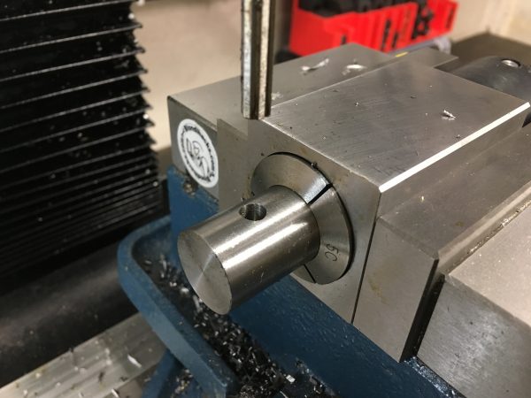
Cross-drilling round stock can be tricky, because any drill is going to wander off that surface. Using a good sharp center drill first is the key. Spotting the hole with that gives the drill a place to go. You can also mill a flat spot with an end mill. This works really well if your hole is not on the very top of the round surface.
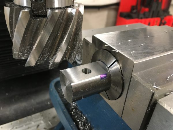
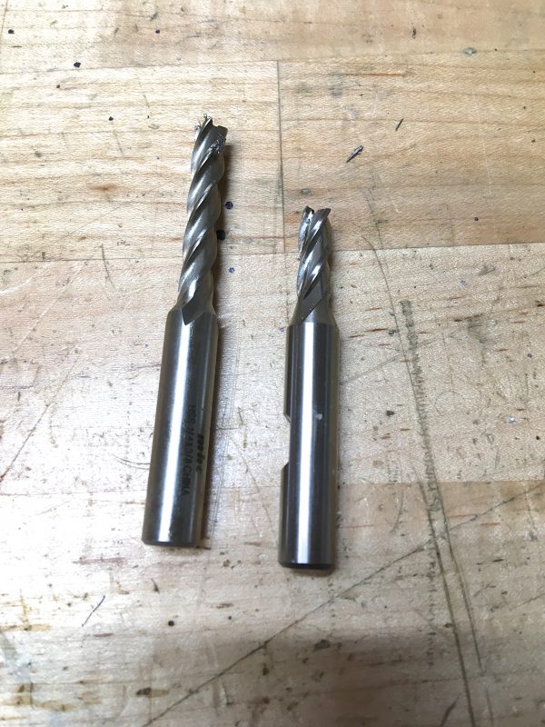
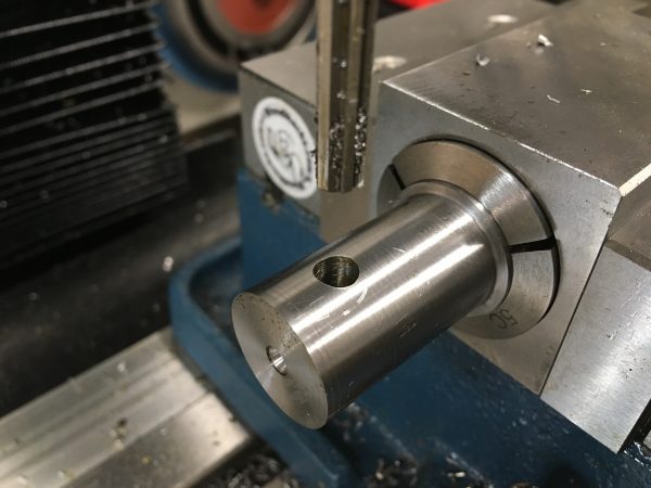
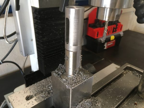
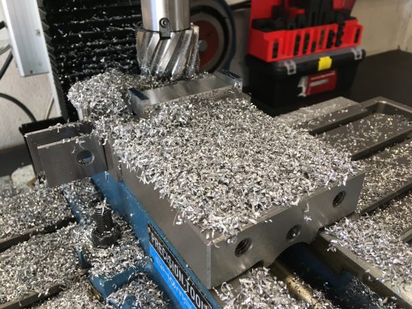
With the cross-hole done, it was time to make the “tab” that forms top portion of the hinge joint. For this, I get to break out one of my favorite new tools- a 2″ cobalt high speed steel shell mill. Shell mills are sort of a cross between an end-mill and a face-mill, and are very versatile. They aren’t cheap, and have less longevity than similar carbide insert tooling, but for a small mill like mine, they are a great choice. A regular end-mill would also be fine here, it would just require more passes.
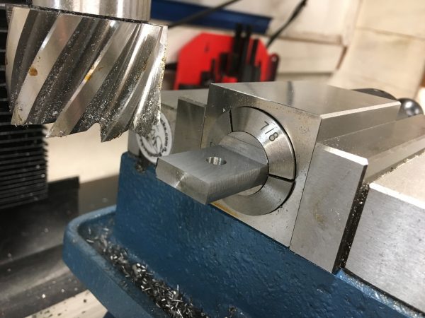
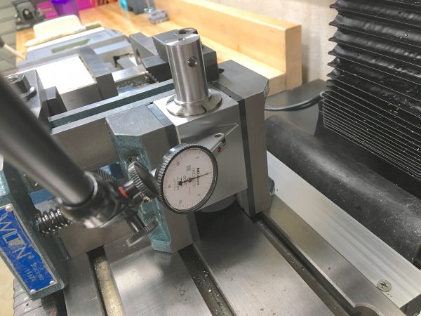
You’ll note that I’m holding the piece in a collet block. That’s not just because it’s an easy way to hold something round. The superpower of collet blocks is that they are indexable. All four surfaces of the block are precision ground, so you can rely on the center axis landing in the same place if you rotate it. Combined with an end stop to get it in the same place laterally, I can mill the other side of this tab simply by flipping the block over. Repeatable setups in machining are very desirable.
The next feature to make is the slot, and the setup here was trickier. In hindsight, there were better ways to do this, but I got the job done, and that’s the main thing.
The reason I did it this way is that, amazingly, it didn’t occur to me to simply mill between the V-blocks right in the vise. It was close, but there was room! Furthermore, a machinist jack would have been a good way to secure the hanging end, but I haven’t gotten around to making one yet. Another option would have been a makeshift jack with some threaded rod and T-nuts, but I didn’t think of that either. But hey, what you see here worked just fine.
The only other trick to this operation is that the slot is quite deep. Too deep for a standard ¼” end mill.
Note that I need two of each of these parts, so when it came time to make the second hinge top, I did realize an easier setup was possible.

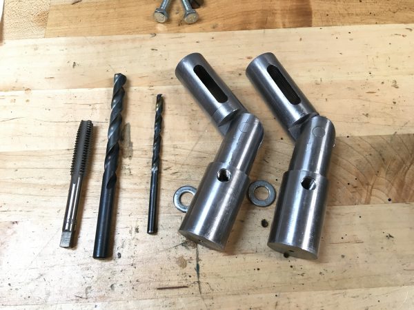
With the hinge tops finished, it was on to the bottoms. These are pretty similar parts.
At this point, before going further, it was useful to do a test fit. The next couple of operations are time-consuming, and if I’ve messed up my drawings, I’d prefer to find out now. As it happens, I did make a few tweaks.
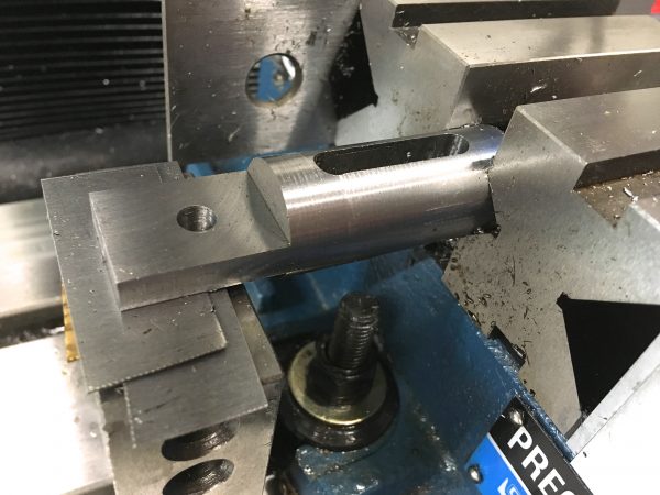
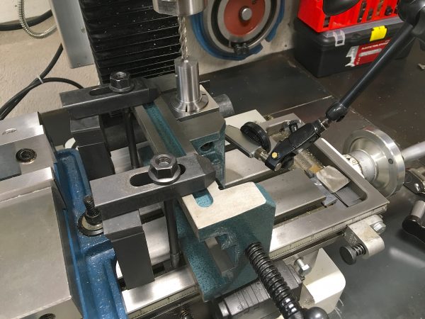
Confident that the part was going to fit, I could move on to cutting the slot. The slot forms the “fork” portion of the hinge, and it’s a little tricky. I wanted a square bottom in the slot for maximum clearance, so that meant it needed to be milled upright. I experimented with a few setups to see what would work the best. If possible, it’s desirable to get a setup that allows milling in the X-direction, because that’s where the power feed is.
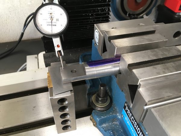
This setup probably would have worked, and would have allowed me to mill in the X direction, but it was too clunky. I spent a little time indicating it in, but it was clear it was going to take shimming and wasn’t a good approach. There were too many variables and sources of imprecision here.
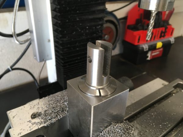
The next thing I tried was simply holding the collet block upright in the mill vise. This is a little tricky because the bottom of the collet block has the tightening nut, which is not a precision-ground surface. I would have to indicate it in vertically. I did this with the stock in an orientation where I could mill in the X-direction, but partway through the job, the collet block slipped sideways in the vise. There wasn’t enough clamping force from the vise alone to hold against the substantial leverage of the collet block sticking up in the air. My third setup would prove to be the charm.
Interestingly, these two “fork” slots came in 5-8 thou oversize. I believe there are several reasons for this. First of all, end mills aren’t great for dimensioning on two sides at once. If the dimension of a slot is critical, you should hog out the middle first, then bring the sides to dimension with a smaller end mill separately. Third, because the end-mill was so long, some amount of deflection and runout is inevitable. Hogging out the slot with an undersized drill first would have helped, so that the end-mill has less work to do (and thus less chance for deflection). Still, for a slot over an inch deep and only 250 thou wide, 5-8 thou tolerance is not bad for this inexpensive end-mill. This slot needs some clearance anyway, since it has to be a free-running fit on the other half of the hinge. It actually worked out great!
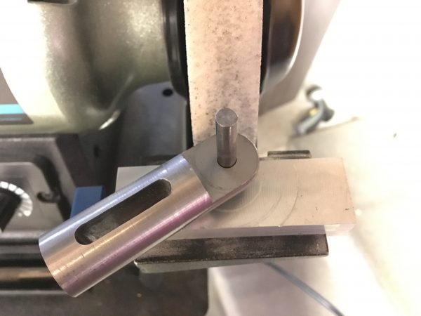
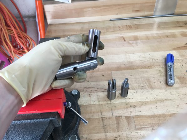
The next task at hand is to round the ends of the four hinge pieces. They need to be rounded so they clear each other when bending. The “most machinist” way to do this would be with a rotary table. This is a special machine you can bolt to the mill table which allows you to rotate work in a very precise way, for milling perfect curves. However, I don’t have one, and they are very fussy to set up. That’s vastly more precision that I need here. For this job, a file or a grinder will work fine. Just for giggles, I decided to take the opportunity to try making a jig for the grinder to see if I could get the curves to come out nicely with minimal setup.
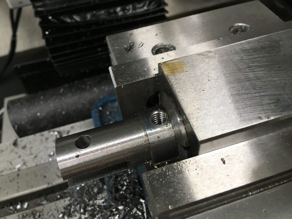
There’s one last operation to do on the hinge bottoms, which I should have done sooner but forgot about.
The last part to make is the hinge pin. For this, I’m using ¼” drill rod, so there’s no machining needed. I cut them a little oversized, and glued them in with Loctite 603.
With the parts finally done, how did it work out? Well, there was one main issue. I didn’t account for how high the table is in the collapsed position, so the hinges couldn’t fold flat forward as I intended.
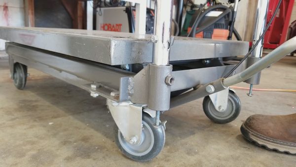
Now, I could make the lower hinge part longer (either by remaking it, or attaching a piece to the bottom), but that would defeat the purpose of having the handle slide down into the base in the upright position. After some thought, a better idea occurred to me. I can simply let the hinge bottom slide up and down, and add a retaining bolt to the bottom to keep it from pulling all the way out.
I then drilled holes through the bottom of the mounting pockets in the cart. The bolts slide up and down in this hole, allowing the hinge to move vertically, but still retaining them in the cart. This is important because, for example, to lift the cart up stairs or on to a ramp, you need to be able to lift up on the cart with the handle.
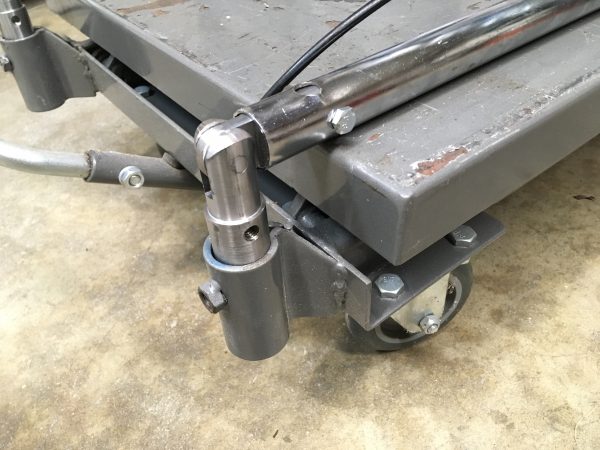
With this addition, I’ve now finally achieved what I wanted with this cart. The handle folds flat for storage, folds backwards for use as a pinball lift, and locks vertically for use as a work surface or general purpose cart.
I have a list of improvements I would make if I were to do this over again:
1) The top half of the hinge should be longer, with a longer slot to allow more handle travel in the upright and locked position.
2) The bottom half should be longer, to allow it to seat in the bottom pocket, but with a shorter shoulder so the handle can still slide down over it.
3) The mounting hole in the bottom should be rotated 90º and be unthreaded, since the cart’s handle pockets have a threaded hole already that could have been reused.
Overall though, despite all the flaws, I’m happy I was able to adapt what I made to solve the problem to my satisfaction. Sure, if I had infinite time, I might remake it with the above improvements to achieve the original vision, but I have other things to make. Onward!
Hey Quinn –
Nice mod. I have the same cart, but I’ve found a ton of uses for it. Mainly I use it as a platform for working on power equipment, like lawnmowers and snowblowers. Got sick of working on those things on the garage floor, so I took this lift (20% off coupon FTW!) and fitted a larger diamond plate top to it. My local steel supplier had surplus diamond plate, so I welded some angle iron to the bottom of it that just fits the stock platform and added a hitch pin to keep them together. Now I can easily get power equipment up to waist level, and I can get right up close and personal with repairs.
One problem, though – the hydraulic jack on mine leaked right from the start. Also came with no oil in it – should have been a red flag to me. Maybe I’ll go tear it apart right now and see where the problem is.
I’d be interested to hear back what you find the problem is. My money is on the o-rings. A common pattern is that cheap hydraulic shafts aren’t well finished, and the rough surface wears out the seals prematurely. Finishing surfaces well is expensive and the consequences aren’t seen for a while, so it’s a classic cost-cutting measure in cheap tools.
Sweet project. The Patreon videos were the best part. There’s just something entertaining about watching chips be made.
Thanks! Honestly, that’s why I expanded into video. Machining is such a motion/visual medium that pictures don’t just don’t it justice.
Thanks for another great write up Quinn.
I totally understand about the hesitation of buying a very specific tool that you worry will never be used again and just take up valuable space. Believe it or not, my equivalent tool was a 2nd hand, industrial, pedestal drill-press. In hindsight it is obvious that I’d use it a lot, but at the time I didn’t foresee how much I’d use it and was only focused on how much of my limited floor space it’d consume.