Sometimes a simple repair gets all kinds of weird.
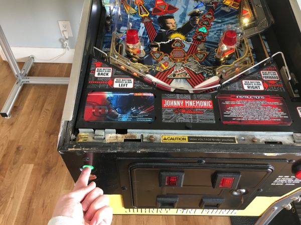
A couple of months ago, a good friend was over and wanted to play some pinball. “Great,” I said, “I have a pinball machine. Right this way”. What- that doesn’t happen to you? Not important. Anyway, she fired up the machine, pressed Start, and…. nothing. The machine did not acknowledge that the Start button was being pushed, despite the rest of the machine being in apparently perfect working order.
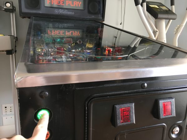
I left it at that for the time being, knowing in the back of my mind that the microswitch on the button had no doubt failed. Those things fail all the time, and it would be an easy repair when the time came. Well, today the time came, and it was not an easy repair. It’s a good story though, so let’s proceed.
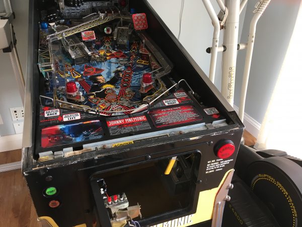
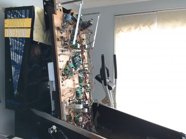
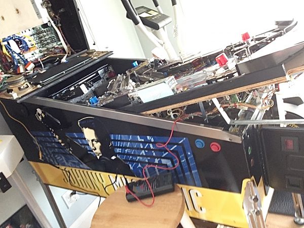
Put yourself in the mind of me six hours ago, when I started this. Convinced it was the switch, I proceeded to dismantle the machine far enough to reach it (which luckily is not far at all).
The next step is to remove the balls. This is very important because if you lift the playfield with the balls still in it, they are likely to come crashing down on who-knows-what and break things. I’m a little rusty at working on pinball machines (frankly Johnny has been darned reliable lately) and I’ll admit here that I forgot to remove the balls this time. Luckily all that got broken was my pride. Sprocket also jumped out of her skin at the noise, so that was a mess to clean up.
Let’s go back to pretending I didn’t make the single biggest mistake you can make servicing a pinball machine, and remove the balls first.

At this point the playfield lifts up. The one trick to be aware of with Williams machines is that you have to pull the playfield all the way forward before lifting it. The hinge has two positions, and if you don’t do this right, the playfield will slide back into the cabinet while you’re lifting it, which is really horrible and bound to damage things. I always lift carefully, making sure the hinge is locked and the playfield won’t slide backward as it goes up.
Okay, at this point we’re still blissfully naïve and pursuing the Switch Hypothesis. Let’s get back to that.
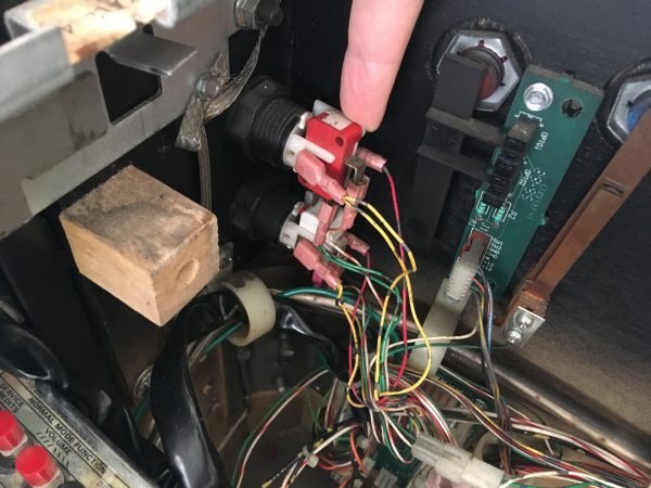
These microswitches are simultaneously way overrated for their job, and woefully inadequate. They are overrated in that they are typically 120V switches with current capacity somewhere around an amp. They are the same switches you find all over the place in appliances, power tools, garage door openers, and pretty much anything else large and electrical in nature. In this application, they are only switching a 5V logic signal from the CPU. However, they need to stand up to many years of abuse by teenagers, and thus why such heavy switches are used. The problem is, they tend to see way more cycles than microswitches are really good for, and as such wear out fairly quickly. They are also very susceptible to internal corrosion, and unlike leaf switches (the predecessor of the microswitch in arcade and pinball machines), they cannot be serviced. This is a microcosm of the repairability debate that you see in many spheres. Is it better to have cheap things that are easy to replace but don’t last long, or expensive things that last long and can be maintained, but require said maintenance?
Philosophy aside, the good news is that these switches are very easy to inspect and replace.
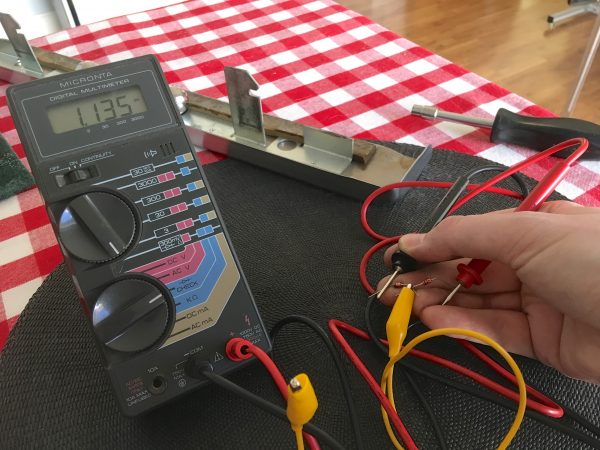
The next logical step was to test the switch. Time for ye olde multimeter (not a figure of speech- my Micronta is almost 40 years old).
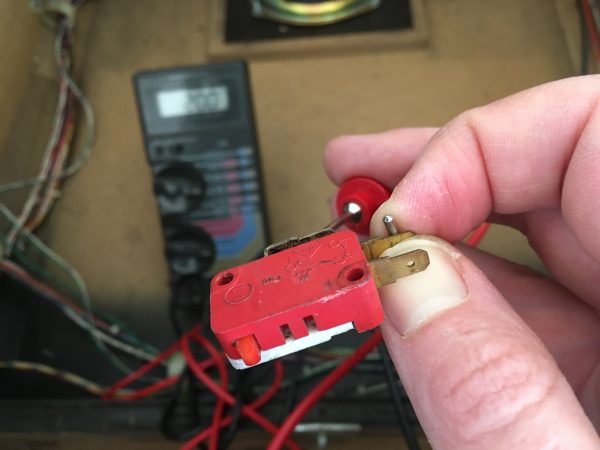
Sometimes a piece of evidence can lead you astray. Perhaps there were multiple problems here, but more likely this switch, while suspicious, was fine. However, because of the slightly flaky behavior, my mistaken hypothesis seemed to be confirmed and I confidently pressed on down the wrong path. I usually have a few of these switches kicking around, so I dug through the junk pile.
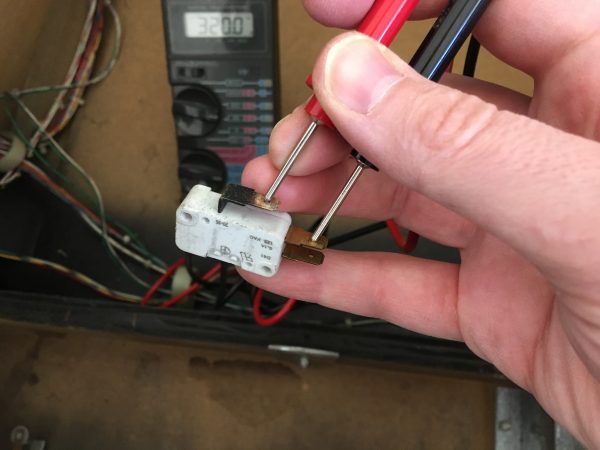
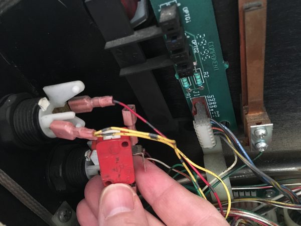
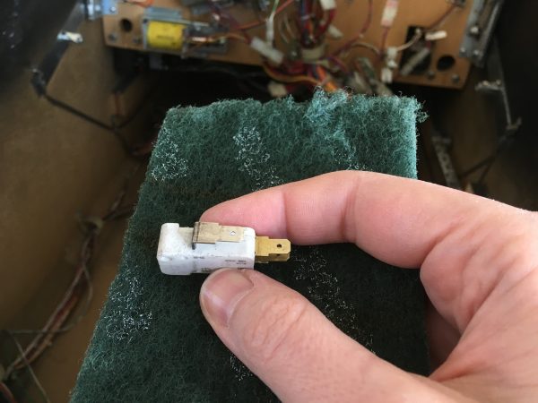
I cleaned up the contacts on my “new” switch with some scotch-brite, and installed it.
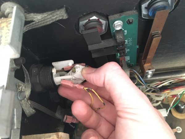
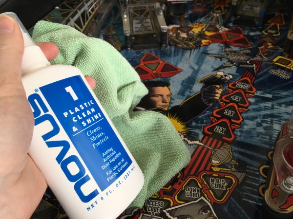
At this point, I was so confident I had fixed it that I grabbed the Novus and polished up the playfield before reassembly.
All that was left was to push the Start button and revel in victory. I can’t wait for all these chickens that I have here in egg form. There are so many of them!
Well, now things get interesting. Keeping our wits about us, we must remember the basic technique of debugging any complex system. Start close to the problem, and work your way upstream. Every link in the chain is guilty until proven innocent (just like social media).
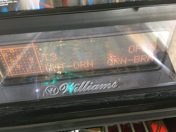
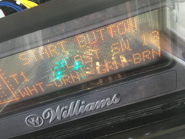
With the switch test mode still active, I started working my way upstream from the problem. You can set it up so the machine beeps when the button you are looking for is detected. That allows you to go about your debugging with the playfield up and the screen not visible. Those Williams engineers knew what they were doing. These machines are built for serviceability! It’s easy to forget what serviceability actually looks like in this day and age.
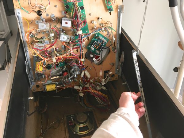
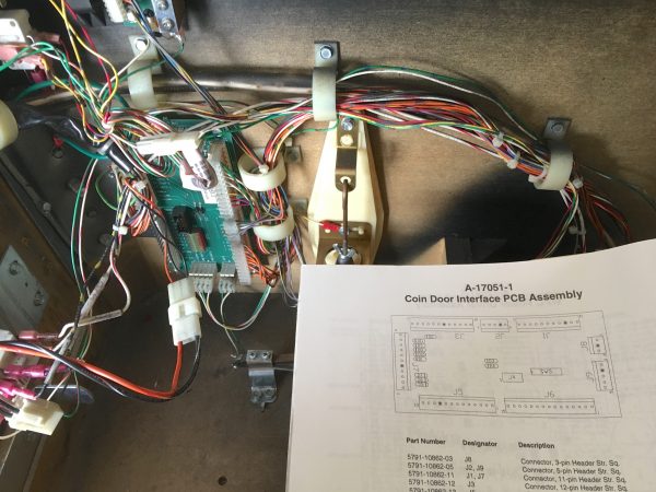
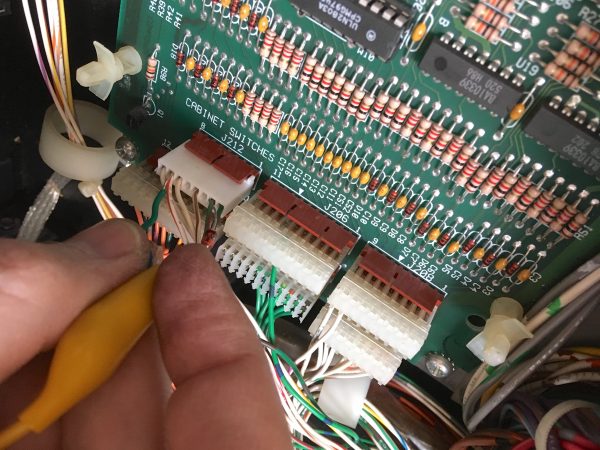
Following the wires back from the switch, their next stop is the Coin Door Control Board- an outboard PCB that collects all the inputs from the front of the machine and forwards them back to the main CPU board. It includes flipper buttons, coin mechanisms, tilt bob, slam switch (see: teenagers), and so on.
Let’s take a look at that board and see what we can learn.
Having ruled out the switch, the next suspect is the wires running to the PCB. A quick continuity check verified they were fine, so now we look at that connector. An easy test there is to measure continuity from the far end of the wire to the pads on the PCB. If that works, we know the connector is okay. That all checked out, so let’s look at the PCB itself.
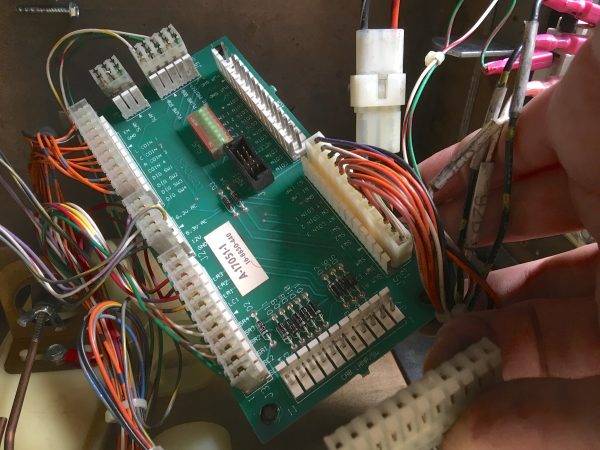
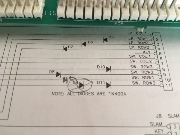
The coin door PCB is actually very simple. It’s just a bunch of connectors and some diodes. You might think that pinball machines simply run all their switches back to the CPU, which decides how to act on them. However, there are way too many switches to do that. No CPU or microcontroller (especially from the 1980s and 1990s) has enough inputs for all these switches. Instead, they are arranged in a matrix, just like a keyboard. Each switch is at the intersection of a row and column wire, and has a diode to separate it from the others in the matrix. The CPU scans the matrix by quickly running through the columns and rows, looking for a closed circuit. This is an efficient design, but it has a couple of key flaws:
1) The scanning takes time, and things happen very fast in a pinball game. A common bug is for switches to get missed if they are physically close together on the playfield and the ball is moving very fast. A design technique to get around this is to group switches that are physically close together into the same row/column (depending on scan order) on the matrix, to make sure they get scanned in quick succession.
2) The matrix relies on diodes to keep the switches distinct, and if any diode goes bad in a row or column, all sorts of weird things start happening to other switches in that row or column.
Now that we’ve ruled out downstream physical switches, wires, and connectors being the problem, we have to turn our eye to the matrix diodes. That’s what we’ll check next. For that, we need the schematic.
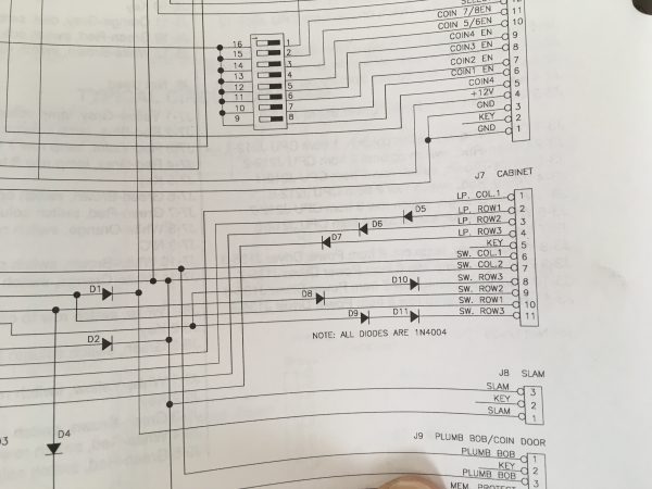
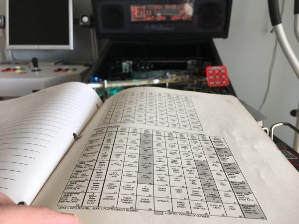
The Start button is pin 11 on that connector, which oddly has two diodes in series on it. That’s very unusual, and I struggled to grok why that might be. However, we can start by testing all the diodes. These are quite often the issue with switch problems, so it wouldn’t surprise me. Before busting out the meter, there’s a simple test you can do. If there’s a bad diode somewhere, as I said earlier, it will cause problems in other switches as well. So a good trick is to test all the switches in the same column and row as your bad one. This is such a common procedure that the manual has the switch matrix on the back cover.
Normally, a bad diode will take out all the switches in the same row or column. In this case, I had two other switches in my column that were bad, but not all of them. That’s odd! The Launch button and the tilt bob were not registering. The plot thickens!
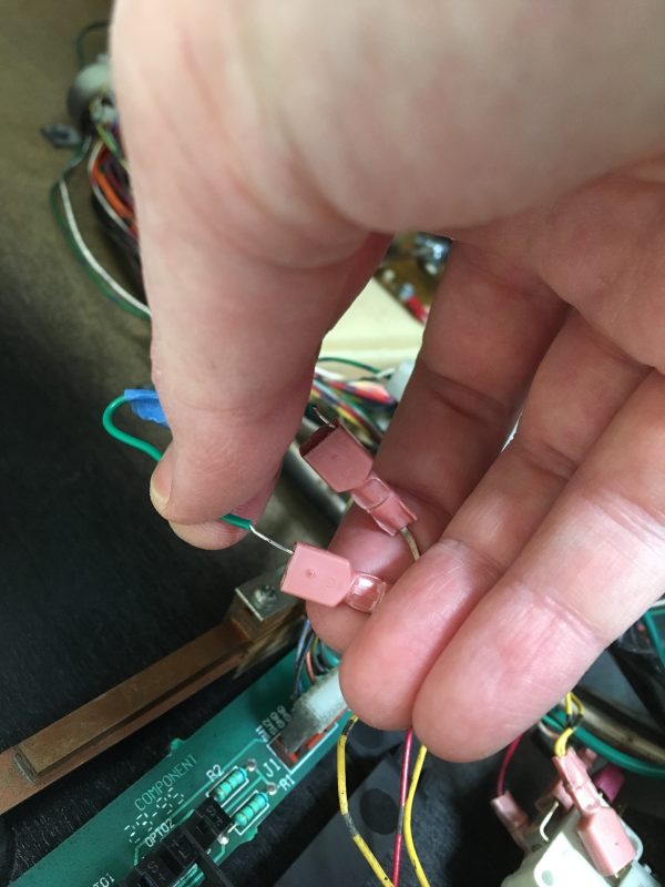
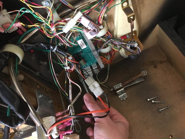
It’s not clear yet what’s wrong, but I had enough evidence to start suspecting diodes, so I decided to pull the coin door PCB and get busy.
Before I get to the diodes, I thought one more test of the connector might be in order. It was worth a shot to try shorting pins on the connector to see if the game would register the buttons.
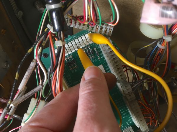
With the PCB out on the table, I could get out the diode tester and go to town. This brings up a perennial question- can you test diodes in circuit? The answer is… sometimes. If the circuit is simple enough that you can anticipate the side effects, then yes. If you’re not sure, best to desolder one leg an eliminate variables. In this case, I opted to test in circuit because this board is extremely trivial. It’s literally just a few diodes spanning some connectors.
All the diodes checked out fine, annoyingly. However, there was one thing niggling at me…. that double diode on the pin with the bad button. Why two diodes? I tried measuring the voltage drop (using the diode mode on the meter) across where my switch goes, and it reads as though it is one diode. That makes no sense, because there are two in series. It should show twice the voltage drop on the diode tester. Something wasn’t adding up.
This really seemed to suggest one of those series diodes was shorted, hence registering as one diode. Why are two needed? I don’t know, but if one is bad, that might be the problem. However, I tested all the diodes individually and found them to be fine. Then I tested the two series diodes together, and got… no connection. What? How?
That’s when I threw out all my assumptions, and used the meter to trace out this board. This wasn’t adding up. You know what I found? The goram schematic is wrong, that’s what.
So with The Great Diode mystery figured out, I had learned… well… nothing, really. I had an awesome feeling of cracking a code, yet I was actually back at square one with the problem. I kept coming back to the fact that the tilt bob and launch button were also dead though. That was a suspicious coincidence. If not a diode problem, what else do those three switches have in common? Studying the schematic revealed two of them are next to each other in the J7 connector, which is suspicious, but the launch button has its own connector. So probably not a connector issue. I considered re-pinning those connectors, but that’s a lot of work and the evidence just wasn’t pointing in that direction.
I spent a bit more time in the mental trap that it had to be the coin door PCB that was the problem, because all the failed buttons connected to it. That was the only pattern I had so far, which made it compelling. It took some time to get me to start thinking laterally again, at which point I realized I needed to resume going upstream. Like it or not, I had logically eliminated everything back to this point. The next upstream place was the harness carrying the signals from the coin door board back to the CPU board.
The next reasonable step was to continuity-test that harness. That would let me check the connectors at both ends and all the wiring in between.
This meant digging back into the schematics, because there isn’t one nice harness that goes from the coin door PCB to the CPU. Those wires split off on their way back and end up in all manner of crazy places. Each wire potentially ends up somewhere unique. Or does it? More on that in a moment. Back to continuity checking wires…
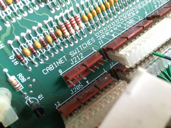
At this point the investigation led inexorably back to the CPU board. This was not great news, as I was not looking forward to pulling that. My simple Saturday morning repair was turning into a big job. Nevertheless, I was making progress, so I pressed on. Remember how I couldn’t find what the three bad switches (tilt bob, launch button, start button) had in common? Well, tracing that coin door harness back to the CPU answered my question. Those three switches all wind up on the same connector on the CPU board! J212!
Immediately, I knew something was afoot. That connector has been replaced before, by me, on this very blog. I had completely forgotten! My next thought was that perhaps my repair had failed and this connector had gone bad. Before jumping to that, there’s one more thing I can try. At this point in the system, you can’t short pins together to simulate switches. You’ll activate whole rows and columns and generally make the CPU unhappy. However, you can bridge pins with a diode to fake the switch matrix into seeing your button.
The next upstream point past this connector was the header on the CPU board. A long time ago I moved the batteries outboard because they had leaked on this very connector. You see where this is going.
I pulled the connector to have a look at it, and it seemed fine. However…
Back when I replaced that connector to eliminate the corrosion, I recall thinking that ideally I should replace the header as well. The thing about alkaline battery corrosion is that it’s basically electrical cancer. It never goes away unless you cut out everything in a six foot radius around it. Okay that metaphor got really weird there, but you get my point. At the time, I figured these pins might re-corrode if left in place, but I made the calculation to save time by cleaning them and addressing it properly later if they act up. It’s later, and they have acted up. So what am I going to do? Clean them again and address them later. Time happens to be short today so I can’t get let this project feature-creep to the point of pulling that CPU board and doing surgery on it. That will have to be a project for another day. I cleaned up the pins with a nail file and some emery paper, and reassembled everything. Did it work? You can probably guess the answer by looking at your scroll bar on this article, but…
Well, that was a damn satisfying bit of debugging, in the end. I still intend to replace that header, but in the meantime Johnny is back on the line and ready to entertain my guests (for free if I like you).
Nice article.
WRT pulling out the glass, it’s quite robust, generally. I had a bad cats with glass that would slide out on its own when you pulled the lockdown bar. It would have stopped on its own, but I wasn’t thinking and so I stopped it with the lockdown bar. The sharp edge of the lockdown bar. BAM! It’s hugely impressive how loud it is, and an incredible PITA to clean up.
My wife got the experience when we were moving a shower enclosure. She had a panel, set it down on the tile (mistake #1) and then twisted it. BAM. I heard it from downstairs at the other end of the house.
Yikes! I’ve seen/read a few horror stories on Pinside about broken glass, and finding the little cubes in the dark corners of the cabinet for years afterwards.
HA HA HA!
“You can probably guess the answer by looking at your scroll bar on this article.”
Amazing. Great writing as always.
Aww, thanks! 😀
Excellent debugging! Is there anything that can be done about alkaline corrosion other than replacing parts? Some sort of cleaner?
The best thing I’ve found to clean it up with is vinegar (a mild acid neutralizes it). However it’s pretty impossible to completely get rid of it. It seems to always come back eventually. Sometimes it takes weeks, sometimes it takes years, depending on how well you clean it up.
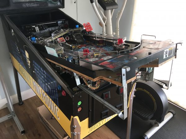
For a reason unknown to even me, I am amused that the pinball machine is right next to the exercise bike.
Fun fact- on the other side of the pinball machine is the MAME machine. All three of these have been featured multiple times on this blog. 😀