All your smartphone are belong to us.
This post has an exclusive companion video, engineering drawings, and 3D model for Patrons. Sign up now to see it! It shows detailed machining steps for this entire project.
This time on Blondihacks, we have a great milling machine starter project. In fact, this project can be done entirely on the mill, with only one lathe step (which is optional).
As you may be aware, I’ve been shooting a lot of video lately, both for my new Blondihacks YouTube channel, and also for my exclusive Patreon feed (both of which you should subscribe to). I’m not using a lot of fancy gear for this. For cameras, I’m using salvaged and borrowed cellphones of various flavors. Salvagers can’t be picky, so I’m using a mix of old iPhones, Samsungs, and Google devices. I also move these cameras around a lot and switch them out often. It quickly became apparent that I needed a very fast-to-set-up smartphone holder for tripods and camera arms that would work for any smartphone (or similarly-shaped device). You can buy such things of course (because you can buy everything), but I wanted to make what I felt would be the perfect solution for me. Here’s what I came up with.
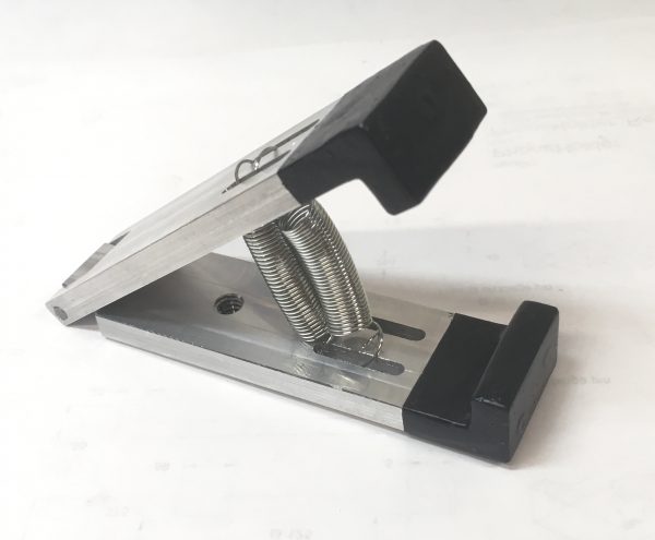
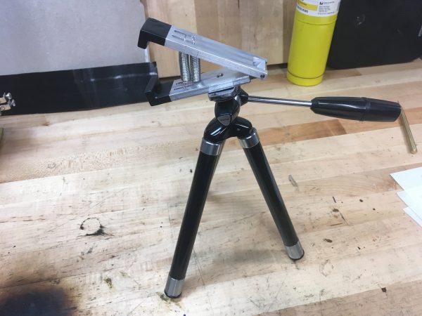
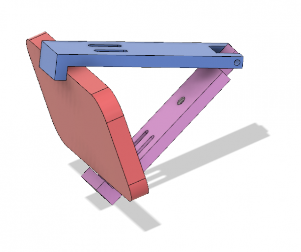
It’s (I think) an unconventional design, but it works (I think) very well. Switching out the phone is a quick one-handed operation, and it works with any style of case or phone or phone-in-case or whatever. You can shoot portrait or landscape, using front or back cameras in any orientation. Let’s take a look at a few examples.
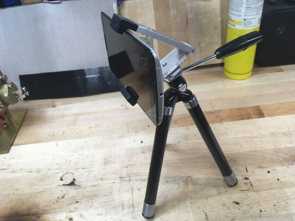
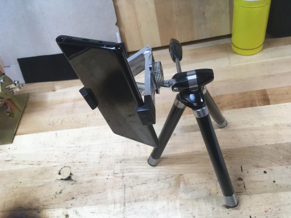
I also use it with two different iPhones that have different cases on them, and it’s all unicorns and puppies there as well. The design trick that makes it work is the angle of the arms. They support the phone in a universal way that presses it forward against the jaws securely.
I started by modeling this in Fusion 360, to get that critical jaw angle just right.
Detailed drawings and build instructions for this project will be posted to my Patreon feed. Sign up now to see them! This is a really great starter project for a vertical mill, so if you’re a budding machinist, give this one a try.
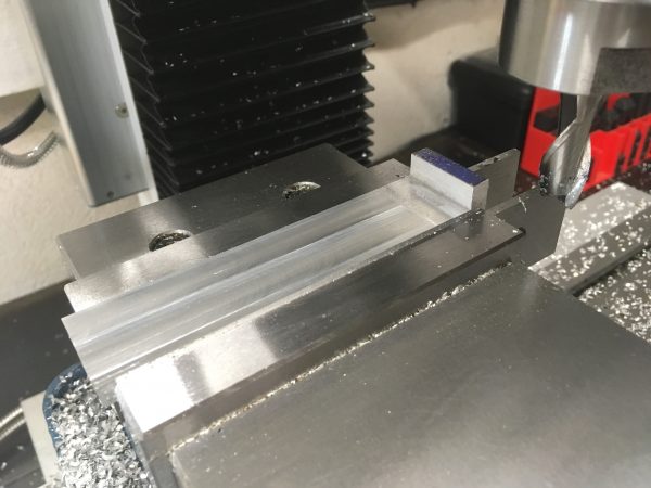
I’m using aluminum here for light weight and a nice look, but you could also make this from brass, steel, plastic, or candy cane bar stock. I suppose you could even use wood if you’re desperate. I’m using bandsawed chunks of 1″ bar stock, and the parts are 1″ wide. That means two sides of each part will remain unmachined, with the factory surface along the 1″ dimension. This will save a lot of work. The finish on the surfaces isn’t that critical here, so this is all fine.
I made heavy use of the DRO (digital readout) on my mill for this project. If you’re not familiar with DROs, allow me to explain them a bit. Traditionally, machine tools use graduated dials on the hand wheels to measure distance traveled. The travel of the slide is inferred from counting rotations of the dial. This works very well as long as you’re always moving in the same direction. Leadscrews (which move tables and tools on machine tools) are exceptionally precise, so with the right type of graduations, a simple hand wheel can easily achieve a few ten-thousandths of precision. So what’s the problem? Backlash. All mechanical systems have backlash, and leadscrews are no different. Backlash exists because a nut riding on a leadscrew has to have clearance from the threads in order for it to be able to move. Otherwise it would be a press-fit, effectively. This is where the physics of the real world mock our designs and drawings. This clearance is fine, because normally the nut is riding on one side of its threads, so the motion remains precise. However, when you change directions, the nut needs to switch to riding on the other side of its threads, and you encounter that clearance. That clearance in the threads has to be taken up before motion starts back in the other direction. Even if that clearance is extremely tiny, it still renders your hand wheel graduations meaningless as soon as you change direction.
Traditional manual machining uses some basic techniques to overcome this. Any time you change direction, you need to overshoot your goal by (say) a quarter turn of the hand wheel and then come back in from your desired direction. As long as you’re out of the backlash zone by the time you need the hand wheel dials to be reading properly, you’re fine. This was good enough for a hundred years or so, but technology has given us an easier way. The DRO.
A DRO is basically a way to have hand wheels free of backlash. DROs work by monitoring the position of the table (or carriage) directly, rather than inferring the position based on turns of the leadscrew. These measurements are generally made by an optical reader on a glass scale, so they are extremely precise and fairly immune to changes in temperature or humidity. Once you have a zero-backlash way to measure motion, it unlocks a whole new world of absolute coordinate systems. You can now locate one corner of your part, zero the DRO, and then move within a global coordinate system on your part with reckless abandon. You can always get back to anywhere you need to be, and you can do things like measure distances or make relative offsets from one feature to another. Furthermore, you now have a simple computer in the loop, and it can do math for you. This includes things like laying out bolt circles, finding centers, creating repeating patterns, or laying out curves. This is all immensely powerful, and no fancy CNC is required.
Since I said “CNC”, I’ll head off the comments now by pointing out there are alternatives to leadscrews which all but eliminate backlash. The most common of these is the ballscrew. Ballscrews are basically immune to backlash because they replace the sliding action of a traditional nut with the rolling action of a ball bearing. The “nut” contains a spiral-shaped chain of ball bearings, which means everything can always be touching. This allows you to preload it in both directions, and thus there are no clearances, and thus no backlash. Ballscrews are as cool as they are expensive, but lots of people do upgrade traditional manual machine tools with them. The ballscrew is basically what makes CNC machining possible, because it is both zero backlash and capable of driving heavy loads (unlike the toothed belts used by lightweight CNC tools like 3D printers, vinyl cutters, and laser cutters). There are other options as well, such as roller nuts. Eliminating backlash has been a human quest for a good long while. Though many exotic mechanical attempts have been made, the DRO does it with simple data.
Okay, with DRO 101 out of the way, let’s get back to our project.
Edge finders and DROs are a marriage made in heaven. When the edge finder is spinning, the tip flops around randomly. You move the workpiece up to it slowly until the tip centers itself (by touching the part), and then is kicked slightly to one side. You now know the surface of the work is in the same physical place as the surface of the edge finder was (which is why it kicked over). The tip of the edge finder is very precisely sized (usually to 200 thousandths), so all you have to do is move the workpiece another 100 thou in that direction and zero out that axis on the DRO. You now know the center line of the spindle is on the exact edge of your part. Super cool!
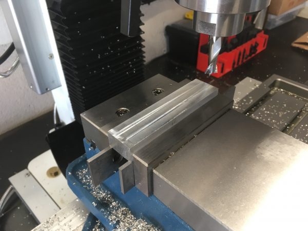
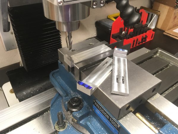
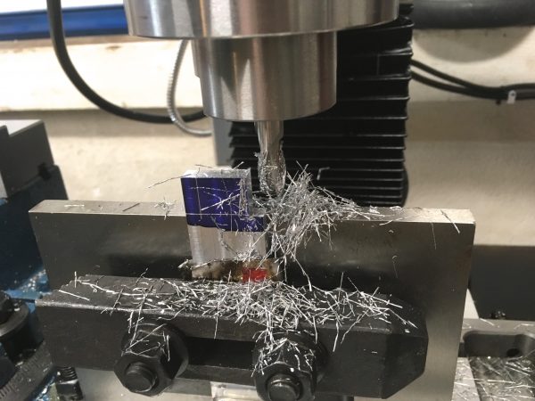
Back to our part. The first task on the phone holder is to make the overall L-shape by removing most of the top surface. This was done with a ½” end mill at first, and later a 2″ shell mill. I’m using all two-flute end mills here, which are a good choice for materials like aluminum which make gummier chips (compared to steel, where I would use a four-flute tool). Two-flute mills leave more room for gummy chips to escape, instead of piling up in the cut.
To make the final pass and clean up the inside edge of the L, I used to the DRO to position myself 500 thou plus half the diameter of the end mill from the end of the part.
As I keep saying, if you’re looking for a starter project for vertical milling, this is the one for you. The whole project is a series of simple flat dimensioning operations, and there’s a lot of chips to make, so you’ll get a ton of opportunities to experiment with feeds and speeds. It’s great for building experience with hitting dimensions on your particular machine. It’s also a great starter project because almost none of the dimensions are very critical. Except for the hinge area, a few thousands either way won’t matter at all for any dimension on the part.
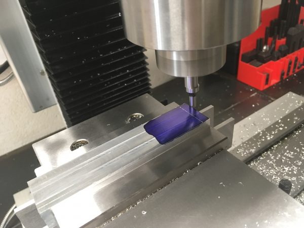
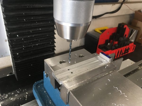
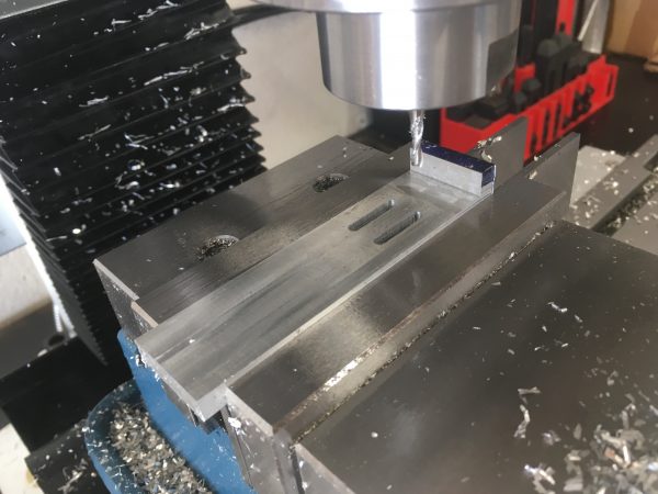
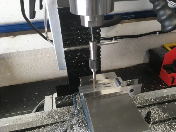
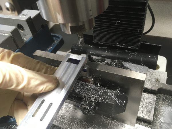
The next task is to cut the slots which hold the springs. Slot cutting is one of those operations that is extremely challenging to do using any other tools, and extremely trivial to do with a vertical mill. The results are super satisfying.
End mills aren’t generally good at plunging into material. You can do it, and there are end mills intended for this purpose, but in general I try to avoid it. Something I like to do where possible is to drill a hole at each end of the slot, a bit smaller than the final end mill diameter will be. This gives me a “plunge zone” at each end where I can deepen the cut without the end mill doing much plunging work. The center area is clear, and the end mill is just enlarging the hole as it plunges, and then resumes sideways cutting for the next pass to the other end of the slot.
I try to always show my mistakes on this blog, because that’s where the most learning (and humility) comes from. Every project I do has at least few mistakes, and this is no different.
Sometimes a part is still usable after mistakes like these, but I often choose to remake it just for the experience. Time is rarely of the essence on these projects (this blog/YouTube channel isn’t my day job, yet- psssst) so I usually chalk it up to experience and do it again. I learn something every time I make a part, so it’s never wasted time.
We need two of these basic arm pieces for the smartphone holder, so I immediately made a second one the same way.
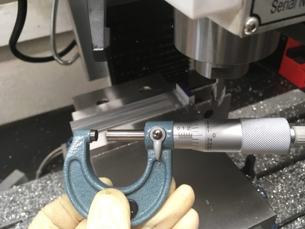
The last feature we need to make is the hinge that joins the parts. This was calculated in Fusion 360 to leave enough clearance to close tightly on the smallest device I could find (the Galaxy Note 8 and iPhone 5 without a case, width-wise).
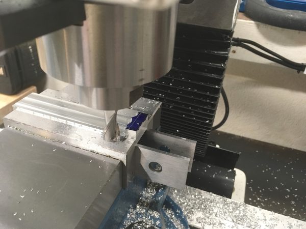
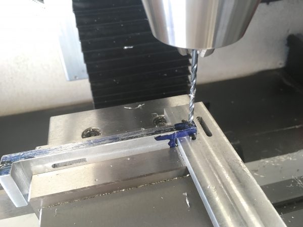
I needed square inside corners for my hinge, so it was going to need to be machined upright. This will be an interesting setup!
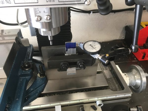
The part is clamped to a 90° angle plate, then I used a dial test indicator to get it precisely vertical. I found the edges with an edge finder, then started milling away the inside of my hinge.
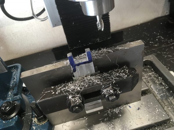
These hinge profiles need to be fairly precise in order to get a nicely-behaving hinge. I left five thousandths of clearance on each side for smooth motion with no rattling or sliding.
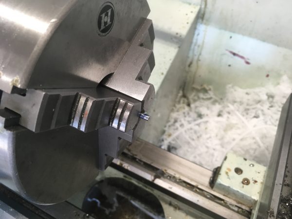
Our pieces fit together in much the way hinges do, so we’re most of the way there now. The last piece is a hinge pin. This is made with a piece of ⅛” drill rod. Drill rod is great for this sort of thing because it’s already precision ground to a precise dimension, and it’s tool steel.
The next operation is to cross-drill the hinge pieces for the rod, in a way that secures the pin and provides the hinging action. There are two ways to do this. If you have the tooling, an elegant method is to drill & ream the outer “fork” portion of the hinge to a half-thousandth undersize. Drill/ream the center portion on size for the drill rod. This way, the pin will press lightly into the outer piece, holding the hinge together, while the inner piece moves freely.
I don’t have a full set of over/under reamers (maybe someday) so I used the inelegant low budget method- I drilled all the holes on size, and retained the pin in one end with Loctite 603.
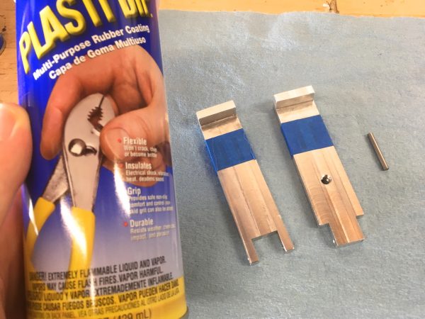
There’s one last step to do on this project, and it’s a very important one. Because this clamp squeezes the phone on two sides, it relies a lot on friction to hold it securely. This is especially true in a portrait orientation. Bare aluminum is not going to give us the friction we need. Some sort of rubberizing would be ideal, and luckily there is a delightful product for exactly this purpose. It’s called Plastidip. It’s quite an old product (invented in 1972) but it has recently become a darling of car customizers. It acts a lot like paint, but it can be removed with no damage at any time. In my case, the desirable property is that it leaves a thick rubber coating on anything you want.
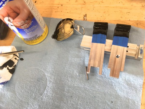
One trick I’ve learned with this stuff is you need to plan how you’re going to hang the part to dry. It will run a bit and leave a drip because there’s really no way to do thin coats with it. Plan ahead and think about where you want that drip to end up, then arrange to hang your part in the orientation that will do so when gravity does what gravity does.
With any product comes some learning curve, and Plastidip is no different. The instructions talk a lot about getting the “dipping speed” juuuust right, and it’s clear that’s a factor. The thickness and evenness of the coat definitely hinges on getting a smooth, consistent dip of the right velocity. That said, it’s ultimately pretty forgiving because it seems to cure well no matter what you do. The one mistake I made is trying to mask it like paint. That doesn’t work, because it molds solidly over the tape, and won’t sever on that mask line like paint does.
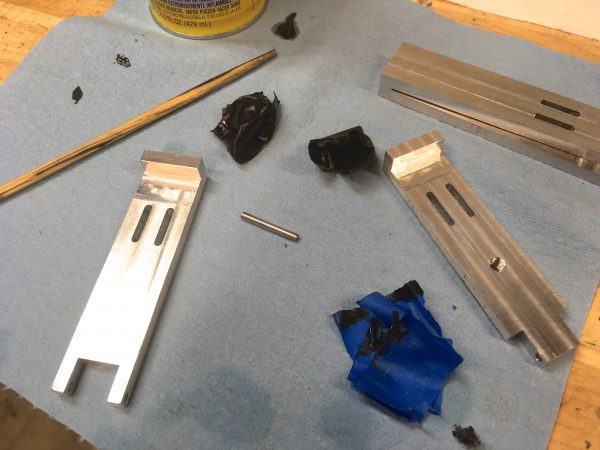
Rather than masking, what worked was to dip my part with no regard for the limits I wanted, then trimming it with a razor blade after curing.
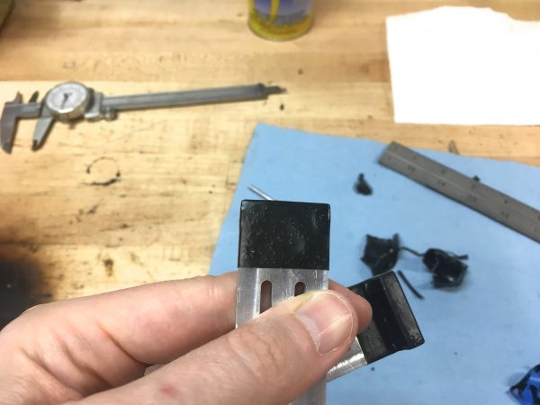
The good news is that Plastidip did exactly what I hoped it would in the end. It provides a soft grippy surface that holds the smartphones securely!
With the arms complete, all that was left was to insert the hinge pin, and hook up some springs. The slots provide plenty of room to experiment with multiple springs, or springs of different types, so I played around until I found a combination that was easy to open, but still held the smartphones securely.
This device has turned out to be so effective and useful for shooting video around the shop that I built a second one. I keep finding more uses for these guys! In addition to tripod use, you can attach it to a magnetic-base arm such as a Noga. I’ve mounted steel plates around my machine tools to assist in filming and photography, and it’s easy to move the camera around to set up new shots.

Patrons can find video of building one of these in the exclusive Patreon feed, so sign up now to see that! Patrons also get the 3D model file and complete mechanical drawings if you’d like to make your own!
I can’t help but cringe to see you take 1″ stock and turn half of it into chips. Since you are covering the jaws in plastidip, wouldn’t it have been more efficient to start with 1/2″ stock, skip all the flat machining, then cut the L ends separately and bolt them on? Or were you just itching to try out the new mill? 🙂
The stock is 1” WIDE. I bandsawed it to just over the size I needed in the other dimension. I don’t know why you assume I “turned half of it into chips”.
Making it in two pieces would have been a lot more work and a lot more difficult. That’s a lot of fiddly little operations to make something that small that would have to be squared on six sides, have two holes center drilled, drilled, and tapped, etc. Machining the L is stronger and way less work.
> then I used a dial test indicator to get it precisely vertical. I found the edges with an edge finder
Would be good to see how this is done at some point. I presume you run the test indicator up and down the vertical edge until there’s no change from top to bottom?
Yep, that’s exactly right. This is the sort of little detail that motivated me to add video to Blondihacks, because it’s so much easier to show something like that than describe it in photos. I’ll be covering dial indicators and dial test indicators in upcoming YouTube content.
I got annoyed with indicating in the mill vise. What’s working reasonably well for me was making a u-shaped chunk of metal that is a tight sliding fit into the t-slots on the table, and clamping the vise to that, then bolting the vise down. It isn’t perfect, but it’s equal to or better than my mill’s straightness. (As in, I clamp a piece of glass in there and see the same amount of variation on the DTI, after indicating the vise, that I see when I clamp the vise down with a fixture and indicate the glass.)
I recently learned a great trick for indicating vises quickly. Put a parallel in the vise that is longer than the base. Then, zero the indicator when aligned with the left mounting bolt. Snug that bolt, then go to the other end. Now the indication process is 1D instead of 2D because the pivot point is zero. You can do it in one or two passes this way! Saves that whole “walking in” process that most people teach.