Time to get serious.
Well, Veronica is alive, and running code that we can put (very slowly) into memory. So far so good, but something has gotta give.
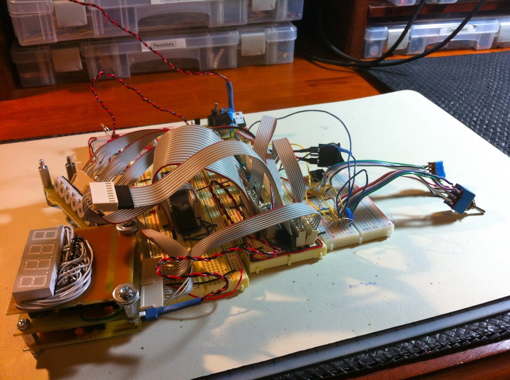
It’s time to starting making some of these bits (pardon the pun) solid, both so I can work on new interesting abilities for Veronica, and so I can have some damn breadboards back.
I spent a lot of time thinking about this, and planning out various strategies. I’ve settled on what’s called a Backplane Design. Essentially, every component of the machine is treated as a module that is plugged into a large master bus. Wikipedia has a nice treatment of this topic. Ideally, everything is completely general, so you could have multiple CPUs, multiple memory systems, or any other weird combination of components. In reality, that’s a lofty goal, and mine won’t be so fancy. This is in contrast to a motherboard design, where most major systems are on one large board, and you have a couple of connectors or slots for expansion in specific ways.
For me, the advantages of a Backplane design are:
- Modularity. Since I’m new at this computer design thing, and I’m definitely not an electrical engineer, it’s
likelyinevitable that I’m going to make a bunch of mistakes. A design like this lets me swap out pieces and rebuild them as I learn better ways to do things. - Size. By distributing the pieces over a bunch of smaller boards, they all fit into the size limits of the free version of Eagle. I also have practical limits on how big a PCB I can etch.
- Warm fuzzies. The modular nature appeals to my inner engineer. My primary area of expertise is in software, so this way of thinking comes very naturally.
- Ignorance. I have a weird habit of wanting to figure everything out myself, without reading up on how other people solved the same problem. It’s less efficient, but more fun this way. Thus, I chose this idea because I thought it sounded like a good way to do things, then found out later that there’s actually a name for it.
So, my next step for Veronica will be to take all the major systems that I laid out on the breadboard, and convert them to backplane modules. First, I’m going to need the backplane itself. This is a passive backplane design. I had originally designed an active one (where the backplane itself regulates communication between modules), but I simply ran out of physical space on the board. I had to move the bus control logic onto the module cards. Here’s the Eagle file, and the schematic:
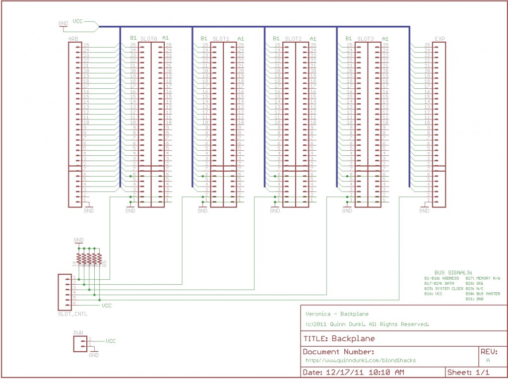
The slots are (old) standard IBM ISA connectors (two-sided, 31 pins per side). I’m using physical ISA connectors, but I have no idea how the ISA standard actually works. I’m making up my own bus system as I go along. Each slot has address lines, data lines, power, ground, and some control signals (labelled on the schematic, in the lower right). Of particular interest is the Bus Master pin. Each module must check this pin for permission to use the bus. All those pins are pulled low by default, and routed to a connector. Eventually, some sort of bus arbitration controller will be plugged in there. For now, I can just plug in some switches to get things going. I always try to do the bare minimum that will accomplish something, while allowing room for the future. It’s easy to get trapped in a cycle of analysis paralysis, trying to design the perfect system the first time through. Speaking of the future, there’s also a row of breakout pins at each end of the bus. These will allow for more slots to be added, and will also be great for debugging.
So, on to the PCB (and Eagle file):
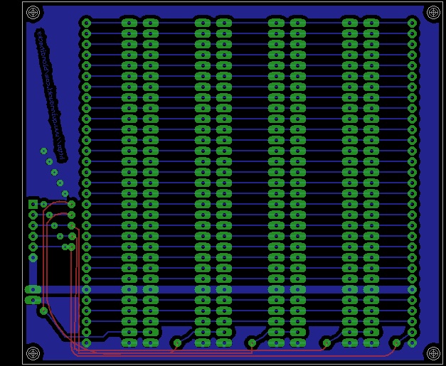
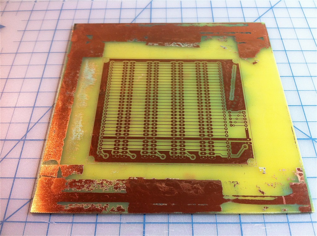
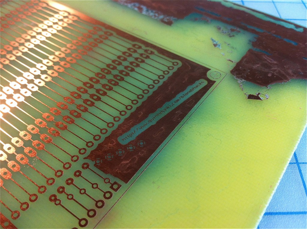
I etched this PCB using my usual technique.
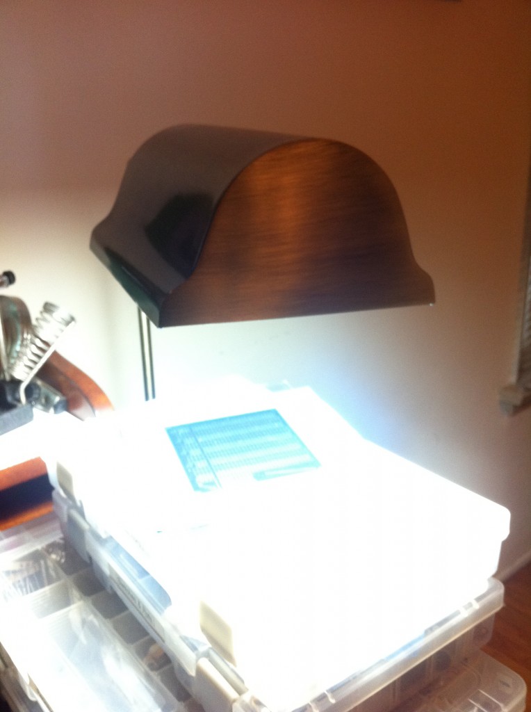
Even though the free version of Eagle limits you to about 100mm square, I wanted my backplane to be a little larger, for physical stability. I had the bright idea to simply mask off the extra real estate around my 100mm x 100mm mask, and center it on a 150mm x 150mm PCB. Well, that seemed like a bright idea, anyway.
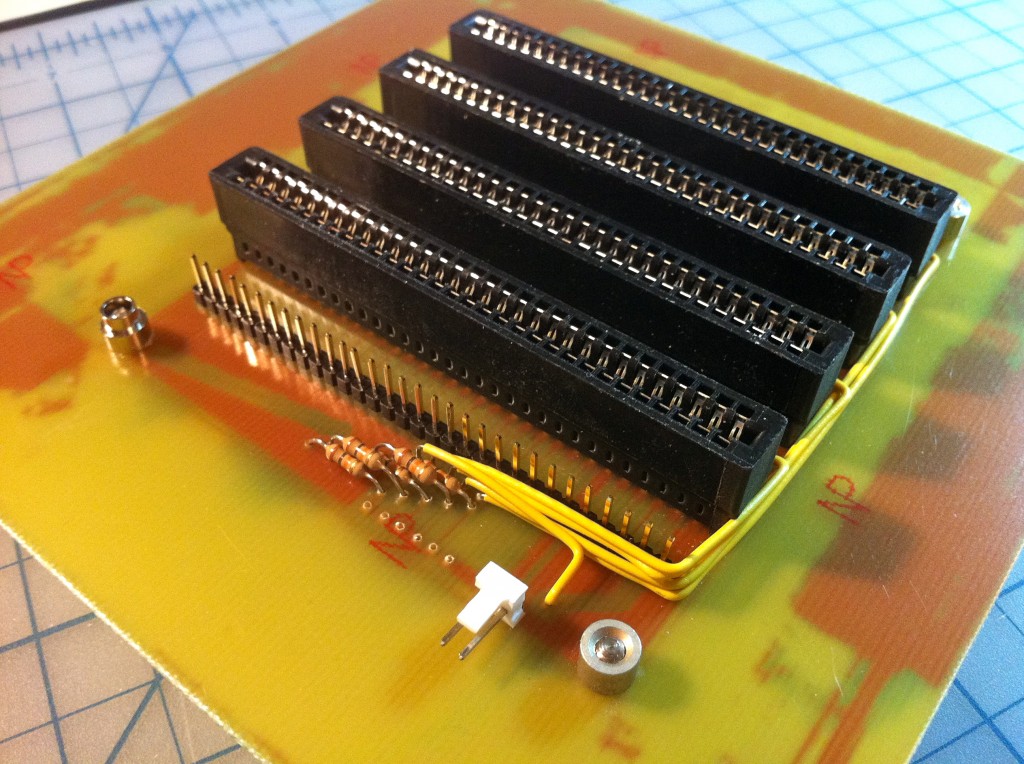
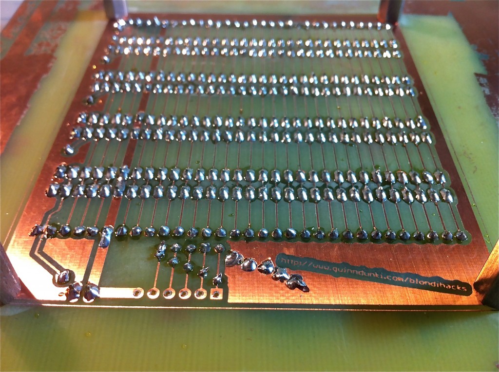
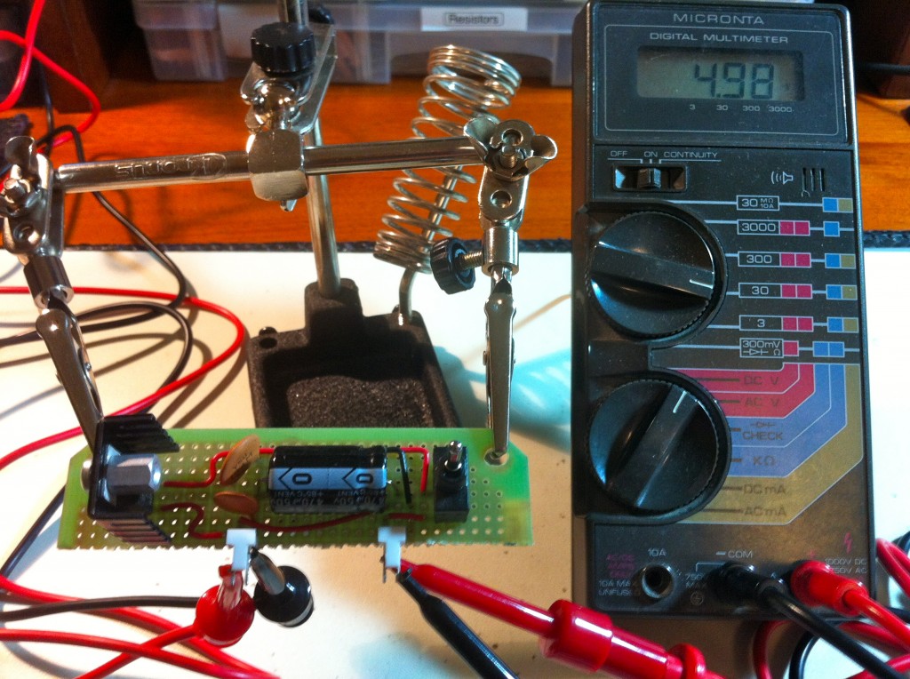
As sort of an after-thought, I decided to put a little power supply on the backplane as well. Until now, I’ve been using my Juice Bridge on the breadboard, but that will be inconvenient once I start developing modules on this backplane. Having its own power seems like a good idea. The design is the same as I used for Cardio Power.
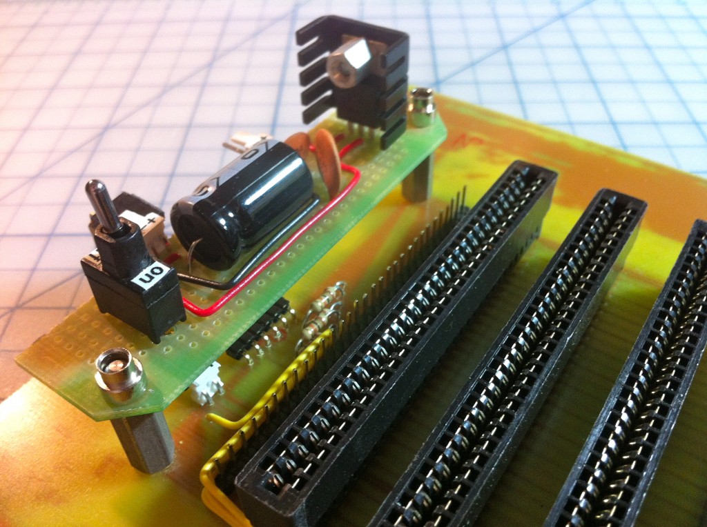
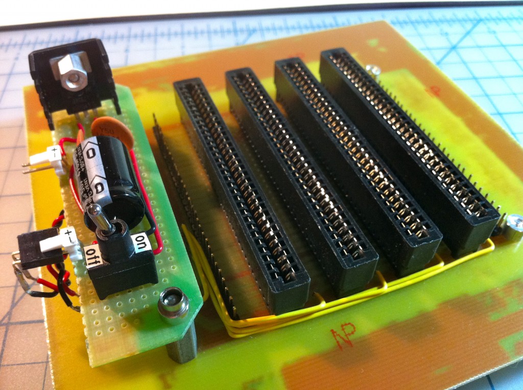
So, with the backplane out of the way, I can start making real parts for Veronica. Hooray!
Looks great!
I’m trying to decide which seems more mind-numbing… Drilling a zillion holes, or soldering a zillion pins.
Thanks! I find the soldering satisfying, and it even smells good, if that’s not too weird to admit. 😉
She is such a sexy device. I love it!
I know what you mean about the rats nest that quickly forms. I’m building an Apple 1 clone on a giant breadboard and even with well thought out placement, 16 address and 8 data wires into each component gets messy fast.
Needless to say, I’m watching Veronica’s development closely – I’ve already “stole” your 555 single-step circuit.
Cheers!
Very cool! If you have pictures or a link, do share. My first machine was an Apple //+, which I still have in storage somewhere. Regarding the clock circuit, I’ve made an improvement to it which I’ll be talking about in the next post. The clock needs to be held high when paused to prevent losing the internal register state on the 6502, and my new one does that. I believe there’s a better way to single-step using the SYNC and RDY lines, but I don’t know the details. The 6502 data sheet alludes to it but is light on specifics.
If you’re on G+, you can follow my escapades there: http://www.google.com/profiles/jeff.karpinski
If not, here’s a link to the most recent pic: http://i.imgur.com/VsEKS.jpg
My BoArduino based logic analyzer is similar to your HexOut, but it stores captured bytes in a 1024 byte ring buffer that can be recalled with buttons. I do want to build a better one with full 16-bit capture.
Great idea to use the ISA connectors! My own project will use 40-pin connectors (also easily available because you can take them off any old IDE ribbon cable), but I think I like this idea better!
Are you going to keep the pinout compatible with the ISA pinout? It should be easy to do, ISA is not very complicated, and that way you can reuse old PC hardware for peripherals.
I once did a project on my Amiga to connect a Western Digital ISA RLL controller to the 68000 processor (I got the schematics from a book or magazine but I would have been able to figure it out myself) and used the published PC/XT BIOS listings to write some 68000 code to make it work. It was impossible to boot the Amiga from the hard disk, because the driver had to be loaded from floppy (I didn’t have an EPROM burner) but I used it as my main Amiga storage device for a long time.
===Jac
Never mind, I see now that you connected both sides so you can’t make it ISA compatible…
Yah, it was a tough call, but I’d spent a lot of time routing that board (and the CPU board) already, and just wanted something to work so I could move on. I can always rebuild it later.
Meant to say- I had spent a lot of time routing it, then when I found out I couldn’t etch it with the fancier 62 pin layout, and had to redo it all, I just wanted the quickest workaround possible that would allow me to proceed.
That would be fun to be able to use old peripherals, but the limiting factor is that ISA requires double-sided PCBs. I’ve never etched those before, and I don’t want to bite off too much at once. I suspect I’ll need to do that at some point, because I’m kinda limited in what I can achieve with only 31 pins in the backplane bus.
PS. I <3 Amigas. I've never used or owned one, but I was always very jealous of them back in the day. 🙂
I reckon you can still consider using old peripherals even if you can only make single-sided PCB’s, even without destroying what you already have; all you need is a VeronicaBus-to-ISA converter board (single sided) that plugs into your backplane and has one ISA slot on it, connected according to the ISA specs. With one ISA slot you don’t have to route traces between the pins: your traces or jumper wires can go around the connector.
To interface with a hard disk controller or an I/O board (serial/parallel/game) you will only need a few address lines and some glue logic to convert R/!W and CLK2 from the 6502 to !IORD and !IOWR on the ISA board. My hardware didn’t use interrupts or DMA. If you can get your hands on an old MFM or RLL or IDE controller and hard disk, it will probably cost less than $10 in parts to connect it to your 6502 system. Making it work is a different story of course 🙂
===Jac
I see what you’re saying- cool idea! I’ll have to look into that. Also, “VeronicaBus”” made me laugh. It’s a standard of one! 🙂
A friend, Etienne Delacroix, has a large stock of backplanes which he made by getting old PC motherboards and sawing off the area with the ISA connectors. He uses them for his own designs so doesn’t worry about ISA compatibility except for keeping the ground and power pins the same when dealing with four layer boards (for the rarer two layer boards all the pins are more or less the same). The advantage is that he doesn’t have to etch the boards nor solder the connectors.
I like that! Up-cycling always makes me smile.
A side version of this, I just cheated by scounging out an old ‘desktop’ board. It has a single connector on the board, and a helpful 3-slot backplane that sits inside this. Job done!
Really cool stuff Q. Love seeing her come together. It is quite snazzy that you are actually etching the boards. The modular backplane does seem like your style.
@Jeff/3d0g – Looks great. We did a lot of digital work like this on large kits when I was in college. Wiring together computers and microcontrollers from chips and with wires. There were a lot of older guys and girls who had been through the courses and had much choice advice. If I can pass some along, definitely buy lots of different colored wire and have a schema for your colors. I can’t stress that enough. And anything you can do to speed up stripped that little cm off the end of each piece is worth it. Lay your wires down in right angles along the board rather than arcing up above the chips. That’s all. Keep up the great work!
Thanks Jon. I’ve been tinkering with electronics for a few decades now – even managed a 2nd place in Nuts & Volts annual design contest ’bout 10 years ago. 100% agreed on the color schema and anyone who works with breadboards learns the value of a Neiko stripper FAST!
I’ve never been a big fan of “make it pretty” breadboard wiring though. Granted, while not really a concern at 1MHz, longer runs can lead to tough to troubleshoot noise issues in some designs. This project will go through several builds, finding optimal chip placement, etc. before eventually making its way to a perma-proto of some kind for long-term reliability. That’s the point where it’ll get tidy.
Cheers!
nice ! i bought a 6502 from jameco about *mumble* years ago to play with, and it is still patiently waiting for me… i think you are right on with the backplane idea. you can break up the design problem into smaller chunks of free time (hard to come by for me these days), redo parts as you learn, and add extra capabilities later.
do you have a favorite source or vendor part# for the connectors?
also, i’ll be interested to hear your experience on what board thickness works well with the connector.
thanks for sharing !
I got the connectors from my favorite surplus shop, All Electronics. I love going to the brick and mortar store (it’s old school and fun to dig), but I believe they sell everything on their website as well, allelectronics.com.
I’m using the GC brand presensitized PCBs from Jameco, which I think only come in one thickness, though I can’t recall offhand what it is. I think they will work, but we’ll know for sure when I get the first board built.
I saw this the other day and… Well, I got a bit excited. Clean off living room table. Add.. My scope, function generator, scientific grade bench power supply, a new soldering iron, some new breadboards, a couple of value pack passives… You see, when working at the iStore many many years ago a friendly chap asked us to recycle a pile of old ic’s… turns out he’d given us enough compnents to build a couple of C64’s, a Z81 (with spare CPU’s) and a skunkload of C64 and similar eeproms with original software. I’ve been umming and awwing over the last couple of days whether to use a z81 or 6502 compatible (I’ve got the choice of 6510, 8501, 8502 or Z80) but I think I’m going Z80 at this point. As for the hexout, I’ve been trying to decide how to go about the same idea and I’m looking into using a ROM chip to do the same thing in a smaller package… Wire the 16 bit input into the bottom address lines, or the address lines of a couple of ROM’s (Only limitation being that each character must be run from a single ROM, but you could run all four from a 32bit rom) – anyway, you flash the rom with the layout of the display wiring so that say… for 0000000000000000 the rom looks into the base address, with which is flashed the sequence of lines to go high for showing ‘0000’ on the segment displays… You’d just need a rom chip, some resistors and an oscillator circuit. At least… that’s the theory. Anyway, the computer circuit is called Mars. I like the idea of the backplane as well, similar to the old eurocard computers like the Acorn System 5!
Anyway, I’ll go turn this jabbering into a circuit. But you’ve both inspired me and cleared my bank account. Back to value noodles!
Have you considered using a backplane design based on DIN41612 connectors? Here’s one that you might be able to re-purpose as Veronica’s mod state advances http://openhpsdr.org/wiki/index.php?title=ATLAS. I’ve used GEDA for PCB design. It has a steep learning curve but it is VERY flexible and capable. Have you considered these guys for the grunt work of making PCBs? http://batchpcb.com/index.php/AboutUs Cheers :-).
Interesting, Geoff, I’ll check that out! As for the PCBs, I think I’ll keep making them myself as long as I can, both because its quite rewarding, and the fab houses are all pretty spendy and time consuming for single boards.
ISA bus is pretty dumb, yours already looks like a better approach, with bus arbitration like VME has instead of none at all like ISA.
If you really dislike the extra copper around the edges, it shouldn’t be too tough to remove if you soften the adhesive with a hair dryer and attack it with a scraper.
Reminds me of my old 6800 with 3/8KB of RAM! Yep, 384 bytes in a trio of 6810 static RAM chips, 128 for page 0 data, 128 for page 1 stack, and 128 for my program, hand-assembled into hex machine code.
That soldering looks great. What copper weight are your boards? I’ve been using 1/2 oz copper since it works well with toner transfer, but I admit to having problems soldering to it. Are you using 1 oz copper or do you know some secret solder-fu you could teach the masses?
Those are 1oz boards. They’re the only ones I’ve tried, so I honestly don’t know how they compare to 1/2oz, as far as drilling, soldering, etc.
Hey Quinn: Looks great and almost professional. Years ago I used to hand etch my PCBs, which was preceded by hand-layout. So I fully understand what you’ve accomplished. Keeps the stories about Veronica coming.
🙂
Hi blondihacks,
I read almost all your articles about Veronica, and some more. You gave me quite some inspiration, insight and courage for start building my own 6502 based computer. I’ve not started building yet because I’m uncertain on building a design from scratch or rebuild a VIC-20. Your programming skills pushed me to take the leap from Arduino to regular C 🙂
Perhaps Veronica could use a UART. I probably would use an ATtiny 2313 with a 3.6864 MHz Quartz for “perfect” baud rates. The ATtiny 8-bit B-port would fit nicely on a free VIA port.
A hardware SPI interface would also be very handy. A lot of modern chips have SPI which is fast and easy to program. For that I’d use an ATMEGA48A-PU (for separate SPI and 8-bit data port).
Or perhaps http://sbc.rictor.org/65spi.html , which looks very cool.
I can’t wait to see more of Veronica! It’s one of the nicest projects I have seen^^
Thanks for your kind words, and welcome to the site! 🙂
Would you happen to have the eagle part for the connectors you used? (both ends). I think I’ve found the same sockets on ebay (eBay item number: 130626362801)
Thanks, and great work!
The board edge connector part is called IBM8BIT. The sockets on the backplane have no Eagle part- I just lined up a bunch of 0.1″ SIL headers at the right distances. As long as holes and pads end up on the PCB in the right places, that’s all that matters, since they don’t connect to anything within the same circuit.
Also note that the Eagle files for all my projects are always available, so you can see how it’s done and/or print one yourself. Check within the article for a link. In this case, the link may be within the original Backplane article, because this new version was done primarily in Photoshop.
Thanks a lot! I really want to build a computer to! and I really like the way you’ve done it. You’ve inspired me to learn how to etch at home and I did my first board tonight (an attiny battery monitor and cutoff for LIPO).
Instead of just copying your design I will take many (most) ideas from it. Keep up the great work!
I would definitely not recommend anyone copy Veronica. 🙂 This is the first computer I’ve ever designed, and there a million very questionable decisions it in. 😉